EI-Bisynch Protocol<strong>Series</strong> <strong>2000</strong> <strong>Communications</strong> <strong>Handbook</strong>4. CHAPTER 4 EI-BISYNCH PROTOCOL6JKU EJCRVGT KPVTQFWEGU VJG RTKPEKRNGU QH VJG '+$KU[PEJ EQOOWPKECVKQP RTQVQEQN EI-Bisynch is a proprietary protocol based on the ANSI X3.28-2.5 A4 standard for messageframing. Despite its name, it is an ASCII based asynchronous protocol. Data is transferredusing 7 data bits, even parity, 1 stop bit.4.1. EXPLANATION OF TERMS4.1.1. AddressEach instrument has a configurable address consisting of two digits, the fist being a ‘group’number 0 to 9, and the second a ‘unit number 0 to 9. There are, in principle, therefore 100different addresses that may be used, 00 to 99, although in <strong>Series</strong> <strong>2000</strong> instruments, address00 is reserved for use in configuration mode, leaving addresses 01 to 99 available.The address is set on the , )O6, using the 5 parameter. It may be necessary to use9)) user interface via the )O6 to view and change the value of this parameter;see the instrument manual for more information.4.1.2. MnemonicsEI-Bisynch identifies parameters within an instrument using what are known as ‘mnemonics’.These are usually two letter abbreviations for a given parameter, for example PV for ProcessVariable, OP for Output, SP for Setpoint, and so on. Tables giving the mnemonics forparameters used in the <strong>2000</strong> <strong>Series</strong> is provided in Chapter 5.4.1.3. ChannelsEI-Bisynch provides for ‘channel’ data. This would be used, for example, when a singlephysical unit contains several independent control loops, each having their own ProcessVariable, Setpoint, and Output Power. In this case, the values for each loop are obtained byspecifying different channel numbers: ‘1’, ‘2’, etc.The <strong>2000</strong> series supports an optional channel number of ‘1’, since it is a single loopcontroller. Other channel numbers will be rejected as invalid, with the exception of channel‘9’ which has a specialised function described elsewhere in this manual.The channel number, if used, is encoded as a single ASCII character preceding themnemonic, for example 1PV.4-2 <strong>Series</strong> <strong>2000</strong> <strong>Communications</strong> <strong>Handbook</strong> Part No HA026230 Issue 2.0 Feb-00
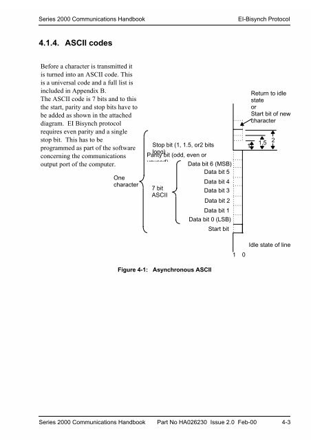
<strong>Series</strong> <strong>2000</strong> <strong>Communications</strong> <strong>Handbook</strong>EI-Bisynch Protocol4.1.4. ASCII codesBefore a character is transmitted itis turned into an ASCII code. Thisis a universal code and a full list isincluded in Appendix B.The ASCII code is 7 bits and to thisthe start, parity and stop bits have tobe added as shown in the attacheddiagram. EI Bisynch protocolrequires even parity and a singlestop bit. This has to beprogrammed as part of the softwareconcerning the communicationsoutput port of the computer.OnecharacterStop bit (1, 1.5, or2 bitslong)Parity bit (odd, even orunused) Data bit 6 (MSB)Data bit 57 bitASCIIData bit 4Data bit 3Data bit 2Data bit 1Data bit 0 (LSB)Start bit1 01Return to idlestateorStart bit of newcharacter1,5 2Idle state of lineFigure 4-1: Asynchronous ASCII<strong>Series</strong> <strong>2000</strong> <strong>Communications</strong> <strong>Handbook</strong> Part No HA026230 Issue 2.0 Feb-00 4-3