SECTION 9: STREET LIGHTING SYSTEM DESIGN - Woodland
SECTION 9: STREET LIGHTING SYSTEM DESIGN - Woodland
SECTION 9: STREET LIGHTING SYSTEM DESIGN - Woodland

You also want an ePaper? Increase the reach of your titles
YUMPU automatically turns print PDFs into web optimized ePapers that Google loves.
Engineering Design Standardsinsulation, solid or stranded copper, sized and color coded in accordance withthese standards and the National Electric Code. The same color of wire must beused for the whole length of the circuit. Tape shall not be used to identify thecolor of the wire.The minimum conductor shall be No. 4 A.W.G. on a direct underground service.The minimum conductor size from the service point to the service can, shall beNo. 4 A.W.G. The size of each conductor from the service point to the luminairesshall be such that the voltage drop along each circuit will not exceed five percent(5%) of the nominal service voltage to be used which is 120 volts. Calculationsshall be made substantiating the design criteria for every circuit. Calculationsshall also be made showing the total load in amperes of each circuit at the servicecan.The minimum size for street lighting conductors shall be No. 10 A.W.G. exceptthat No. 12 A.W.G. may be used from the luminaire to the adjacent pull box.A photo cell is required in each service system, it shall be connected to the servicecan with three No. 14 A.W.G.A. All traffic signal loop wire splices to the home run must be hot dipped insolder, then three (3) layers of electrical rubber tape applied. Two layersof PVC tape must be applied over the rubber tape. The whole splice mustthem be covered with scotch coat.B. All other splices in pull boxes must be wire nutted, then three layers ofPVC tape applied over the wire nut extending to a length of a minimum oftwo inches (2") over the wire. Then the whole splice must be dipped orcovered with scotch coat.C. Exceptions shall be made for street lighting splices in pull boxes. Ifconductors can not be spliced with wire nut because of the size of theconductors, then multi tap, plastic encased, weather rated lug shall beused. The commonly used name for these connectors is a Polarisconnector or an approved equal can be used. The same tape and scotchcoat procedure used for wire nut connections shall be performed whenusing this exception.9.15 PHOTO CELLA single twist-lock receptacle photo cell shall be provided on the luminairenearest to the service point for each service.9.16 CONDUITSConduits shall be sized in accordance with the National Electrical Code with aminimum size of 1½" in diameter. Larger size conduits may be required at theCity’s discretion.City of <strong>Woodland</strong> 1-117 Standard Specifications and Details 2007
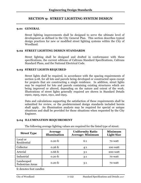
Engineering Design Standards9.17 RIGHT-OF-WAY AND EASEMENTSStreet lighting improvements shall be placed within public easement dedicationsor rights-of-way. The easements or rights-of-way should be sufficient in width toprovide access for operations and maintenance.9.18 ELECTRICAL EQUIPMENT AND WORKControl and switching equipment and fusing of all circuits shall meet therequirements of Caltrans Standard Specifications, Caltrans Standard Plans, andNational Electrical Code.9.19 MASTER PLANNINGMaster planning is the determination of street light locations between controlpoints. Control points are proposed street light locations at street intersections.The purpose for master planning is to end up with an overall uniform street lightsystem meeting minimum requirements. On collector and arterial streets, masterplanning shall apply to both sides of the street. The procedure for masterplanning is outlined as follows:A. Determine the nearest intersections each way from the street lightlocations required. Determine the location of the street lights at theintersections in conformance with these design standards.B. Determine the existence of any City owned and maintained street lightssituated between the adjacent intersections above.C. Determine the distance between the adjacent designed intersection streetlights above and/or adjacent existing street lights, whichever are nearest tothe street light locations being determined.D. Divide the distance into the most possible equal spaces between lights thatcan be obtained in conformance with the spacing requirements herein.E. Compare the light locations to intersecting property line, driveways,pedestrian lanes and utility obstructions as follows:1. If the locations fall close to a property line and the street lightlocation can be adjusted to the property line while staying withinthe maximum spacing allowed, then the adjustment should bemade.2. Generally, street lights should be situated at intersecting propertylines for residential lots with minimal frontage (75 feet or less). Thelight spacing may have to be unbalanced with additional lightsbeing added to attain this and still comply with the maximumspacing allowed.City of <strong>Woodland</strong> 1-118 Standard Specifications and Details 2007
Engineering Design Standards3. Street light locations shall be adjusted to miss driveways andexisting utility obstructions by five feet (5').City of <strong>Woodland</strong> 1-119 Standard Specifications and Details 2007
Engineering Design StandardsFIGURE 9bCity of <strong>Woodland</strong> 1-121 Standard Specifications and Details 2007
Engineering Design StandardsFIGURE 9cCity of <strong>Woodland</strong> 1-122 Standard Specifications and Details 2007
Engineering Design StandardsFIGURE 9dCity of <strong>Woodland</strong> 1-123 Standard Specifications and Details 2007