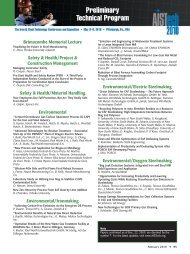
580 / <strong>Metallography</strong> <strong>and</strong> <strong>Microstructures</strong> <strong>of</strong> Ferrous Alloyswhile the secondary carbides are very distinct(see also Fig. 39, 40).The microstructure <strong>of</strong> an Fe-C-Cr cast iron afterheat treatment, revealed with glyceregia <strong>and</strong>Fig. 66 As-cast ductile iron (Fe-3.45%C-2.25%Si-0.30%Mn-0.04%P-0.01%S-0.8%Ni-0.07%Mg-0.55%Cu). Nodular graphite size is 20 lm. Aspolished.100examined with BFI <strong>and</strong> DFI, is shown in Fig. 49<strong>and</strong> 50, respectively. The details <strong>of</strong> the microstructurewere revealed much more strongly withDFI than with BFI.Fig. 68 As-cast ductile iron. Nodular graphite size is100 lm. As-polished. 100Polarized Light Response. Polarized light isobtained by placing a polarizer (usually a Polaroidfilter, Polaroid Corp.) in front <strong>of</strong> the condenserlens <strong>of</strong> the microscope <strong>and</strong> placing an analyzer(another Polaroid filter) before theeyepiece. The polarizer produces plane-polarizedlight that strikes the surface <strong>and</strong> is reflectedthrough the analyzer to the eyepieces. If an anisotropicmetal is examined with the analyzer set90 to the polarizer, the grain structure will bevisible. However, viewing <strong>of</strong> an isotropic metal(cubic metals) under such conditions will producedark, extinguished conditions (completedarkness is not possible using Polaroid filters).Polarized light is particularly useful in metallographyfor revealing grain structures <strong>and</strong> twinningin anisotropic metals <strong>and</strong> alloys as well as foridentifying anisotropic phases <strong>and</strong> inclusions.This method also improves the contrast <strong>of</strong> microstructures,providing more structural details(Ref. 4).Figure 51 shows the microstructure <strong>of</strong> agraphite nodule in BFI, while Fig. 52 shows thesame nodule in crossed polarized light. Polarizedlight reveals much better than BFI the radialstructure <strong>of</strong> the graphite nodule that grows fromthe central nucleus. Also, the cross, which ischaracteristic <strong>of</strong> the perfectly formed graphitenodule, can be made visible only with the use <strong>of</strong>this technique. Figure 53 shows the anisotropiclayered structure <strong>of</strong> graphite flakes, which alsorespond to polarized light. In both cases, the colors<strong>of</strong> graphite vary due to the anisotropy <strong>of</strong>graphite. Figure 54 shows the microstructure <strong>of</strong>ADI, consisting <strong>of</strong> martensite <strong>and</strong> a smallFig. 67 As-cast ductile iron (Fe-3.6%C-2.9%Si-0.14%Mn-0.04%P-0.02%S-0.16%Ni-0.06%Mg). Nodular graphite size is 40 lm. As-polished.100Fig. 69 As-cast ductile iron. Imperfectly formed graphitenodules. As-polished. 100Fig. 70 As-cast ductile iron. Exploded graphite. As-polished.100
NÚMERO ESPECIAL DEL XII SÍNODO GENERALLa Gruta del Getsemaní en el jardín de los Santos Juan y Pablomultirracial y multirreligioso. El último CapítuloGeneral trató pr<strong>of</strong>éticamente el tema de la globalización.El Documento Capitular afirma:“‘Solidaridad’ es la palabra escogida para describiruna nueva manera de estar juntos comopasionistas en misión por la vida del mundo. Las‘nuevas’ realidades requieren ‘nuevas’ respuestasen la fe. La solidaridad exige de cada uno unaconversión pr<strong>of</strong>unda de la mente y del corazón. Setrata de un crecimiento en la comprensión de quela vida es un don para compartir” (DC 4.6).Ha llegado ya el momento de crear “una nuevamanera de estar juntos”, de “dar respuestas nuevasa realidades nuevas” no sólo en el ámbito comunitarioo provincial, sino en toda la Congregación.Reestructurar para revitalizar, reestructurarpara permitir un mejor flujo de vida de una partede la Congregación hacia la otra “en un sólo cuerpoy un sólo espíritu”. Ha llegado el tiempo deabrirse al don de la vida para que todos en laCongregación tengamos la posibilidad de unanueva vida. Donándonos permanecemos; preservándonosy rechaz<strong>and</strong>o la posibilidad de abrirnosnos engañamos, al creer que permanecemos ysobrevivimos, cerr<strong>and</strong>o de esta manera el horizontede futuro: “quien quiera salvar la propiavida, la perderá; pero quien la pierda por mí ypor el evangelio, la salvará” (Mc 8, 35).Es tiempo de pensar más como Congregaciónque como Provincia, recuper<strong>and</strong>o la frescuraevangélica y la capacidad de diálogo entre todaslas partes de la Congregación, con intercambio dedones entre las diversas culturas y naciones.Donde hay una auténtica y sincera comunicación,allí se realiza la verdadera comunión. Es necesarioentrar en la “cultura del otro” para comprendersus ideas, compartir sus emociones, compartir sussueños. Uno de estos sueños consiste en que laCongregación se transforme de tal manera queparezca una sola provincia y en cuanto tal viva ysea enviada a todas las razas del mundo paraanunciar la Buena Noticia. Jesús nos quiere multiculturalesy multiétnicos: “Id y haced discípulosa todas las naciones” (Mt 28, 19).Pero, más allá de preguntarse el por qué deuna Reestructuración y de llegar a la convicciónde que ya es inevitable realizarla, es necesariopreguntarse y discernir cuál Reestructuración senecesita hoy para revitalizar la Congregación ypara ser, por tanto, eficaces en la Misión. ¿Quétipo de Congregación queremos para el mundode hoy con su secularización, su violencia y suterrorismo, su agresividad en el ámbito global yfamiliar, difundida incluso en las pequeñas cosascotidianas? Mucho nace del olvido de la Pasiónde Jesús y de los gr<strong>and</strong>es “valores” humanos ycristianos y de la incapacidad de amar y de reconciliarse.¿Qué Congregación fundaría hoy San Pablode la Cruz para los males de nuestro tiempo ypara la vitalidad misma de la Congregación? Y,por ende, nosotros, ¿qué tipo de Congregaciónpodemos establecer como hipótesis para nuestrosdías? ¿Y dentro de diez años? ¿Cuál vidndomly oriented graphite flakeswith a maximum length <strong>of</strong> 320 lm (type A flakegraphite in the ASTM A 247 classifications).Figure 59 shows a fine, type D flake graphitewith a maximum length <strong>of</strong> 40 lm, also in a hypoeutecticalloy, but it solidified at a higher coolingrate, which promoted the interdendritic distribution.Type A graphite in a hypereutecticgray iron is shown in Fig. 60. It has the mostdesired shape <strong>and</strong> distribution, <strong>and</strong> it is verycharacteristic <strong>of</strong> gray iron casts with high machinability.The maximum length <strong>of</strong> graphite flakesis 160 lm. Figures 61 <strong>and</strong> 62 show type E <strong>and</strong>type B graphite, respectively, which occur in hypereutecticgray iron at high cooling rates. Notein Fig. 62 that each rosette group <strong>of</strong> graphiterepresents one eutectic cell. That type <strong>of</strong> graphiteis characteristic <strong>of</strong> thin-walled castings.Fig. 72 As-cast iron with compacted graphite (Fe-3.7%C-2.3%Si-0.21%Mn-0.03%P-0.01%S-0.82%Ni-0.02%Mg). Graphite size is 80 to 160 lm. As polished.100Fig. 74 The diagram <strong>of</strong> correlation between a type <strong>of</strong> matrix in nonalloyed cast irons <strong>and</strong> silicon <strong>and</strong> phosphoruscontent as well as the thickness, R, <strong>of</strong> the casting wall, which relates to the cooling rate. K g C (Si logR)is a coefficient <strong>of</strong> graphitization, <strong>and</strong> C E C 1 ⁄3Si 1 ⁄3P is the coefficient <strong>of</strong> saturation (carbon equivalent). Region Iis white cast iron (pearlite, cementite, no graphite); Region IIa is mottled cast iron (pearlite, graphite, cementite); RegionIIb is ferritic-pearlitic cast iron; Region III is ferritic cast iron. Source: Ref 13