Metallography and Microstructures of Cast Iron
Metallography and Microstructures of Cast Iron
Metallography and Microstructures of Cast Iron

Create successful ePaper yourself
Turn your PDF publications into a flip-book with our unique Google optimized e-Paper software.
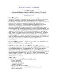
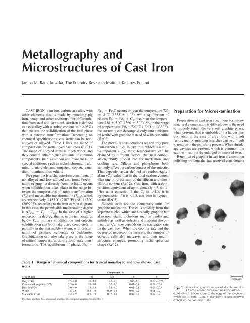
<strong>Metallography</strong> <strong>and</strong><strong>Microstructures</strong> <strong>of</strong> <strong>Cast</strong> <strong>Iron</strong>Janina M. Radzikowska, The Foundry Research Institute, Kraków, Pol<strong>and</strong>CAST IRON is an iron-carbon cast alloy withother elements that is made by remelting pigiron, scrap, <strong>and</strong> other additions. For differentiationfrom steel <strong>and</strong> cast steel, cast iron is definedas a cast alloy with a carbon content (min 2.03%)that ensures the solidification <strong>of</strong> the final phasewith a eutectic transformation. Depending onchemical specifications, cast irons can be nonalloyedor alloyed. Table 1 lists the range <strong>of</strong>compositions for nonalloyed cast irons (Ref 1).The range <strong>of</strong> alloyed irons is much wider, <strong>and</strong>they contain either higher amounts <strong>of</strong> commoncomponents, such as silicon <strong>and</strong> manganese, orspecial additions, such as nickel, chromium, aluminum,molybdenum, tungsten, copper, vanadium,titanium, plus others.Free graphite is a characteristic constituent <strong>of</strong>nonalloyed <strong>and</strong> low-alloyed cast irons. Precipitation<strong>of</strong> graphite directly from the liquid occurswhen solidification takes place in the range betweenthe temperatures <strong>of</strong> stable transformation(T st ) <strong>and</strong> metastable transformation (T mst ), whichare, respectively, 1153 C (2107 F) <strong>and</strong> 1147 C(2097 F), according to the iron-carbon diagram.In this case, the permissible undercooling degreeis DT max T st T mst . In the case <strong>of</strong> a higherundercooling degree, that is, in the temperaturesbelow T mst , primary solidification <strong>and</strong> eutecticsolidification can both take place completely orpartially in the metastable system, with precipitation<strong>of</strong> primary cementite or ledeburite.Graphitization can also take place in the range<strong>of</strong> critical temperatures during solid-state transformations.The equilibrium <strong>of</strong> phases Fe c Fe Fe 3 C occurs only at the temperature 723 2 C (1333 4 F), while equilibrium <strong>of</strong>phases Fe c Fe C gr occurs at the temperature738 3 C (1360 5 F). So, in the range<strong>of</strong> temperatures 738 to 723 C (1360 to 1333 F),the austenite can decompose only into a mixture<strong>of</strong> ferrite with graphite instead <strong>of</strong> with cementite(Ref 2).The previous considerations regard only pureiron-carbon alloys. In cast iron, which is a multicomponentalloy, these temperatures can bechanged by different factors: chemical composition,ability <strong>of</strong> cast iron for nucleation, <strong>and</strong>cooling rate. Silicon <strong>and</strong> phosphorus bothstrongly affect the carbon content <strong>of</strong> the eutectic.That dependence was defined as a carbon equivalent(C e ) value that is the total carbon contentplus one-third the sum <strong>of</strong> the silicon <strong>and</strong> phosphoruscontent (Ref 2). <strong>Cast</strong> iron, with a compositionequivalent <strong>of</strong> approximately 4.3, solidifiesas a eutectic. If the C e is 4.3, it ishypereutectic; if it is 4.3, cast iron is hypoeutectic(Ref 3).Eutectic cells are the elementary units forgraphite nucleation. The cells solidify from theseparate nuclei, which are basically graphite butalso nonmetallic inclusions such as oxides <strong>and</strong>sulfides as well as defects <strong>and</strong> material discontinuities.Cell size depends on the nucleation ratein the cast iron. When the cooling rate <strong>and</strong> thedegree <strong>of</strong> undercooling increase, the number <strong>of</strong>eutectic cells also increases, <strong>and</strong> their microstructurechanges, promoting radial-sphericalshape (Ref 2).Preparation for MicroexaminationPreparation <strong>of</strong> cast iron specimens for microstructuralexamination is difficult due to the needto properly retain the very s<strong>of</strong>t graphite phase,when present, that is embedded in a harder matrix.Also, in the case <strong>of</strong> gray irons with a s<strong>of</strong>tferritic matrix, grinding scratches can be difficultto remove in the polishing process. When shrinkagecavities are present, which is common, thecavities must not be enlarged or smeared over.Retention <strong>of</strong> graphite in cast iron is a commonpolishing problem that has received considerableTable 1ironsType <strong>of</strong> ironRange <strong>of</strong> chemical compositions for typical nonalloyed <strong>and</strong> low-alloyed castComposition, %C Si Mn P SGray (FG) 2.5–4.0 1.0–3.0 0.2–1.0 0.002–1.0 0.02–0.025Compacted graphite (CG) 2.5–4.0 1.0–3.0 0.2–1.0 0.01–0.1 0.01–0.03Ductile (SG) 3.0–4.0 1.8–2.8 0.1–1.0 0.01–0.1 0.01–0.03White 1.8–3.6 0.5–1.9 0.25–0.8 0.06–0.2 0.06–0.2Malleable (TG) 2.2–2.9 0.9–1.9 0.15–1.2 0.02–0.2 0.02–0.2FG, flake graphite; SG, spheroidal graphite; TG, tempered graphite. Source: Ref 1Fig. 1 Spheroidal graphite in as-cast ductile iron (Fe-3.7%C-2.4%Si-0.59%Mn-0.025%P-0.01%S-0.095%Mo-1.4%Cu) close to the edge <strong>of</strong> the specimen,which was 30 mm (1.2 in.) in diameter. The specimen wasembedded. As-polished. 100
<strong>Metallography</strong> <strong>and</strong> <strong>Microstructures</strong> <strong>of</strong> <strong>Cast</strong> <strong>Iron</strong> / 567can be reduced to the desired size for metallographicspecimens by using a laboratory abrasivecut<strong>of</strong>f saw or a b<strong>and</strong> saw. If the casting wasFig. 7 Same as in Fig. 6 but after final polishing withthe 1 lm diamond paste applied on a naplesscloth. Graphite is free <strong>of</strong> any visible pullouts. As-polished.400sectioned by flame cutting, the specimen mustbe removed well away from the heat-affectedzone. The pieces cut out for metallographic examinationmay be ground prior to mounting (thismay be done to round <strong>of</strong>f sharp cut edges or toreduce the roughness <strong>of</strong> b<strong>and</strong>-saw-cut surfaces)<strong>and</strong> subsequent preparation. Overheating isavoided by proper selection <strong>of</strong> the speed <strong>of</strong> cut<strong>of</strong>fsaws, the use <strong>of</strong> the correct wheel, <strong>and</strong> adequatewater cooling. Overheating during grindingis avoided by using fresh abrasive paper <strong>and</strong>proper cooling. When metallographic specimensare cut out from the st<strong>and</strong>ard cast bars, they aresometimes prepared using st<strong>and</strong>ard machineshop equipment, such as turning in a lathe ormilling. These devices can deform the testpiecesurfaces to a considerable depth, so care must beexercised to remove any damage from theseoperations before starting specimen preparation.Mounting. Specimens can be mounted in apolymeric material using either cold or hotmounting procedures. The mounting resin ischosen depending on the cast iron hardness (s<strong>of</strong>tor hard) <strong>and</strong> the need to enhance edge retention.Use <strong>of</strong> an incorrect resin, or ignoring the mountingprocess, can make it very difficult to obtainproperly polished graphite in the area close tothe specimen edge. Figures 1 <strong>and</strong> 2 show themicrostructure <strong>of</strong> spheroidal graphite in ductileiron close to the edge <strong>of</strong> the specimens, whichwere cut <strong>of</strong>f from a 30 mm (1.2 in.) diameter bar<strong>and</strong> polished with <strong>and</strong> without embedding in apolymer resin, respectively. In the specimen preparedwithout embedding in a resin, the graphitewas pulled out, while in the specimen that wasembedded in a resin <strong>and</strong> prepared, the graphitenodules were perfectly retained. Figures 3 <strong>and</strong> 4show that the uniform grinding <strong>of</strong> nonmountedspecimens is more difficult, <strong>and</strong> the flake graphitein gray iron close to the edge <strong>of</strong> such a specimenis not polished perfectly, in comparison towell-polished graphite in the mounted specimen.Grinding <strong>and</strong> Polishing. To ensure propergraphite retention, the use <strong>of</strong> an automatedgrinding-polishing machine is recommendedover manual preparation. The automated equipmentmakes it possible, in comparison to manualspecimen preparation, to properly control theorientation <strong>of</strong> the specimen surface relative tothe grinding or polishing surface, to maintainconstantly the desired load on the specimens, touniformly rotate the specimens relative to thework surface, <strong>and</strong> to control the time for eachpreparation step. Proper control <strong>of</strong> these factorsinfluences graphite retention, although other factorsare also important.A good, general principle is to minimize thenumber <strong>of</strong> grinding <strong>and</strong> polishing stages. Also,the load on each specimen, or on all specimensin the holder, must be chosen to obtain a correctlypolished surface in the shortest possibletime. This precludes the risk <strong>of</strong> pulling out thegraphite phase <strong>and</strong> ensures that the graphite precipitateswill be perfectly flat with sharp boundaries.The recommended procedure for automatedpreparation <strong>of</strong> the specimens <strong>of</strong> nonalloyed <strong>and</strong>low-alloyed cast iron with graphite specimens isto grind with a high-quality, waterpro<strong>of</strong> 220- or240-grit (or equivalent) SiC paper until plane,with a load <strong>of</strong> 100 N for six specimens mountedin the sample holder, with central loading. Pol-Fig. 8 Same as in Fig. 7 but after final polishing withthe 1 lm diamond suspension applied on anapped cloth. The arrows show the pulled-out graphite.Aspolished.400Fig. 9 White high-chromium iron (Fe-3.2%C-4.65%Cr-2.9%Mn-0.51%Si-0.050%P-0.024%S). Eutectic<strong>and</strong> secondary carbides in the matrix. Specimen was preparedcorrectly. The casting was austenitized at 1000 C(1830 F), held 1 h, furnace cooled to 400 C (750 F) for2 h, taken to salt bath at 400 C (750 F), held for 4 h, <strong>and</strong>air cooled. Etched with glyceregia. 500Fig. 10 White high-chromium iron (Fe-3.16%C-8.86%Cr-0.50%Si-3.04%Mn-0.051%P-0.018%S). Eutectic <strong>and</strong> secondary carbides in the matrix.Specimen was prepared incorrectly. The casting was austenitizedat 1000 C (1830 F), held 1 h, furnace cooled to700 C (1290 F) for 2 h, taken to salt bath at 700 C (1290F), held 4 h, <strong>and</strong> air cooled. Etched with glyceregia. 500
<strong>Metallography</strong> <strong>and</strong> <strong>Microstructures</strong> <strong>of</strong> <strong>Cast</strong> <strong>Iron</strong> / 569● First step: P220 grit until plane.● Second step: P500 grit for 3 min.● Third step: P1000 grit for 3 minPolishing is done in three steps, with differentgrain size diamond in paste for the first two steps:Fig. 11 Ductile iron (Fe-3.8%C-2.4%Si-0.28%Mn-1.0%Ni-0.05%Mg) after annealing. Ferrite <strong>and</strong>approximately 5% pearlite. Etched with 2% nital. 100.Courtesy <strong>of</strong> G.F. V<strong>and</strong>er Voort, Buehler Ltd.● First step: 3 lm diamond, 120 N load/sixspecimens for 3 min with a napless cloth.● Second step: 1lm diamond, 100 N load/sixspecimens for 3 min with a napless clothThe last polishing step is carried out with a colloidalsilica suspension on a napless syntheticFig. 13 Same as in Fig. 12 but after etching with 4%picral. Pearlite was etched uniformly. 500polyurethane pad but in a single specimenholder with an individual load <strong>of</strong> 30 N for 1.5min.Figure 9 shows the microstructure <strong>of</strong> a heattreated chromium iron after this preparation. Thecarbides are perfectly flat, with very sharp edges<strong>and</strong> boundaries etched uniformly. Figure 10shows the primary eutectic carbides in the microstructure<strong>of</strong> a high-chromium iron. They appearto be sticking out from the matrix, <strong>and</strong> theirboundaries are not outlined uniformly. This resultoccurs if the load is too low or the final polishingtime on the silica suspension is too long.Both problems will result in too much removal<strong>of</strong> the s<strong>of</strong>ter matrix that was surrounding the primarycarbides.During grinding, the paper must be moistenedwith flowing tap water, <strong>and</strong> the specimens shouldbe washed with water after each step. Also, duringthe first planning step, the sheet <strong>of</strong> papershould be changed every 1 min. Used grit paperis not effective <strong>and</strong> will introduce heat <strong>and</strong> damage,impairing specimen flatness. During polishingwith diamond paste from a tube, the cloth ismoistened with the recommended lubricant forthe paste. If a water-based diamond suspensionis applied on the cloth, the use <strong>of</strong> an additionallubricant is not required.The speed <strong>of</strong> the grinding-polishing head was150 rpm, <strong>and</strong> it was constant. The speed <strong>of</strong> theplaten during grinding was always 300 rpm, <strong>and</strong>during polishing was always 150 rpm. After eachgrinding step, the specimens were washed withrunning tap water <strong>and</strong> dried with compressed air,while after each polishing step, they werewashed with alcohol <strong>and</strong> dried with hot air froma hair dryer.Fig. 12 As-cast gray iron (Fe-2.8%C-0.8%Si-0.4%Mn-0.1%S-0.35%P-0.3%Cr). Pearlite. Etched with4% nital. Arrows show the white areas with weakly etchedor nonetched pearlite. 500Fig. 14 As-cast high-chromium white iron (Fe-1.57%C-18.64%Cr-2.86%Mn-0.53%Si-0.036%P-0.013%S). Eutectic chromium carbides typeM 7C 3 in austenitic matrix. Etched with glyceregia. 500Fig. 15 Same as in Fig. 14 but after etching with 4%nital. 500
570 / <strong>Metallography</strong> <strong>and</strong> <strong>Microstructures</strong> <strong>of</strong> Ferrous AlloysMicroexamination MethodsFig. 16 As-cast ductile iron (Fe-3.07%C-0.06%Mn-2.89%Si-0.006%P-0.015%S-0.029%Mg). C,cementite; L, ledeburite; F, ferrite; <strong>and</strong> P, pearlite. Etchedwith 4% nital. 650 (microscopic magnification 500)Chemical Etching. The examination <strong>of</strong> theiron microstructure with a light optical microscopeis always the first step for phase identification<strong>and</strong> morphology. One should always beginmicrostructural investigations by examiningthe as-polished specimen before etching. This isa necessity, <strong>of</strong> course, for cast iron specimens, ifone is to properly examine the graphite phase.Fig. 18 As-cast gray iron (Fe-3.24%C-2.32%Si-0.54%Mn-0.71%P-0.1%S). E, phosphorousternary eutectic. Etched with 4% nital. 100St<strong>and</strong>ard Etchants. To see the microstructuraldetails, specimens must be etched. Etchingmethods based on chemical corrosive processeshave been used by metallographers for manyyears to reveal structures for black-<strong>and</strong>-whiteimaging.Specimens <strong>of</strong> nonalloyed <strong>and</strong> low-alloyedirons containing ferrite, pearlite, the phosphoruseutectic (steadite), cementite, martensite, <strong>and</strong>bainite can be etched successfully with nital atroom temperature to reveal all <strong>of</strong> these microstructuralconstituents. Usually, this is a2to4%alcohol solution <strong>of</strong> nitric acid (HNO 3 ) (Table 2,etch No. 1). Figure 11 shows a nearly ferriticannealed ductile iron with uniformly etchedgrain boundaries <strong>of</strong> ferrite <strong>and</strong> a small amount<strong>of</strong> pearlite. Nital is very sensitive to the crystallographicorientation <strong>of</strong> pearlite grains, so, in thecase <strong>of</strong> a fully pearlitic structure, it is recommendedto use picral, which is an alcohol solution<strong>of</strong> 4% picric acid (Table 2, etch No. 2). Figures12 <strong>and</strong> 13 show the differences in revealingthe microstructure <strong>of</strong> pearlite with nital or picral.Picral does not etch the ferrite grain boundaries,or as-quenched martensite, but it etches the pearliticstructure more uniformly, while nital leaveswhite, unetched areas, especially in the casewhere pearlite is very fine.When the austempering heat treatment is veryshort, the microstructure <strong>of</strong> austempered ductileiron (ADI) consists <strong>of</strong> martensite <strong>and</strong> a smallamount <strong>of</strong> acicular ferrite. After etching in 4%nital, martensite as well as acicular ferrite areboth etched intensively, which makes it very dif-Fig. 17 Same as in Fig. 16 but after etching with hotalkaline sodium picrate. C, eutectic cementite;L, ledeburite; F, ferrite; <strong>and</strong> P, pearlite with slightly etchedcementite. 650 (microscopic magnification 500)Fig. 19 Same as in Fig. 18 but after etching with KlemmI reagent. E, phosphorous ternary eutectic.100Fig. 20 Austempered ductile iron (Fe-3.6%C-2.5%Si-0.06%P-1.5%Ni-0.7%Cu). CB, cell boundaries;H, ferritic halo around the graphite nodules. Etchedwith Klemm I reagent. 200
<strong>Metallography</strong> <strong>and</strong> <strong>Microstructures</strong> <strong>of</strong> <strong>Cast</strong> <strong>Iron</strong> / 571ficult to distinctly see the needles <strong>of</strong> acicular ferrite.Picral reveals this phase very well; martensiteis barely etched due to the very shortaustempering heat treatment <strong>of</strong> the specimen,Fig. 21 Same as in Fig. 20 but after etching with Beraha’sCdS reagent. H, ferritic halo; CB, cellboundaries. 250which was 2 min, because the martensite was asquenched.The needles <strong>of</strong> acicular ferrite aredark <strong>and</strong> very sharp (Fig. 32, 33). In this case,picral is very convenient for estimating theamount <strong>and</strong> morphology <strong>of</strong> the acicular ferrite inthe ADI microstructure. Picral is safer to beFig. 23 As-cast gray iron (Fe-3.33%C-1.64%Si-0.31%Mn-1.37%P-0.107%S). Ternary phosphoruseutectic. Etched with 4% nital. 1300 (microscopicmagnification 1000)stored in the lab than nital, which can be an explosivemixture under certain conditions when itis stored in a tightly closed bottle.Glyceregia (Table 2, etch No. 3), which is amixture <strong>of</strong> glycerine, hydrochloric acid (HCl),<strong>and</strong> nitric acid (HNO 3 ), is recommended for revealingthe microstructure <strong>of</strong> high-chromium<strong>and</strong> chromium-nickel-molybdenum irons. Figure14 shows the microstructure <strong>of</strong> a high-chromiumcast iron after etching with glyceregia (seealso Fig. 43, 49, <strong>and</strong> 96). Nital can be also usedfor revealing the carbide morphology in the microstructure<strong>of</strong> chromium or chromium-nickelirons when the carbon <strong>and</strong> chromium contentpromotes solidification <strong>of</strong> eutectic carbides.When the microstructure <strong>of</strong> a high-chromiumwhite iron contains columnar primary carbides,glyceregia is recommended.Figure 15 shows the microstructure <strong>of</strong> thesame cast iron as Fig. 14 but after etching with4% nital (see also Fig. 40, 41). Both etchantsreveal carbide boundaries sharply <strong>and</strong> uniformly.Selective Color Etching. If the black-<strong>and</strong>whiteetchants are inadequate for positive identification<strong>of</strong> the iron microstructures, other proceduresmust be used, such as selective coloretching. The reagents referred to as tint etchantsare usually acidic solutions with either water oralcohol as a solvent. They are chemically balancedto deposit a thin (40 to 500 nm), transparentfilm <strong>of</strong> oxide, sulfide, complex molybdate,elemental selenium, or chromate on thespecimen surface. Coloration is developed by interferencebetween light rays reflected at the in-Fig. 22 Nodular iron (Fe-3.9%C-2.9%Si-0.32%Mn-0.06%P-0.037%Mg-1.5%Ni-0.57%Cu). Siliconmicrosegregation was revealed. The casting was annealed.Etched with hot aqueous solution <strong>of</strong> sodiumhydroxide, picric acid, <strong>and</strong> potassium pyrosulfite (Table 2,etchant No. 7). 500Fig. 24 Same as in Fig. 23 but after etching with hotalkaline sodium picrate. C, cementite; F, ferrite(unaffected); IP, iron phosphide ferrite; <strong>and</strong> TiN, titaniumnitride. 1300 (microscopic magnification 1000)Fig. 25 Same as in Fig. 23 but after etching with KlemmI reagent. F, ferrite; C, cementite; <strong>and</strong> C IP,cementite iron phosphide inside the precipitate <strong>of</strong> phosphorouseutectic. 1300 (microscopic magnification1000)
572 / <strong>Metallography</strong> <strong>and</strong> <strong>Microstructures</strong> <strong>of</strong> Ferrous Alloysner <strong>and</strong> outer film surfaces. Crystallographic orientation,local chemical composition, <strong>and</strong>etching time affect film thickness <strong>and</strong> controlcolor production. The use <strong>of</strong> selective etchantsFig. 26 Same as in Fig. 23 but after etching with hotMurakami’s reagent. IP, iron phosphide; C F,cementite ferrite inside the precipitate <strong>of</strong> phosphorouseutectic. 1300 (microscopic magnification 1000)Fig. 28 Same as in Fig. 25 but after etching with Beraha’sreagent with selenic acid. IP, iron phosphide;C, cementite; <strong>and</strong> F, ferrite. The dark points in pearlite,which look like artifacts, can be iron phosphideprecipitates or fine, nonmetallic inclusions. 1300 (microscopicmagnification 1000)is invaluable for quantitative metallography, afield <strong>of</strong> growing importance (Ref 5).When ferritic-pearlitic microstructures <strong>of</strong> castiron contain large amounts <strong>of</strong> cementite <strong>and</strong> ledeburite,the differentiation <strong>of</strong> the white structuralconstituents is difficult after etching a specimenwith nital. In such cases, hot alkaline sodium picrate(ASP) is recommended (Table 2, etch No.4), which reveals cementite, tinted a browncolor, while ferrite remains unaffected. This etchis a mixture <strong>of</strong> sodium hydroxide (NaOH), picricacid, <strong>and</strong> distilled water. Figure 16 shows themicrostructure <strong>of</strong> a thin-walled, chilled ductileiron casting after etching with nital, while Fig.17 shows the microstructure <strong>of</strong> the same specimenafter etching with ASP; the brown-coloredcementite <strong>and</strong> ledeburite are clearly visible in thepearlitic-ferritic matrix (the cementite in pearlitewas also slightly tinted). It allows one to estimatethe amount <strong>of</strong> cementite that should be removedfrom the casting microstructure in the annealingprocess.Segregation <strong>of</strong> silicon <strong>and</strong> phosphorus in ironis very strong <strong>and</strong> can be revealed with selectivecolor etching methods. Klemm’s I reagent (Table2, etch No. 5), which tints ferrite while austenite<strong>and</strong> carbides remain colorless, consists <strong>of</strong>potassium metabisulfite (K 2 S 2 O 5 ) <strong>and</strong> a cold-saturatedwater solution <strong>of</strong> sodium thiosulfate(Na 2 S 2 O 3 •5H 2 O) <strong>and</strong> is one <strong>of</strong> the etchants thatcan be used to reveal phosphorus <strong>and</strong> silicon segregation.Usually, the distribution <strong>of</strong> the phosphorus eutectic,which solidifies in gray iron on the cellboundaries, is revealed by etching up to 4 minin 4% nital. Figure 18 shows the microstructure<strong>of</strong> as-cast gray iron with the ternary phosphorouseutectic. The cell boundaries, filled with steadite,Fig. 27 Same as in Fig. 26 but after overetching withhot Murakami’s reagent. IP, iron phosphide; C,cementite; <strong>and</strong> F, ferrite. 1300 (microscopic magnification1000)Fig. 29 As-cast gray iron (Fe-3.62%C-2.03%Si-1.13%P-0.61%Mn-0.137%S-0.113%Cr-0.478%Ni-0.004%Al). E, binary phosphorous eutectic; F,ferrite at the graphite precipitate; <strong>and</strong> P, pearlite. Etchedwith 4% nital. 500Fig. 30 Same as in Fig. 29 but after etching with hotalkaline sodium picrate <strong>and</strong> 4% nital. Pearliticmatrix is revealed; phosphorous eutectic is unaffected.500
<strong>Metallography</strong> <strong>and</strong> <strong>Microstructures</strong> <strong>of</strong> <strong>Cast</strong> <strong>Iron</strong> / 573are white, while their interiors are almost blackdue to overetching the pearlitic-ferritic matrix.Figure 19 shows the same microstructure afteretching with Klemm’s I reagent. The microregionsinside the eutectic cells with a lower phosphoruscontent are tinted a blue color, while theFig. 31 Same as in Fig. 29 but after etching with hotMurakami reagent. Only brown-tinted ironphosphide was revealed. 500areas with the ternary eutectic, situated at theboundaries <strong>of</strong> the eutectic cells, are almost colorless.In both cases, the cementite <strong>and</strong> ironFig. 33 Same as in Fig. 32 but after etching with 4%picral. AF, acicular ferrite; PM, plate martensite.1000phosphide in steadite are not etched, <strong>and</strong> the networkis clearly visible.Figure 20 shows silicon segregation in an ADImicrostructure after etching with Klemm’s I reagent.The regions outlining the cell boundaries,low in silicon, are tinted a blue color, while thevery thin halos around the graphite nodules,where the silicon content is highest, remain colorless.Acicular ferrite is orange, <strong>and</strong> austenite isnot tinted. Figure 21 shows the same microstructureafter etching with Beraha’s CdS reagent (Table2, etch No. 6), an aqueous solution <strong>of</strong> sodiumthiosulfate (Na 2 S 2 O 3 •5H 2 O), citric acid(C 6 H 8 O 7 •H 2 O), <strong>and</strong> cadmium chloride(CdCl 2 •2.5H 2 O). The silicon segregation is revealedthe same way as after using Klemm’s Ireagent.To reveal silicon segregation in nonalloyedductile cast iron inside eutectic cells, the hotaqueous solution <strong>of</strong> sodium hydroxide, picricacid, <strong>and</strong> potassium pyrosulfite (K 2 S 2 O 5 ) can beused (Table 2, etch No. 7). Figure 22 shows thedifferent colors <strong>of</strong> the microstructure, whichchange from green through red, yellow, blue, <strong>and</strong>dark brown to light brown as the silicon contentis changing from the graphite nodule to the cellboundaries. The regions with the lowest siliconcontent at the cell boundaries remain colorless.Before etching, ferritization <strong>of</strong> the specimen wascarried out to enhance the visibility <strong>of</strong> the microstructuralcolors.The revealing <strong>and</strong> differentiation <strong>of</strong> all constituentsin steadite is invaluable for the determination<strong>of</strong> the type <strong>of</strong> eutectic as well as theFig. 32 Austempered ductile iron (Fe-3.6%C-2.5%Si-0.056%P-0.052%Mg-0.7%Cu). Martensite<strong>and</strong> acicular ferrite. The casting was austempered at 900C (1650 F), held 2 h, taken to salt bath at 360 C (680 F),held 2 min, <strong>and</strong> air cooled. Etched with 4% nital. 1000Fig. 34 Same as in Fig. 32 but after etching with Beraha-Martensitereagent. PM, blue-yellow platemartensite; FM, brown fine martensite; <strong>and</strong> AF A, darkneedles <strong>of</strong> acicular ferrite surrounded with colorless austenite.1000Fig. 35 Same as in Fig. 32 but after etching with 10%sodium metabisulfite. PM, plate martensite;FM, fine martensite; <strong>and</strong> AF A, acicular ferrite <strong>and</strong> austenite.1000
574 / <strong>Metallography</strong> <strong>and</strong> <strong>Microstructures</strong> <strong>of</strong> Ferrous AlloysFig. 36 Austempered ductile iron (Fe-3.6%C-2.5%Si-0.052%Mg-0.7%Cu). AF, acicular ferrite; A,austenite; <strong>and</strong> M, martensite. The casting was austemperedat 900 C (1650 F), held 2 h, taken to salt bath at 360 C(680 F), held 30 min, <strong>and</strong> air cooled. Etched with 4% nital.1000Fig. 38 Same as in Fig. 36 but after etching with 10%sodium metabisulfite. AF, acicular ferrite; A,austenite; <strong>and</strong> M, martensite. 1000amount <strong>of</strong> each constituent. In the case <strong>of</strong> theternary phosphorous eutectic, which consists <strong>of</strong>ferrite, cementite, <strong>and</strong> iron phosphide (Fe 3 P), nitaldoes not help in the identification <strong>of</strong> the constituents,nor does it provide enough informationabout distribution <strong>of</strong> the eutectic constituents.Figure 23 shows the microstructure <strong>of</strong> the ternaryphosphorous eutectic in gray iron after etchingin 4% nital. The white areas that surroundthe ternary eutectic <strong>and</strong> are also visible insidethe eutectic can be either ferrite or cementite.Figure 24 shows the microstructure <strong>of</strong> the samespecimen after selective color etching with hotASP (Table 2, etchant No. 4). Cementite in theeutectic is tinted brown <strong>and</strong> blue colors (also inpearlite), while ferrite <strong>and</strong> iron phosphide are nottinted. To reveal the ferrite, the same specimenwas etched with Klemm’s I reagent. Figure 25shows the eutectic regions with precipitates <strong>of</strong>brown ferrite (also in pearlite), while cementite<strong>and</strong> iron phosphide are not tinted.Murakami’s reagent (Table 2, etch No. 8),used at 50 C (120 F) for 3 min <strong>and</strong> containingpotassium hydroxide (KOH), potassium ferricyanide(K 3 Fe(CN) 6 ), <strong>and</strong> distilled water, can beused for revealing <strong>and</strong> estimating the amount <strong>of</strong>iron phosphide in steadite. Figure 26 shows thisconstituent <strong>of</strong> the ternary phosphorous eutecticmicrostructure, which was tinted a light-browncolor, while cementite <strong>and</strong> ferrite remained colorless.The microstructure <strong>of</strong> the same specimenafter overetching (5 min) with the same reagentis shown in Fig. 27. This time, cementite wasalso revealed <strong>and</strong> was tinted a yellow color,while ferrite remained white. The color <strong>of</strong> theiron phosphide changed to a dark-brown <strong>and</strong>gray-blue color. Nevertheless, extending theetching time beyond 3 min is not recommended,because this can falsify the true results <strong>of</strong> themicrostructural examination.Good differentiation <strong>of</strong> all constituents in theternary phosphorus eutectic can be obtained withBeraha’s reagent (Table 2, etch No. 9), a mixture<strong>of</strong> hydrochloric acid (HCl), selenic acidFig. 37 Same as in Fig. 36 but after etching with Beraha-Martensitereagent. AF, acicular ferrite; A,austenite; <strong>and</strong> M, martensite. 1000Fig. 39 White alloyed cast iron (Fe-3.4%C-0.92%Mn-1.89%Si-9.52%Cr-6.27%Ni). Etched with Beraha-Martensite.PM, plate martensite; FM, fine martensite;EC, eutectic carbides type M 7C 3; SC, secondary carbides;<strong>and</strong> MS, manganese sulfite. The casting was heat treated:austenitized at 750 C (1380 F), held 2 h, <strong>and</strong> air cooled;tempered at 250 C (480 F), held 4 h, <strong>and</strong> air cooled.1300 (microscopic magnification 1000)Fig. 40 Same white iron as in Fig. 39 but after etchingwith 4% nital. M, martensite; EC, eutectic carbides;<strong>and</strong> SC, secondary carbides. 1300 (microscopicmagnification 1000)
<strong>Metallography</strong> <strong>and</strong> <strong>Microstructures</strong> <strong>of</strong> <strong>Cast</strong> <strong>Iron</strong> / 575Fig. 41 Same white iron as in Fig. 39 <strong>and</strong> 40 but ascast.Eutectic carbides in austenitic matrix.Etched with glyceregia. 500(H 2 SeO 4 ), <strong>and</strong> ethanol. According to Beraha,this etchant tints iron phosphide a dark-bluecolor, cementite a violet or dark red, <strong>and</strong> ferriteremains white. Figure 28 shows the microstructure<strong>of</strong> the ternary eutectic, with cementite tinteda light-pink color, while the rest <strong>of</strong> the constituentswere colored properly.Fig. 43 As-cast high-chromium white iron (Fe-4.52%C-0.4%Si-2.86%Mn-35.0%Cr-0.06%P-0.012%S). PC, primary carbides; EC, eutectic carbides,both M 7C 3 type. Etched with glyceregia. 500Figure 29 shows the microstructure <strong>of</strong> thepseudobinary phosphorous eutectic, which consists<strong>of</strong> iron phosphide <strong>and</strong> ferrite, after etchingwith 4% nital. The same specimen was etchedwith hot ASP (Table 2, etchant No. 4). This didnot tint the iron phosphide or the ferrite. Becausecementite is not present in the eutectic, the onlyetching was <strong>of</strong> cementite in the pearlite, whichshowed up very lightly. To reveal the microstructure<strong>of</strong> the eutectic, the specimen was nextetched with 4% nital. Figure 30 shows the resultsafter using hot ASP <strong>and</strong> then nital. Hot Murakami’sreagent perfectly tinted the iron phosphidein the binary phosphorous eutectic a browncolor, while pearlite was colorless, as shown inFig. 31.Beraha-Martensite (B-M) (Table 2, etch No.10) <strong>and</strong> aqueous 10% sodium metabisulfite(SMB) (Table 2, etch No. 11) reagents for selectivecolor etching are very useful in cases wheremicrostructural details are very fine <strong>and</strong> barelyvisible after etching with nital. They reveal all<strong>of</strong> the constituents, tinting them to expected colorsthat are useful for verifying that the heattreatment process was carried out correctly.The B-M etchant is a mixture <strong>of</strong> stock solution(1:5, HCl to water), potassium metabisulfite(K 2 S 2 O 5 ), <strong>and</strong> ammonium acid fluoride(NH 4 F•HF). According to Ref 6, B-M tints martensitea blue color <strong>and</strong> bainite a brown color,while the residual austenite <strong>and</strong> carbides remainunaffected.The B-M etchant can be used for identification<strong>of</strong> the constituents after heat treatment <strong>of</strong> castiron by tinting phases to different colors. It alsoFig. 42 Same as in Fig. 41 but after etching with Lichtenegger<strong>and</strong> Bloech I. Austenite is dark brown,<strong>and</strong> dendritic segregation is visible around unaffected carbides.1000Fig. 44 Same as in Fig. 43 but after etching with Murakami’sreagent (at room temperature). PC, orangeprimary carbides; EC, orange <strong>and</strong> gray eutectic carbides.400Fig. 45 Same as in Fig. 43 but as-polished <strong>and</strong> examinedin differential interference contrast. Primary<strong>and</strong> eutectic carbides are sticking up from the s<strong>of</strong>teraustenitic matrix. 400
576 / <strong>Metallography</strong> <strong>and</strong> <strong>Microstructures</strong> <strong>of</strong> Ferrous AlloysFig. 46 Same white iron as in Fig. 39 but after slightetching with 4% nital <strong>and</strong> examined in brightfieldillumination. EC, eutectic carbides type M 7C 3;SC,secondary carbides; <strong>and</strong> M, martensite. 1000improves microstructural contrast, enhancingvisibility <strong>and</strong> permitting estimation <strong>of</strong> evensmall amounts <strong>of</strong> the residual austenite (althoughx-ray diffraction results are always more than10% greater than by light microscopy) <strong>and</strong> finecarbides. Figure 32 shows the black-white microstructure<strong>of</strong> ADI after etching with 4% nital,while Fig. 33 shows the same microstructure afteretching with 4% picral. Figures 34 <strong>and</strong> 35Fig. 48 Same as Fig. 46 but examined in differentialinterference contrast. EC, eutectic carbides;SC, secondary carbides; <strong>and</strong> M, martensite. 1000show the microstructure <strong>of</strong> the same specimenafter color etching, respectively, with B-M <strong>and</strong>with aqueous 10% SMB etchants. The SMB tintsmartensite a brown color <strong>and</strong> bainite a blue color,while austenite <strong>and</strong> carbides are colorless. Bothetching time in B-M <strong>and</strong> the different crystallographicorientations affected the color <strong>of</strong> thecoarse, high-carbon martensitic plates, whichvary from blue to yellow. The brown areas in themicrostructure (Fig. 34) are the patches <strong>of</strong> finemartensite. This color differentiation <strong>of</strong> microstructureoccurs due to the change in size <strong>of</strong> theplate martensite as transformation progresses.However, this is not the only factor, becausesome <strong>of</strong> the larger plates are also brown. Thereis only a very small amount <strong>of</strong> austenite, whichsurrounds the acicular ferrite at the graphite nodules<strong>and</strong> in the matrix. The SMB etchant is evenmore useful than the B-M etchant in the casewhere the dominating phase in the ADI microstructureis martensite, <strong>and</strong> acicular ferrite isweakly visible. In ADI, the martensite <strong>of</strong> bothtypes is tinted a brown color, the acicular ferriteis colored the same as bainite, that is, blue color,while austenite is colorless, which was shown inFig. 35 (see the section “Ductile <strong>Iron</strong>” in thisarticle).Figure 36 shows the microstructure <strong>of</strong> ADIafter etching with 4% nital, while Fig. 37 <strong>and</strong> 38show the same microstructure after etching withB-M <strong>and</strong> 10% SMB, respectively. Nital etchedthe acicular ferrite, while the austenite is white.Some areas that were darkened may be martensite,but there is no clear distinction betweenmartensite <strong>and</strong> acicular ferrite with nital. Selec-Fig. 47 Same as in Fig. 46 but examined in dark-fieldillumination. EC, eutectic carbides; SC, secondarycarbides; <strong>and</strong> M, martensite. 1000Fig. 49 Same white iron as in Fig. 14 <strong>and</strong> 15 but castingwas heat treated at 1000 C (1830 F), held1 h, furnace cooled to 400 C (750 F) for 2 h, taken to saltbath at 400 C (750 F), held 4 h, <strong>and</strong> air cooled. Examinedin bright-field illumination. EC, eutectic carbides typeM 7C 3; SC, secondary carbides. Etched with glyceregia.1000Fig. 50 Same as in Fig. 49 but examined in dark-fieldillumination. EC, eutectic carbides; SC, secondarycarbides. 1000
<strong>Metallography</strong> <strong>and</strong> <strong>Microstructures</strong> <strong>of</strong> <strong>Cast</strong> <strong>Iron</strong> / 577tive color etching with the two previously mentionedreagents clearly revealed small patches <strong>of</strong>martensite, which were blue after etching withB-M <strong>and</strong> brown after etching with 10% SMB;acicular ferrite was colored blue (darker withB-M than with SMB), <strong>and</strong> austenite remainedcolorless.The same results were achieved with the use<strong>of</strong> B-M reagent to reveal the microstructure <strong>of</strong>alloyed cast iron after heat treatment. The microstructure,which is shown in Fig. 39, consists<strong>of</strong> brown patches <strong>of</strong> fine martensite (which mayhave transformed from austenite during or aftertempering), while the blue needles are high-carbonplate martensite. Figure 40 shows the microstructure<strong>of</strong> the same specimen after etchingwith 4% nital; in this case, the recognition <strong>of</strong>martensite is not straightforward.Figures 41 <strong>and</strong> 42 show the microstructure <strong>of</strong>the same iron but in the as-cast condition afteretching with glyceregia <strong>and</strong> with Lichtenegger<strong>and</strong> Bloech I (LBI), respectively (Table 2, etchantNo. 3 <strong>and</strong> 12). The LBI is an aqueous solution<strong>of</strong> ammonium bifluoride (NH 4 F•HF) <strong>and</strong>potassium metabisulfite (K 2 S 2 O 5 ) (Table 2, etchNo. 12). In chromium-nickel alloys, LB I tintsaustenite, while carbides <strong>and</strong> ferrite (if present)remain unaffected (white). Glyceregia outlinesonly the eutectic carbides, while the LB I etchantalso reveals microsegregation. The microstructureshown in Fig. 42 consists <strong>of</strong> austenite, tintedbrown <strong>and</strong> blue color, <strong>and</strong> white (noncolored)carbides. The blue austenitic areas surroundingFig. 51 Graphite nodule examined in bright-field illumination.As-polished. 1000Fig. 53 Flake graphite in as-cast gray iron examined incrossed polarized light. As-polished. 200Fig. 55 Flake graphite in as-cast gray iron examinedwith SEM. Sample was deeply etched with50% HCl. 500Fig. 52 Same as in Fig. 51, but graphite nodule wasexamined in crossed polarized light. 1000Fig. 54 Same as in Fig. 33 but microstructure was examinedin crossed polarized light. Acicular ferriteis shining brightly; plate martensite is slightly gray-blue.1000Fig. 56 Nodular graphite in as-cast ductile iron examinedwith SEM. Sample was deeply etched with50% HCl. 1000
578 / <strong>Metallography</strong> <strong>and</strong> <strong>Microstructures</strong> <strong>of</strong> Ferrous Alloysthe eutectic carbides indicate regions with alower concentration <strong>of</strong> carbide-forming elements,such as carbon <strong>and</strong> chromium, <strong>and</strong> perhapsa higher concentration <strong>of</strong> elements that arenot present in the carbides, such as silicon <strong>and</strong>nickel.Figure 43 shows the microstructure <strong>of</strong> a highchromiumcast iron after etching with glyceregia,revealing columnar primary carbides <strong>and</strong> eutecticcarbides, both (FeCr) 7 C 3 type, uniformlydistributed in the matrix. Figure 44 shows themicrostructure <strong>of</strong> the same specimen after etchingwith the st<strong>and</strong>ard Murakami’s etchant atroom temperature. The carbides are tinted an orangecolor, while the matrix is not colored. X-ray diffraction determined that the matrix wasaustenitic-ferritic; the matrix was not colored usingthe LB I tint etchant due to missing nickelin that iron.The basic etchants mentioned previously,which are suitable for revealing microstructuresas well as for phase identification in irons, arelisted in Table 2.Dark-Field Illumination <strong>and</strong> DifferentialInterference Contrast. Dark-field illumination(DFI) technique for microstructural examinationproduces a very strong image contrast that makesit possible to see features in the microstructurethat are invisible or weakly visible in bright-fieldillumination (BFI) when the surface <strong>of</strong> the specimenis normal to the optical axis <strong>of</strong> the microscope<strong>and</strong> white light is used. This image contrastis a result <strong>of</strong> reversing the image, which isbright in BFI, into a dark one when DFI is used.Table 3 Constituents commonly found incast iron microstructures, <strong>and</strong> their generaleffect on physical propertiesFig. 57 Compacted graphite examined with SEM. Samplewas deeply etched with 50% HCl. 1500Fig. 58 Hypoeutectic as-cast gray iron (Fe-2.8%C-1.85%Si-0.5%Mn-0.04%P-0.025%S).graphite type A. As-polished. 100FlakeFig. 59 Hypoeutectic as-cast gray iron (Fe-2.1%C-2.8%Si-0.38%Mn-0.06%P-0.03%S).graphite type D. As-polished. 100FlakeFig. 60 Hypereutectic as-cast gray iron (Fe-3.5%C-2.95%Si-0.4%Mn-0.08%P-0.02%S-0.13%Ni-0.15%Cu). Flake graphite type A. As-polished. 100ConstituentGraphite(hexagonalcrystalstructure)Austenite (c-iron)Ferrite (-iron)Cementite (Fe 3C)PearliteMartensiteSteadite(phosphorouseutectic)LedeburiteSource: Ref 3, 10Characteristics <strong>and</strong> effectsFree carbon; s<strong>of</strong>t; improvesmachinability <strong>and</strong> dampingproperties; reduces shrinkage <strong>and</strong>may reduce strength severely,depending on shapeFace-centered cubic crystal structure.The character <strong>of</strong> the primary phase,which solidifies from theoversaturated liquid alloy indendrite form, is maintained untilroom temperature. Austenite ismetastable or stable equilibriumphase (depending upon alloycomposition). Usually transformsinto other phases. Seen only incertain alloys. S<strong>of</strong>t <strong>and</strong> ductile,approximately 200 HBBody-centered cubic crystal structure.<strong>Iron</strong> with elements in solidsolution, which is a stableequilibrium, low-temperaturephase. S<strong>of</strong>t, 80–90 HB; contributesductility but little strengthComplex orthorhombic crystalstructure. Hard, intermetallic phase,800–1400 HV depending uponsubstitution <strong>of</strong> elements for Fe;imparts wear resistance; reducesmachinabilityA metastable lamellar aggregate <strong>of</strong>ferrite <strong>and</strong> cementite due toeutectoidal transformation <strong>of</strong>austenite above the bainite region.Contributes strength withoutbrittleness; has good machinability,approximately 230 HBGeneric term for microstructures thatform by diffusionlesstransformation, where the parent<strong>and</strong> product phases have a specificcrystallographic relationship. Hardmetastable phaseA pseudobinary or ternary eutectic <strong>of</strong>ferrite <strong>and</strong> iron phosphide orferrite, iron phosphide, <strong>and</strong>cementite, respectively. It can formin gray iron or in mottled iron witha phosphorous content 0.06%.Hard <strong>and</strong> brittle; solidifies from theliquid on cooling at the cellboundaries as a last constituent <strong>of</strong>the microstructureMassive eutectic phase composed <strong>of</strong>cementite <strong>and</strong> austenite; austenitetransforms to cementite <strong>and</strong>pearlite on cooling. Produces highhardness <strong>and</strong> wear resistance;virtually unmachinable
<strong>Metallography</strong> <strong>and</strong> <strong>Microstructures</strong> <strong>of</strong> <strong>Cast</strong> <strong>Iron</strong> / 579Features that are perpendicular to the optic axisin BFI appear white, while in DFI they are black.Likewise, features that are at an angle to the surface,such as grain boundaries <strong>and</strong> phase boundaries,appear black in BFI but are white (selfluminousin appearance) in DFI.Fig. 61 Hypereutectic as-cast gray iron (Fe-2.18%C-2.49%Si-0.7%Mn-0.06%P-0.05%S). Flakegraphite type E. As-polished. 100. Courtesy <strong>of</strong> G.F. V<strong>and</strong>erVoort, Buehler Ltd.Fig. 63 Hypereutectic as-cast gray iron (Fe-3.4%C-3.4%Si-0.07%Mn-0.04%P-0.03%Cr-0.47%Cu). Pointlike flake graphite type D. As-polished.100When crossed polarized light is used alongwith a double-quartz prism (Wollaston prism)placed between the objective <strong>and</strong> the vertical illuminator,two light beams are produced that exhibitcoherent interference in the image plane.This leads to two slightly displaced (laterally)images differing in phase (k/2), which produceshigher contrast for nonplanar detail. This iscalled differential interference contrast (DIC),<strong>and</strong> the most common system is the one developedby Nomarski. The image reveals topographicdetail somewhat similar to that producedby oblique illumination but without the loss <strong>of</strong>resolution. Images can be viewed with naturalcolors similar to those observed in bright field,or artificial coloring can be introduced by addinga sensitive tint plate (Ref 4).The microstructure <strong>of</strong> Fe-Cr-Mn cast irons canbe examined in DIC after polishing. Figure 45shows the microstructure <strong>of</strong> the high-chromiumcast iron (shown previously in Fig. 43 <strong>and</strong> 44)but as-polished (unetched) <strong>and</strong> examined in DIC.The chromium carbides, which are much harderthan the matrix, st<strong>and</strong> above it in relief <strong>and</strong> canbe seen very well.The DFI <strong>and</strong> DIC methods also can be usedfor revealing the details <strong>of</strong> microstructures in alloyedirons, for example, a chromium-nickeliron after heat treatment, which were barely visibleafter etching with nital. Figures 46 to 48show the microstructure <strong>of</strong> the Fe-Cr-Ni alloyediron after heat treatment <strong>and</strong> after etching with4% nital, but for a shorter time than usual. Thethree micrographs show the results for the samefield after examination with BFI, DFI, <strong>and</strong> DIC,respectively. The BFI image reveals the martensitepoorly, <strong>and</strong> the secondary carbides are barelyvisible. However, both the DFI <strong>and</strong> DIC imagesreveal the martensite, although not strongly,Fig. 62 Hypereutectic as-cast gray iron (Fe-3.3%C-2.75%Si-0.88%Mn-0.42%P-0.086%S). Flakegraphite type B. As-polished. 90 (microscopic examination100)Fig. 64 Hypereutectic as-cast gray iron (Fe-4.3%C-1.5%Si-0.5%Mn-0.12%P-0.08%S). Flakegraphite type C (kish graphite). As-polished. 100Fig. 65 As-cast gray iron. Flake graphite type V (starlikegraphite). As-polished. 100
580 / <strong>Metallography</strong> <strong>and</strong> <strong>Microstructures</strong> <strong>of</strong> Ferrous Alloyswhile the secondary carbides are very distinct(see also Fig. 39, 40).The microstructure <strong>of</strong> an Fe-C-Cr cast iron afterheat treatment, revealed with glyceregia <strong>and</strong>Fig. 66 As-cast ductile iron (Fe-3.45%C-2.25%Si-0.30%Mn-0.04%P-0.01%S-0.8%Ni-0.07%Mg-0.55%Cu). Nodular graphite size is 20 lm. Aspolished.100examined with BFI <strong>and</strong> DFI, is shown in Fig. 49<strong>and</strong> 50, respectively. The details <strong>of</strong> the microstructurewere revealed much more strongly withDFI than with BFI.Fig. 68 As-cast ductile iron. Nodular graphite size is100 lm. As-polished. 100Polarized Light Response. Polarized light isobtained by placing a polarizer (usually a Polaroidfilter, Polaroid Corp.) in front <strong>of</strong> the condenserlens <strong>of</strong> the microscope <strong>and</strong> placing an analyzer(another Polaroid filter) before theeyepiece. The polarizer produces plane-polarizedlight that strikes the surface <strong>and</strong> is reflectedthrough the analyzer to the eyepieces. If an anisotropicmetal is examined with the analyzer set90 to the polarizer, the grain structure will bevisible. However, viewing <strong>of</strong> an isotropic metal(cubic metals) under such conditions will producedark, extinguished conditions (completedarkness is not possible using Polaroid filters).Polarized light is particularly useful in metallographyfor revealing grain structures <strong>and</strong> twinningin anisotropic metals <strong>and</strong> alloys as well as foridentifying anisotropic phases <strong>and</strong> inclusions.This method also improves the contrast <strong>of</strong> microstructures,providing more structural details(Ref. 4).Figure 51 shows the microstructure <strong>of</strong> agraphite nodule in BFI, while Fig. 52 shows thesame nodule in crossed polarized light. Polarizedlight reveals much better than BFI the radialstructure <strong>of</strong> the graphite nodule that grows fromthe central nucleus. Also, the cross, which ischaracteristic <strong>of</strong> the perfectly formed graphitenodule, can be made visible only with the use <strong>of</strong>this technique. Figure 53 shows the anisotropiclayered structure <strong>of</strong> graphite flakes, which alsorespond to polarized light. In both cases, the colors<strong>of</strong> graphite vary due to the anisotropy <strong>of</strong>graphite. Figure 54 shows the microstructure <strong>of</strong>ADI, consisting <strong>of</strong> martensite <strong>and</strong> a smallFig. 67 As-cast ductile iron (Fe-3.6%C-2.9%Si-0.14%Mn-0.04%P-0.02%S-0.16%Ni-0.06%Mg). Nodular graphite size is 40 lm. As-polished.100Fig. 69 As-cast ductile iron. Imperfectly formed graphitenodules. As-polished. 100Fig. 70 As-cast ductile iron. Exploded graphite. As-polished.100
NÚMERO ESPECIAL DEL XII SÍNODO GENERALLa Gruta del Getsemaní en el jardín de los Santos Juan y Pablomultirracial y multirreligioso. El último CapítuloGeneral trató pr<strong>of</strong>éticamente el tema de la globalización.El Documento Capitular afirma:“‘Solidaridad’ es la palabra escogida para describiruna nueva manera de estar juntos comopasionistas en misión por la vida del mundo. Las‘nuevas’ realidades requieren ‘nuevas’ respuestasen la fe. La solidaridad exige de cada uno unaconversión pr<strong>of</strong>unda de la mente y del corazón. Setrata de un crecimiento en la comprensión de quela vida es un don para compartir” (DC 4.6).Ha llegado ya el momento de crear “una nuevamanera de estar juntos”, de “dar respuestas nuevasa realidades nuevas” no sólo en el ámbito comunitarioo provincial, sino en toda la Congregación.Reestructurar para revitalizar, reestructurarpara permitir un mejor flujo de vida de una partede la Congregación hacia la otra “en un sólo cuerpoy un sólo espíritu”. Ha llegado el tiempo deabrirse al don de la vida para que todos en laCongregación tengamos la posibilidad de unanueva vida. Donándonos permanecemos; preservándonosy rechaz<strong>and</strong>o la posibilidad de abrirnosnos engañamos, al creer que permanecemos ysobrevivimos, cerr<strong>and</strong>o de esta manera el horizontede futuro: “quien quiera salvar la propiavida, la perderá; pero quien la pierda por mí ypor el evangelio, la salvará” (Mc 8, 35).Es tiempo de pensar más como Congregaciónque como Provincia, recuper<strong>and</strong>o la frescuraevangélica y la capacidad de diálogo entre todaslas partes de la Congregación, con intercambio dedones entre las diversas culturas y naciones.Donde hay una auténtica y sincera comunicación,allí se realiza la verdadera comunión. Es necesarioentrar en la “cultura del otro” para comprendersus ideas, compartir sus emociones, compartir sussueños. Uno de estos sueños consiste en que laCongregación se transforme de tal manera queparezca una sola provincia y en cuanto tal viva ysea enviada a todas las razas del mundo paraanunciar la Buena Noticia. Jesús nos quiere multiculturalesy multiétnicos: “Id y haced discípulosa todas las naciones” (Mt 28, 19).Pero, más allá de preguntarse el por qué deuna Reestructuración y de llegar a la convicciónde que ya es inevitable realizarla, es necesariopreguntarse y discernir cuál Reestructuración senecesita hoy para revitalizar la Congregación ypara ser, por tanto, eficaces en la Misión. ¿Quétipo de Congregación queremos para el mundode hoy con su secularización, su violencia y suterrorismo, su agresividad en el ámbito global yfamiliar, difundida incluso en las pequeñas cosascotidianas? Mucho nace del olvido de la Pasiónde Jesús y de los gr<strong>and</strong>es “valores” humanos ycristianos y de la incapacidad de amar y de reconciliarse.¿Qué Congregación fundaría hoy San Pablode la Cruz para los males de nuestro tiempo ypara la vitalidad misma de la Congregación? Y,por ende, nosotros, ¿qué tipo de Congregaciónpodemos establecer como hipótesis para nuestrosdías? ¿Y dentro de diez años? ¿Cuál vidndomly oriented graphite flakeswith a maximum length <strong>of</strong> 320 lm (type A flakegraphite in the ASTM A 247 classifications).Figure 59 shows a fine, type D flake graphitewith a maximum length <strong>of</strong> 40 lm, also in a hypoeutecticalloy, but it solidified at a higher coolingrate, which promoted the interdendritic distribution.Type A graphite in a hypereutecticgray iron is shown in Fig. 60. It has the mostdesired shape <strong>and</strong> distribution, <strong>and</strong> it is verycharacteristic <strong>of</strong> gray iron casts with high machinability.The maximum length <strong>of</strong> graphite flakesis 160 lm. Figures 61 <strong>and</strong> 62 show type E <strong>and</strong>type B graphite, respectively, which occur in hypereutecticgray iron at high cooling rates. Notein Fig. 62 that each rosette group <strong>of</strong> graphiterepresents one eutectic cell. That type <strong>of</strong> graphiteis characteristic <strong>of</strong> thin-walled castings.Fig. 72 As-cast iron with compacted graphite (Fe-3.7%C-2.3%Si-0.21%Mn-0.03%P-0.01%S-0.82%Ni-0.02%Mg). Graphite size is 80 to 160 lm. As polished.100Fig. 74 The diagram <strong>of</strong> correlation between a type <strong>of</strong> matrix in nonalloyed cast irons <strong>and</strong> silicon <strong>and</strong> phosphoruscontent as well as the thickness, R, <strong>of</strong> the casting wall, which relates to the cooling rate. K g C (Si logR)is a coefficient <strong>of</strong> graphitization, <strong>and</strong> C E C 1 ⁄3Si 1 ⁄3P is the coefficient <strong>of</strong> saturation (carbon equivalent). Region Iis white cast iron (pearlite, cementite, no graphite); Region IIa is mottled cast iron (pearlite, graphite, cementite); RegionIIb is ferritic-pearlitic cast iron; Region III is ferritic cast iron. Source: Ref 13
582 / <strong>Metallography</strong> <strong>and</strong> <strong>Microstructures</strong> <strong>of</strong> Ferrous AlloysFig. 75 As-cast gray iron (Fe-2.8%C-1.85%Si-1.05%Mn-0.04%P-0.025%S). Pearlitic matrix.Etched with 4% nital. 100Fig. 77 As-cast gray iron. Pearlitic-ferritic matrix withphosphorous eutectic (E). Etched with 4% nital.100A high degree <strong>of</strong> undercooling <strong>of</strong> hypereutecticgray iron can promote the solidification <strong>of</strong>very fine, pointlike type D graphite with an interdendriticdistribution, as shown in Fig. 63. Inthe other direction, undertreatment <strong>of</strong> the graphitizinginoculants, such as ferrosilicon, producesother flake graphite types in gray iron. For example,Fig. 64 shows a hypereutectic gray ironwith graphite type C, where very coarse, needlelikeflakes (kish graphite) form before the eutectic,which is very fine. Kish graphite, which isshown in Fig. 64, can be changed into a starlikegraphite, shown in Fig. 65, under higher coolingrates, which is referred to as type V (plate I <strong>of</strong>ASTM A 247). The carbide-forming alloy elements,for example, chromium, manganese, <strong>and</strong>vanadium, <strong>and</strong> the low-melting-point metals, forexample, bismuth, lead, <strong>and</strong> sulfur, also affectgraphite morphology.Nodular Graphite in Ductile <strong>Iron</strong>. The addition<strong>of</strong> magnesium in the inoculation processdesulfurizes the iron <strong>and</strong> makes graphite precipitateas nodules rather than flakes. Moreover, mechanicalproperties are greatly improved overgray iron; hence, nodular iron is widely knownas ductile iron. Nodule size <strong>and</strong> shape perfectioncan vary, depending on composition <strong>and</strong> coolingrate. Figure 66 shows fine nodules with a maximumdiameter <strong>of</strong> 20 lm in a chill-cast thin section,while Fig. 67 <strong>and</strong> 68 show coarser nodules,with maximum diameters <strong>of</strong> 40 <strong>and</strong> 100 lm, respectively.Note that the number <strong>of</strong> nodules perunit area is different <strong>and</strong> changes from approximately350 to 125 to 22/mm 2 , respectively, forFig. 66 to 68.Certain factors can cause weak nodularity.Figure 69 shows an irregular graphite shape dueto poor inoculation or excessive fading <strong>of</strong> inoculant.Exploded graphite, shown in Fig. 70, mayoccur due to excessive rare earth additions. Normally,it is found in thick-section castings or athigher-carbon equivalents (Ref 11). Figure 71shows chunky <strong>and</strong> spiky types <strong>of</strong> graphite. Thefirst one is caused by high-purity charge mate-Fig. 76 Same as in Fig. 75. Fine pearlite. 500Fig. 78 Same as in Fig. 77. E, ternary phosphorous eutectic;P, pearlite; <strong>and</strong> F, ferrite. 500Fig. 79 As-cast gray iron (Fe-3.4%C-3.4%Si-0.07%Mn-0.04%P-0.03%Cr-0.47%Cu). Ferritic-pearliticmatrix. Etched with 4% nital. 100
<strong>Metallography</strong> <strong>and</strong> <strong>Microstructures</strong> <strong>of</strong> <strong>Cast</strong> <strong>Iron</strong> / 583rials <strong>and</strong> excess rare earth additions in high-carbon-equivalentcompositions, while the secondone is caused by small amounts <strong>of</strong> tramp elements,for example, lead, bismuth, tin, <strong>and</strong> titanium,in the absence <strong>of</strong> cerium (Ref 12).Compacted Graphite. Methods that producecompacted graphite cast iron include the treatment<strong>of</strong> molten iron with rare earth inoculants,adding a lower amount <strong>of</strong> magnesium than isrequired to obtain nodular graphite, or addingelements such as titanium <strong>and</strong> aluminum thatmake it difficult to spheroidize graphite. Thistype <strong>of</strong> iron is a more recent development, madein an effort to improve the mechanical properties<strong>of</strong> flake gray iron. Figure 72 shows an exampleFig. 82 As-cast ductile iron (Fe-3.7%C-1.25%Si-0.03%Mn-0.02%P-0.02%S-0.24%Ni-0.06%Mg). Pearlite matrix with ferritic halos around graphitenodules. Etched with 4% nital. 100where the longest compacted graphite precipitationsare in the 80 to 160 lm range.Temper Graphite in Malleable <strong>Iron</strong>. Tempergraphite is formed by annealing white castiron castings to convert carbon in the form <strong>of</strong>cementite to graphite, called temper-carbon nodules.Figure 73 shows the type III graphite precipitationwith 80 lm maximum size.Microstructure <strong>of</strong> MatrixThe matrix <strong>of</strong> gray, nodular, compacted, <strong>and</strong>malleable cast irons can be pearlitic, pearliticferritic,ferritic-pearlitic, or ferritic. The samematrix constituents can be present in white castiron, but cementite precipitates from the melt,rather than graphite, due to crystallization in ametastable system.The matrix microstructure depends on chemicalcomposition as well as on the temperature<strong>of</strong> the eutectoidal transformation. Figure 74shows the diagram <strong>of</strong> the correlation between thetype <strong>of</strong> matrix in nonalloyed cast irons <strong>and</strong> thesilicon <strong>and</strong> phosphorus content as well as thethickness, R, <strong>of</strong> the casting wall, which relatesto the cooling rate. K g C (Si logR) givesthe coefficient <strong>of</strong> graphitization, <strong>and</strong> C E C 1⁄3Si 1 ⁄3P is the coefficient <strong>of</strong> saturation (carbonequivalent). A low value <strong>of</strong> K g promotes solidification<strong>of</strong> white cast iron, with cementite <strong>and</strong>pearlite as the microstructure, regardless <strong>of</strong> thetotal carbon content, C. When the K g coefficient<strong>and</strong> the silicon content increase, the microstruc-Fig. 80 As-cast gray iron (Fe-3.4%C-3.2%Si-0.09%Mn-0.04%P-0.01%S-0.86%Cu-0.01%Mg). Ferritic matrix. Etched in 4% nital. 100Fig. 81 The Fe-C-P equilibrium diagram. The x-axis isthe carbon content, <strong>and</strong> the y-axis is the phosphoruscontent. Source: Ref 13Fig. 83 As-cast ductile iron. Ferritic-pearlitic matrix.Etched with 4% nital. 100Fig. 84 Ductile iron. Ferritic matrix. The casting wasannealed at 900 C (1650 F), held 2 h, quickfurnace cooled to 730 C (1345 F), slow furnace cooled to600 C (1110 F), <strong>and</strong> air cooled. Etched with 4% nital.100
<strong>Metallography</strong> <strong>and</strong> <strong>Microstructures</strong> <strong>of</strong> <strong>Cast</strong> <strong>Iron</strong> / 585nary euetectic is called a pseudobinary eutectic,because carbon is removed from the eutectic duringdiffusion in the solid state (Ref 13).Fig. 89 Austempered ductile iron (the same compositionas in Fig. 32). Acicular ferrite <strong>and</strong> austenite.The casting was austempered: 900 C (1650 F), held 2h, taken to salt bath at 380 C (715 F), held 180 min, <strong>and</strong>air cooled. Etched with 4% nital. 500Ductile iron microstructures normally consist<strong>of</strong> pearlite or pearlite <strong>and</strong> ferrite with graphitenodules surrounded with ferrite, which looklike a white halo, although the more commonname <strong>of</strong> this structure is the bull’s-eye structure.Figures 82 <strong>and</strong> 83 show this type <strong>of</strong> microstructure,while Fig. 84 shows a fully ferritic-matrixmicrostructure that was achieved after annealinga chilled casting with a microstructure containingcementite, ferrite, <strong>and</strong> pearlite (see alsoFig.11). In some cases, usually at a high coolingrate, cementite occurs as a separate constituentin the matrix.The precipitates <strong>of</strong> cementite are situated inthe exterior regions <strong>of</strong> the eutectic cells or in theinterdendritic spaces <strong>of</strong> the transformed austenitedue to the microsegregation <strong>of</strong> carbide-formingelements, such as manganese, chromium, orvanadium. Cementite appears very frequently inchill castings or in thin-walled s<strong>and</strong> castings (Ref13). Figures 85 <strong>and</strong> 86 show the microstructure<strong>of</strong> pearlitic ductile iron with cementite <strong>and</strong> ledeburite.In this case, cementite was a desired constituent<strong>of</strong> the microstructure to improve thewear resistance <strong>of</strong> cast iron. It was achieved byfeeding the melted metal with an iron-magnesiumfoundry alloy, without inoculation. Thegraphite nodules do not have a perfect shape.Figure 87 shows the microstructure <strong>of</strong> a heat<strong>and</strong>wear-resistant ductile iron containing chromium<strong>and</strong> nickel, which consists <strong>of</strong> chromiumcarbides in an austenitic matrix.The austempering heat treatment is used toachieve better mechanical properties in ductileiron. The casting is heated to a temperature range<strong>of</strong> 840 to 950 C (1545 to 1740 F) <strong>and</strong> held atthis temperature until the entire matrix is transformedto austenite saturated with carbon. Thecasting is then quenched rapidly to austemperingtemperature, between 230 <strong>and</strong> 400 C (445 <strong>and</strong>750 F), <strong>and</strong> held at this temperature for the requiredtime (Ref 14). When this cycle is properlyperformed, the final structure <strong>of</strong> the matrix,which is called ausferrite, consists <strong>of</strong> acicularferrite <strong>and</strong> austenite, <strong>and</strong> the iron is called austemperedductile iron (ADI). The morphology<strong>and</strong> amount <strong>of</strong> ferrite depends on the time <strong>and</strong>temperature <strong>of</strong> the austempering process. Figures88 <strong>and</strong> 89 show an ADI microstructure afteraustempering heat treatment, when the casting inboth cases was held in the furnace for 180 min,<strong>and</strong> the annealing temperatures were different.The use <strong>of</strong> a higher temperature changed themorphology <strong>of</strong> the ferrite <strong>and</strong> increased theamount <strong>of</strong> austenite. Figure 90 shows the ADImicrostructure after 2 min austempering heattreatment, when the transformation <strong>of</strong> austeniteto acicular ferrite was just started, so martensiteis the dominant phase, <strong>and</strong> there is only a smallamount <strong>of</strong> acicular ferrite, mostly surroundingthe graphite nodules (see also Fig. 31 to 37).Compacted graphite-iron matrix microstructuresconsist <strong>of</strong> ferrite <strong>and</strong> pearlite; theamount <strong>of</strong> each constituent depends on the coolingrate <strong>and</strong> the chemical composition (elementsthat promote either ferrite or pearlite solidifica-Fig. 90 Austempered ductile iron (the same compositionas in Fig. 32). Martensite <strong>and</strong> small amount<strong>of</strong> acicular ferrite (AF). The casting was austempered: 900C (1650 F), held 2 h, taken to salt bath at 300 C (570 F),held 2 min, <strong>and</strong> air cooled. Etched with 4% nital. 1000Fig. 91 As-cast iron with compacted graphite (Fe-2.8%C-1.9%Si-0.55%Mn-0.04%P-0.2%S-0.018%Mg). Ferritic-pearlitic matrix. Etched with 4% nital.100Fig. 92 Malleable iron (Fe-2.95%C-1.2%Si-0.53%Mn-0.06%P-0.21%S-0.08%Cr-0.10%Cu-0.07%Ni-0.01%Al). The casting was annealed: at 950 C(1740 F), held 10 h, furnace cooled to 720 C (1330 F),held 16 h, <strong>and</strong> air cooled. Pearlitic-ferritic matrix. Etchedwith 4% nital. 125 (microscopic magnification 100)
586 / <strong>Metallography</strong> <strong>and</strong> <strong>Microstructures</strong> <strong>of</strong> Ferrous Alloystion). Figure 91 shows a ferritic-pearlitic microstructurewith a small amount <strong>of</strong> nodular graphite.Fig. 93 Malleable iron (Fe-2.9%C-1.5%Si-0.53%Mn-0.06%P-0.22%S-0.09%Cr-0.10%Cu-0.08%Ni-0.02%Al). The casting was annealed as in Fig. 92.Ferrite. Etched with 4% nital. 125 (microscopic magnification100)Malleable iron matrix microstructures aremostly ferritic, ferritic-pearlitic, or pearlitic, dependingon the cast-making process used. Thetype <strong>of</strong> matrix is a result <strong>of</strong> transformation in thesolid state during the annealing <strong>of</strong> white castiron. Figures 92 <strong>and</strong> 93 show the microstructureFig. 95 White cast iron after heat treatment. A network<strong>of</strong> massive cementite <strong>and</strong> tempered martensite.Etched with 4% picral. 140. Courtesy <strong>of</strong> G.F. V<strong>and</strong>erVoort, Buehler Ltd.<strong>of</strong> the pearlitic-ferritic <strong>and</strong> ferritic malleableiron, respectively. The annealing process was thesame one in both cases, but the final microstructureswere achieved by the use <strong>of</strong> different foundryprocesses. In the case <strong>of</strong> the pearlitic-ferriticmicrostructure, the inoculation <strong>and</strong> deoxidationprocesses were not carried out. When these twoprocesses were used, that is, deoxidation withaluminum <strong>and</strong> inoculation with iron-silicon <strong>and</strong>pure bismuth, the result was a ferritic microstructureafter annealing.Unalloyed white iron microstructures arecreated when the castings solidify in the metastablesystem <strong>and</strong> the structure is free <strong>of</strong> graphite.The matrix may consist <strong>of</strong> cementite <strong>and</strong>pearlite, as shown in Fig. 94, or, after heat treatment,<strong>of</strong> cementite <strong>and</strong> martensite, as shown inFig. 95. This type <strong>of</strong> white iron belongs to theclass <strong>of</strong> abrasion-resistant cast irons <strong>and</strong> usuallyis produced as chill castings.High-chromium white iron is a type <strong>of</strong>highly wear-resistant iron with a microstructurethat consists <strong>of</strong> primary <strong>and</strong> eutectic carbides, forexample, (FeCr) 3 C, (FeCr) 7 C 3 , <strong>and</strong> (FeCr) 23 C 6 ,depending on the chemical composition <strong>and</strong>cooling rate during solidification. The primarycarbides have a typical shape, which in cross sectionis similar to the letter “L,” <strong>and</strong> have thechemical formula M 3 C at higher cooling rate <strong>and</strong>low chromium content. When the cooling rateslows down <strong>and</strong> the chromium content increasesto, for example, 30% <strong>and</strong> higher, the primarychromium carbides have a hexagonal shape witha characteristic hole in the center. The eutecticcarbides are always type M 7 C 3 , independent <strong>of</strong>chromium content <strong>and</strong> cooling rate (Ref 15).The type M 23 C 6 carbides solidify when thechromium content is approximately 50 to 60%(Ref 16). The same factors that affect the type <strong>of</strong>carbides also influence the type <strong>of</strong> matrix, whichcan be austenitic but also ferritic or pearlitic.When the cooling rate is respectively slow, secondaryprecipitations can occur around the austeniticdendrites (Ref 17).It has been proven that the annealing heattreatment destabilizes the matrix, which willtransform into either bainite or martensite withsmall secondary carbide precipitates. The resultingtransformation product is a function <strong>of</strong> thecooling rate from annealing as well as the chemicalcomposition; for example, when Cr/C 5,the matrix microstructure was bainitic, while exceedingthis value produced martensitic transformation(Ref 18). Figure 96 shows the microstructure<strong>of</strong> high-chromium white cast iron afterisothermal heat treatment; the secondary, finecarbides precipitated from the austenitic matrix,which transformed into martensite (see also Fig.43, 44, <strong>and</strong> 45).Fig. 94 As-cast white iron (Fe-3.0%C-2.7%Si-0.45%Mn-0.07%P-0.025%S). C, cementite; P,pearlite. Etched with 4% nital. 400Fig. 96 White high-chromium cast iron (see Fig. 43).PC, primary carbides; EC, eutectic carbides inmartensitic matrix with fine, globular secondary carbides.The casting was heat treated at 1000 C (1830 F), held 1h, furnace cooled to 550 C (1020 F), held 4 h in a 400 C(750 F) salt bath, <strong>and</strong> air cooled. Etched with glyceregia.1000ACKNOWLEDGMENTSFor samples <strong>and</strong> examination results, manythanks to:●Colleagues at the Foundry Research Institute,Kraków, Pol<strong>and</strong>: Adam Kowalski, W. Wierz-
<strong>Metallography</strong> <strong>and</strong> <strong>Microstructures</strong> <strong>of</strong> <strong>Cast</strong> <strong>Iron</strong> / 587chowski, J. Turzyński, W. Madej, K.Głownia, A. Pytel, <strong>and</strong> J. Bryniarska● M. Sorochtej <strong>of</strong> The Kraków Technical UniversityAlso, many thanks to M. Warmuzek at theFoundry Research Institute for making the SEMmicrographs <strong>of</strong> different types <strong>of</strong> graphite.Special thanks to G.F. V<strong>and</strong>er Voort fromBuehler Ltd. for his advice <strong>and</strong> help in preparingthis article.REFERENCES1. Guide to Engineered Materials, PropertyComparison Tables, Adv. Mater. Process.,Vol 159 (No. 12), Dec 2001, p 462. Cz. Podrzucki <strong>and</strong> Cz. Kalata, Metalurgia iodlewnictwo żeliwa (Metallurgy <strong>and</strong> Foundrying<strong>of</strong> <strong>Cast</strong> <strong>Iron</strong>), Śląsk-Katowice, Pol<strong>and</strong>,1971, p 32, 54–59, 703. W. Sakwa, Żeliwo (<strong>Cast</strong> <strong>Iron</strong>), Śląsk-Katowice, Pol<strong>and</strong>, 1974, p 534. G.F. V<strong>and</strong>er Voort, <strong>Metallography</strong>: Principles<strong>and</strong> Practice, McGraw-Hill Book Co.,1984; Reprinted by ASM International,1999, p 129, 294–303, 632, 634, 642–644,646, 6485. G.F. V<strong>and</strong>er Voort, Phase Identification bySelective Etching, Applied <strong>Metallography</strong>,G.F. V<strong>and</strong>er Voort, Ed., Van Nostr<strong>and</strong> ReinholdCo., 1986, p 1–196. J. Zhou, Dalian, W. Schmitz, <strong>and</strong> S. Engler,Unterschung der Gefügebildung vonGußeisen mit Kugelgraphit bei langsamerErstarrung, Giessereiforschung, Vol 39 (No.2), 1987, p 55–707. P. Skočovský, Colour Contrast in MetallographicMicroscopy, Žilina (Slovak Republic),1993, p 268. E. Weck <strong>and</strong> E. Leistner, Metallographic Instructionsfor Color Etching by Immersion,Part II: Beraha Color Etchants <strong>and</strong> TheirDifferent Variations, Deutscher Verlag fürSchweißtechnik, GmbH, Düsseldorf, 1983,p519. P.C. Liu <strong>and</strong> C.R. Loper, Observation on theGraphite Morphology in <strong>Cast</strong> <strong>Iron</strong>, Trans.AFS, Vol 88, 1980, p 9710. J.A. Nelson, <strong>Cast</strong> <strong>Iron</strong>s, <strong>Metallography</strong> <strong>and</strong><strong>Microstructures</strong>, Vol 9, ASM H<strong>and</strong>book,American Society for Metals, 1985, p 24211. “Poor Nodularity in Ductile <strong>Iron</strong>,” TechnicalInformation 25, Revision No. 1, ElkemASA, Silicon Division, 200112. “Graphite Structures in <strong>Cast</strong> <strong>Iron</strong>s,” poster,Elkem ASA13. K. Sękowski, J. Piaskowski, <strong>and</strong> Z. Wojtowicz,Atlas struktur znormalizowanych stopówodlewniczych (Atlas <strong>of</strong> the St<strong>and</strong>ard<strong>Microstructures</strong> <strong>of</strong> Foundry Alloys), WNTWarszawa, Pol<strong>and</strong>, 1972, p 54–55, 74–7714. B.V. Kovacs, On the Terminology <strong>and</strong>Structure <strong>of</strong> ADI, Trans. AFS, Vol 102,1994, p 417–42015. T. Ohide <strong>and</strong> G. Ogira, Solidification <strong>of</strong>High Chromium Alloyed <strong>Cast</strong> <strong>Iron</strong>s, Br.Foundryman, Vol 76 (No. 1), 1983, p 716. M. Šittner, Primárni kristalizace chromovychlitin, Čast II (Primary Solidification <strong>of</strong>the Chromium <strong>Cast</strong> <strong>Iron</strong>s, Part II), Slévárenství,Vol 33 (No. 9), 1985, p 36317. P. Dupin <strong>and</strong> J.M. Schissler, Etude structuralde l’état brut de fontes blanches à 17% Cr,Hommes et Fonderie, No. 151, 1985, p 1918. C.P. Tong, T. Suzuki, <strong>and</strong> T. Umeda, TheInfluence <strong>of</strong> Chemical Composition <strong>and</strong> Destabilizationon Transformation Characteristics<strong>of</strong> High Chromium <strong>Cast</strong> <strong>Iron</strong>s, Imono(J. Jpn. Foundrymen’s Soc.), Vol 62 (No. 5),1990, p 344
ASM International is the society for materials engineers <strong>and</strong> scientists,a worldwide network dedicated to advancing industry, technology, <strong>and</strong>applications <strong>of</strong> metals <strong>and</strong> materials.ASM International, Materials Park, Ohio, USAwww.asminternational.orgThis publication is copyright © ASM International ® . All rights reserved.Publication titleASM H<strong>and</strong>book, Volume 9: <strong>Metallography</strong><strong>and</strong> <strong>Microstructures</strong>Product code06044GTo order products from ASM International:OnlineVisit www.asminternational.org/bookstoreTelephone1-800-336-5152 (US) or 1-440-338-5151 (Outside US)Fax 1-440-338-4634MailEmailIn EuropeIn JapanCustomer Service, ASM International9639 Kinsman Rd, Materials Park, Ohio 44073, USACustomerService@asminternational.orgAmerican Technical Publishers Ltd.27-29 Knowl Piece, Wilbury Way, Hitchin Hertfordshire SG4 0SX, UnitedKingdomTelephone: 01462 437933 (account holders), 01462 431525 (credit card)www.ameritech.co.ukNeutrino Inc.Takahashi Bldg., 44-3 Fuda 1-chome, Ch<strong>of</strong>u-Shi, Tokyo 182 JapanTelephone: 81 (0) 424 84 5550Terms <strong>of</strong> Use. This publication is being made available in PDF format as a benefit to members <strong>and</strong> customers <strong>of</strong> ASMInternational. You may download <strong>and</strong> print a copy <strong>of</strong> this publication for your personal use only. Other use <strong>and</strong> distribution isprohibited without the express written permission <strong>of</strong> ASM International.No warranties, express or implied, including, without limitation, warranties <strong>of</strong> merchantability or fitness for a particular purpose,are given in connection with this publication. Although this information is believed to be accurate by ASM, ASM cannotguarantee that favorable results will be obtained from the use <strong>of</strong> this publication alone. This publication is intended for use bypersons having technical skill, at their sole discretion <strong>and</strong> risk. Since the conditions <strong>of</strong> product or material use are outside <strong>of</strong>ASM's control, ASM assumes no liability or obligation in connection with any use <strong>of</strong> this information. As with any material,evaluation <strong>of</strong> the material under end-use conditions prior to specification is essential. Therefore, specific testing under actualconditions is recommended.Nothing contained in this publication shall be construed as a grant <strong>of</strong> any right <strong>of</strong> manufacture, sale, use, or reproduction, inconnection with any method, process, apparatus, product, composition, or system, whether or not covered by letters patent,copyright, or trademark, <strong>and</strong> nothing contained in this publication shall be construed as a defense against any allegedinfringement <strong>of</strong> letters patent, copyright, or trademark, or as a defense against liability for such infringement.