Metallography and Microstructures of Cast Iron
Metallography and Microstructures of Cast Iron
Metallography and Microstructures of Cast Iron

You also want an ePaper? Increase the reach of your titles
YUMPU automatically turns print PDFs into web optimized ePapers that Google loves.
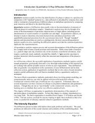
<strong>Metallography</strong> <strong>and</strong> <strong>Microstructures</strong> <strong>of</strong> <strong>Cast</strong> <strong>Iron</strong> / 567can be reduced to the desired size for metallographicspecimens by using a laboratory abrasivecut<strong>of</strong>f saw or a b<strong>and</strong> saw. If the casting wasFig. 7 Same as in Fig. 6 but after final polishing withthe 1 lm diamond paste applied on a naplesscloth. Graphite is free <strong>of</strong> any visible pullouts. As-polished.400sectioned by flame cutting, the specimen mustbe removed well away from the heat-affectedzone. The pieces cut out for metallographic examinationmay be ground prior to mounting (thismay be done to round <strong>of</strong>f sharp cut edges or toreduce the roughness <strong>of</strong> b<strong>and</strong>-saw-cut surfaces)<strong>and</strong> subsequent preparation. Overheating isavoided by proper selection <strong>of</strong> the speed <strong>of</strong> cut<strong>of</strong>fsaws, the use <strong>of</strong> the correct wheel, <strong>and</strong> adequatewater cooling. Overheating during grindingis avoided by using fresh abrasive paper <strong>and</strong>proper cooling. When metallographic specimensare cut out from the st<strong>and</strong>ard cast bars, they aresometimes prepared using st<strong>and</strong>ard machineshop equipment, such as turning in a lathe ormilling. These devices can deform the testpiecesurfaces to a considerable depth, so care must beexercised to remove any damage from theseoperations before starting specimen preparation.Mounting. Specimens can be mounted in apolymeric material using either cold or hotmounting procedures. The mounting resin ischosen depending on the cast iron hardness (s<strong>of</strong>tor hard) <strong>and</strong> the need to enhance edge retention.Use <strong>of</strong> an incorrect resin, or ignoring the mountingprocess, can make it very difficult to obtainproperly polished graphite in the area close tothe specimen edge. Figures 1 <strong>and</strong> 2 show themicrostructure <strong>of</strong> spheroidal graphite in ductileiron close to the edge <strong>of</strong> the specimens, whichwere cut <strong>of</strong>f from a 30 mm (1.2 in.) diameter bar<strong>and</strong> polished with <strong>and</strong> without embedding in apolymer resin, respectively. In the specimen preparedwithout embedding in a resin, the graphitewas pulled out, while in the specimen that wasembedded in a resin <strong>and</strong> prepared, the graphitenodules were perfectly retained. Figures 3 <strong>and</strong> 4show that the uniform grinding <strong>of</strong> nonmountedspecimens is more difficult, <strong>and</strong> the flake graphitein gray iron close to the edge <strong>of</strong> such a specimenis not polished perfectly, in comparison towell-polished graphite in the mounted specimen.Grinding <strong>and</strong> Polishing. To ensure propergraphite retention, the use <strong>of</strong> an automatedgrinding-polishing machine is recommendedover manual preparation. The automated equipmentmakes it possible, in comparison to manualspecimen preparation, to properly control theorientation <strong>of</strong> the specimen surface relative tothe grinding or polishing surface, to maintainconstantly the desired load on the specimens, touniformly rotate the specimens relative to thework surface, <strong>and</strong> to control the time for eachpreparation step. Proper control <strong>of</strong> these factorsinfluences graphite retention, although other factorsare also important.A good, general principle is to minimize thenumber <strong>of</strong> grinding <strong>and</strong> polishing stages. Also,the load on each specimen, or on all specimensin the holder, must be chosen to obtain a correctlypolished surface in the shortest possibletime. This precludes the risk <strong>of</strong> pulling out thegraphite phase <strong>and</strong> ensures that the graphite precipitateswill be perfectly flat with sharp boundaries.The recommended procedure for automatedpreparation <strong>of</strong> the specimens <strong>of</strong> nonalloyed <strong>and</strong>low-alloyed cast iron with graphite specimens isto grind with a high-quality, waterpro<strong>of</strong> 220- or240-grit (or equivalent) SiC paper until plane,with a load <strong>of</strong> 100 N for six specimens mountedin the sample holder, with central loading. Pol-Fig. 8 Same as in Fig. 7 but after final polishing withthe 1 lm diamond suspension applied on anapped cloth. The arrows show the pulled-out graphite.Aspolished.400Fig. 9 White high-chromium iron (Fe-3.2%C-4.65%Cr-2.9%Mn-0.51%Si-0.050%P-0.024%S). Eutectic<strong>and</strong> secondary carbides in the matrix. Specimen was preparedcorrectly. The casting was austenitized at 1000 C(1830 F), held 1 h, furnace cooled to 400 C (750 F) for2 h, taken to salt bath at 400 C (750 F), held for 4 h, <strong>and</strong>air cooled. Etched with glyceregia. 500Fig. 10 White high-chromium iron (Fe-3.16%C-8.86%Cr-0.50%Si-3.04%Mn-0.051%P-0.018%S). Eutectic <strong>and</strong> secondary carbides in the matrix.Specimen was prepared incorrectly. The casting was austenitizedat 1000 C (1830 F), held 1 h, furnace cooled to700 C (1290 F) for 2 h, taken to salt bath at 700 C (1290F), held 4 h, <strong>and</strong> air cooled. Etched with glyceregia. 500