WATER DISTRIBUTION RESPONSE IN A SOIL-ROOT SYSTEM ...
WATER DISTRIBUTION RESPONSE IN A SOIL-ROOT SYSTEM ...
WATER DISTRIBUTION RESPONSE IN A SOIL-ROOT SYSTEM ...

Create successful ePaper yourself
Turn your PDF publications into a flip-book with our unique Google optimized e-Paper software.
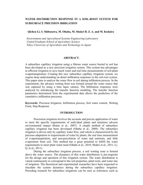
<strong>WATER</strong> <strong>DISTRIBUTION</strong> <strong>RESPONSE</strong> <strong>IN</strong> A <strong>SOIL</strong>-<strong>ROOT</strong> <strong>SYSTEM</strong> FORSUBSURFACE PRICISION IRRIGATIONQichen Li, S. Shibusawa, M. Ohaba, M. Shukri B. Z. A. and M. KodairaEnvironment and Agricultural Systems Engineering LaboratoryUnited Graduate School of Agriculture ScienceTokyo University of Agriculture and Technology in JapanABSTRACT:A subsurface capillary irrigation using a fibrous water source buried in soil hasbeen developed as a new precision irrigation system. This system has advantagesin efficient irrigation to save much water and real time measurements of soil-plantevapotranspiration. Creating this new subsurface capillary irrigation system, werequire deep understanding on detail infiltration responses in the soil-root system.This paper aims to analyze the water flow in soil during infiltration process. In theexperiments, the advance wetting front was formed around the water source thatwas captured by using a time lapse camera. The Infiltration responses wereanalyzed by introducing the transfer function modeling. The transfer functionparameters determined form the experimental data allows the prediction of thecumulative infiltration processes.Keywords: Precision Irrigation, Infiltration process, Soil water content, WettingFront, Step Response<strong>IN</strong>TRODUCTIONPrecession irrigation involves the accurate and precise application of waterto meet the specific requirements of individual plants and minimize adverseenvironmental impact (Raine et al., 2007). A simple method of subsurfacecapillary irrigation has been developed (Ohaba et al., 2009). The subsurfaceirrigation is driven only by capillary water flow, and which is characterized by theprecious adaptation to requirements of water by plants, the real time measurementof evapotranspiration, and non-percolation of water and nutrients, and littleevaporation from soil. This method has a great potential to fulfill the waterrequirements to meet plant water need (Ohaba et al., 2010; Shukri et al., 2011; Li,Q. et al., 2011).During the subsurface irrigation process, a soil wetting zone is formedabove the water source. The dynamics of this water distribution is pre-requisitefor the design and operation of this irrigation system. The water distribution isvaried continuously to correspond to the soil properties, plant roots, and water rateof irrigation. The theoretical and experimental researches have been requested toelucidate the system dynamics during the subsurface capillary irrigation.Preceding research for subsurface irrigations can be seen as references such as
elated infiltration analyses (Green and Ampt, 1911; Moltz et al, 1968; Philip1972; Al-Jabri et al., 2002) and irrigation system practices (Bresler et al., 1971;Vellids et al., 1990; Ah Koon et al., 1990). Further studies suggest the mutualinteraction between soil and water uptake by plants (Feddes et al., 1976; Malik etal., 1988). However, the irrigation techniques developed by us are different fromthose in conventional irrigations. Thus, further studies were plane to determinethe fundamental response of the water distribution to the adaptive control of theirrigation system.In present experimental study, we analyzed the horizontal infiltrationcaused by the capillary flow out from a sheet of a rectangular fibrous water source.This study was carried out for the aim to realize practical algorithm for theoptimal irrigation zone control in the subsurface irrigation. The transientresponses of the cumulative infiltration are reviewed to analyze the shape of watersphere and the cumulative water volume using the infiltration dynamiccharacteristics. The two dimensional infiltration will be analyzed using thetransfer functions.MATERIALS AND METHODSExperimental methodThe horizontal infiltration setup is shown in Fig. 1(a). The system iscomposed of a soil container, a water supply system, two electronic balances anda camera. The dimensions of the soil container made of clear acrylic plates are 40cm in width, 50 cm in length, and 6 cm in depth. The water supply systemconsists of a water level control tank with a reservoir and a water tank underneaththe soil container. Water was supplied through a sheet of a rectangular fibroussource (Toyobo, BKS0812G) which one end was buried in the soil and the otherput into the water supply tank. The water potential of the fibrous source is afunction of the water head h(t) that is controlled the displacement of a water levelby a mechatronics system using a labo-jack. A float in the water control tankenables to keep the water level at a constant value.Figure 1 (b) illustrates the top view of the horizontal soil plane with aCartesian coordinate system. The fibrous line source is located at the origin alongthe y-axis. The height of the source was 4 cm. Soil moisture sensors (Decagon,DC-5) are located at the different points P1 (x = 4cm), P2 (8cm) and P3 (12cm).The matric potential of the soil was measured by the tension meters at P1 and P2.The advance wetting front was monitored by a digital camera (Brinno,Gardenwatchcam) above the soil surface. The soil surface was covered with clearacrylic plates to stop the soil evaporation. The cumulative infiltration wasmeasured by an electronic balance (AND, GF-3000). The total water consumptionwas also measured by an electronic balance (AND, GX-06). The data wascaptured automatically by a data-logger (Graphic, GL820), and the data samplingtime was 5 minute. Karma clay soil was used in the experiment. The experimentwas conducted in a laboratory in Tokyo University of Agriculture andEngineering.
(a) Experimental setup(b)Top view of soil surfaceFig.1. Experimental Setup for horizontal infiltrationTheoretical back groundA well-known equation for water conservation is defined to analyze the dynamicwater flow during the infiltration process. This equation is shown in Eq. (1)ρ w V dddd = J ww − E s − E p (1)where θ(t) is the soil water content (SWC), J wi is the water inflow to the soil, ρ wis the density of water, V is the volume of water entry to the soil, E s and E p arethe water losses from the soil system caused by the soil evaporation and the planttranspiration, which does not contain in our experiment.For linear time invariant (LTI) systems, the transfer function models areintroduced to denote dynamic responses between selected inputs and outputs ofthe physical system. These modeling are used extensively in the field of controlsystem design because it is often the most effective way to incorporate LTI otherelements in otherwise physical computational model (Franklin et al., 1998).In our transfer function modeling, the first order transfer function of G(s)was used:K pG(s) = 1 + τ p s e−τ ds(2)where K p is the gain constant, τ p is the time constant, and τ d is the time lag.The step response of θ(t) for the input of the water head h(t) is given by:θ(t) = K p 1 − e −t−τ dτp H(t − τ d )∆u (3)where θ(t) is obtained from the inverse Laplace transform using Eq. (2),
H(t − τ d ) is the Heaviside function which is equal to 1 within t ≥ t d and 0 atother time, ∆u is the value of the step function.RESULTS & DISCUSSIONSFigure 2 shows the experimental matric potential and the volumetric watercontent curves for the Karma clay soil. The curve has a point of inflection. In Fig.2.the SWC gradient is changed at Ψ m = -230 cmH 2 O and increases from thispoint.Soil water content (m 3 /m -3 )0.50.40.30.20.10 200 400 600 800Matric Potential ( - cmH2O )Matric Potential (kpa)-80-60-40-20matric potential at4cmSoil Moisture at4cm0 2 4 6 8 1000Time ( h )0.50.40.30.20.1Soil water content (m3m-3)Fig.2 Soil characteristic functionFig.3 Matric potential and soil water contentFigure 3 shows the transient response of SWC and the matric potential. Ascan be observed, when the infiltration starts, SWC increases from the initial value10 % associated with the negative matric potential decrease from the maximalvalue -70kpa. After about 4 hours, SWC approaches to the saturated value 45%.The negative matric potential changes at about 2 hours when SWC is about 30%,and also approaches to the steady value -15kpa.Response of soil water contentFigure 4 shows the time variation of SWC at P1, P2. We can see the typical SWCstep responses in the horizontal infiltration. SWC at P1 increases from 10% at thebeginning of the infiltration and approaches to the saturated value of 45%. Thisresult suggests the first order response of infiltration. Thus we assume that theSWC responses might be determined based on transfer functions obtained fromthe experimental results.Table 1. Transfer function Parameters of step responses at each pointPosition K p (m 3 m -3 ) τ d (h) τ p (h)P1 0.36 1.08 0.50P2 0.36 4.10 1.25P3 0.36 7.93 1.90
that the experiment result is almost a linear function. It is clear that the estimatedvalues are well matched to the cumulative infiltration. This result indicates thatthe transfer function model is suitable for the prediction of water flow due to theinfiltration. It is feasible to use this finite difference method for the prediction ofcumulative infiltration.CONCLUSIONSThis study has observed and analyzed the horizontal infiltration process. Wheninfiltration starts, the soil water content increases associate with the soil matricpotential, and approaches to a steady state values. The transfer functions of soilwater content are determined, and the cumulative infiltration process is estimatedby the water conservation equation and transfer function modeling. The estimatedvalues are well matched with the experimental results. This shows the possibilityto use the transfer function for the prediction of soil water response. The dynamicwater flow in soil-root system will be continued based on the infiltration analysis.These data will be utilized to design of the process algorithm for the operation ofthe subsurface precision irrigation.REFERENCESAl-Jabri, S. A., Horton, H., and Jaynes, D. B., (2002). A point-source method forrapid simultaneous estimation of soil hydraulic and chemical transportproperties, Soil Science Society of American Journal, 66:12-18.Bresler, E., Heller, J., Dinner, N., Ben-Asher, I., Brandt, A., and Goldberg, D.,(1971), Infiltration Theoretical Predictions, Soil Science Society of AmericaProceedings, 35, 683-689.Feddes, R. A., Kowaliki, P., Malinka, K. K., and Zaradny, H., (1976), Simulationof Field Water-Uptake by Plants Using a Soil Water Dependent RootExtraction Function, Journal of Hydrology, 31, 13-26.Franklin, G. F., Powell J. D., and Workman M. L., Digital Control of DynamicSystems, Third Edition, Englewood Cliffs, NJ: Prentice-Hall, 1998.Green W H., and Ampt, G. A., (1911), Studies on Soil physics, I: Flow of Air andWater through Soils, Journal of Agriculture Science, 4, 1-24.Malik, R. K., Murty, V. V. N., and Narda, N. K., (1988), Soil Moisture Simulationunder Cropped Condition Using a Moisture Dependent Root Sink Function,Journal of Agronomy and Crop Science, 161, 166-170.Li, Q., Ohaba, M., Shukuri, M., Kodaira, M., and Sibusawa, S, (2011),Rhizosphere Moisture Control of Tomato During Subsurface Irrigation, Proc.Fourth Asian Conference of Precision Agriculture,Obihiro, Japan, 4 pages.Moltz, F. J., Remson, I., Fungeroli, A. A., and Dake, R. K., (1968), WaterResources Research, 4, 1161-1169.Ohaba, M., Hosoya, H., and Ikeda, N., (2008), Real Time Measurement of WaterAbsorption of Plants Using Subsurface Negative Pressure Irrigation, Proc.Int. Conf Sustainable Agriculture for Food Energy and Industry, 391-394.Ohaba, M., Shibusawa, S., Hosoya, H., (2010), Rhizophere Moisture Modulation
y Water Head Precession Control. Proc.10 th International Conference ofPrecision Agriculture, Denver USA, 4 Pages (CD-ROM).Philip, J. R., (1972), Steady Infiltration from Buried, Surface and Perched Pointand Line Sources in Heterogeneous Soils, I: Analysis, Soil Science Society ofAmerica Proceedings, 36, 268-273.Raine, S.R., Meyer, W.S., Rassam, D.W., Hutson J.L. and Cook, F.J (2007),Soil-Water and Solute Movement under Precision Irrigation-Knowledge gapsfor managing sustainable root zones, Irrigation Science, 26, 91-100.Shukri, M., Ohaba M., Shibusawa S., Kodaira M., Li Q., and Khalid M., (2011),Plant Growth and Water Absorption Data for Subsurface Precision Irrigation,Proc. Fourth Asian Conference on Precision Agriculture, Obihiro, Japan.Vellids, G., Smajstrla, A. G., and Zazueta, F. S., (1990), Soil Water Redistributionand Extraction Patterns of Drip Irrigated Tomatoes above a Shallow WaterTable, Transactions of the America Society of Agricultural Engineers, 33(5),1525-1530.