LA1844 - FM-AM HF Amplifiers - maxdat.eu
LA1844 - FM-AM HF Amplifiers - maxdat.eu
LA1844 - FM-AM HF Amplifiers - maxdat.eu

Create successful ePaper yourself
Turn your PDF publications into a flip-book with our unique Google optimized e-Paper software.
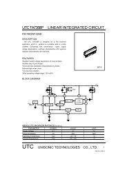
Ordering number : EN7930A<strong>LA1844</strong><strong>LA1844</strong>MMonolithic Linear ICFor Home StereoSingle-chip Tuner ICOverviewThe <strong>LA1844</strong>, <strong>LA1844</strong>M is designed for use in mini systems and is a single-chip tuner IC that provides electronic tuningfunctions using SD/IF-count technique. It incorporates a pilot canceler and an adjustment-free MUX VCO circuit, thusallows additional parts to be reduced.Features• Integrated MPX VCO (ceramic resonators are no longer required.)• Built-in adjacent channel interference rejection function (114kHz, 190kHz)• Supports both SD and IF-count techniques• Both <strong>FM</strong> SD sensitivity and bandwidth can be set• Pilot canceler built in.• Package : DIP24S(300mil) [<strong>LA1844</strong>], MFP24S(300mil) [<strong>LA1844</strong>M]Functions• <strong>AM</strong> : RF amplifier, mixer, oscillator, IF amplifier, detector, AGC, SD, oscillator buffer, IF buffer, stereo IF output,AGC time constant switch• <strong>FM</strong> IF : IF amplifier, quadrature detector, S-meter, SD (signal detection), S-curve detection, IF buffer output• MPX : PLL stereo decoder, stereo display, forced monaural, VCO stop, audio muting, adjacent channel interferencerejection function, pilot cancelerAny and all SANYO Semiconductor products described or contained herein do not have specificationsthat can handle applications that require extremely high levels of reliability, such as life-support systems,aircraft's control systems, or other applications whose failure can be reasonably expected to result inserious physical and/or material damage. Consult with your SANYO Semiconductor representativenearest you before usingany SANYO Semiconductor products described or contained herein in suchapplications.SANYO Semiconductor assumes no responsibility for equipment failures that result from using productsat values that exceed, even momentarily, rated values (such as maximum ratings, operating conditionranges, or other parameters) listed in products specifications of any and all SANYO Semiconductorproducts described or contained herein.83006 / 52106 MS OT B8-7111 No.7930A-1/11
<strong>LA1844</strong>,<strong>LA1844</strong>MSpecificationsMaximum Ratings at Ta = 25°CParameter Symbol Conditions Ratings UnitMaximum supply voltage V CC max 9 VAllowable power dissipationPd maxTa ≤ 45°C 400 mWTa ≤ 80°C 260 mWOperating temperature Topr -20 to +80 °CStorage temperature Tstg -20 to +150 °COperating Conditions at Ta = 25°CParameter Symbol Conditions Ratings UnitRecommended supply voltage V CC 5 VOperating supply voltage range V CC op 4.3 to 8.0 VElectrical Characteristics at Ta = 25°C<strong>FM</strong> Mono Characteristics at fC = 10.7MHz, VCC = 5VRatingsParameter Symbol Conditionsmin typ maxUnitCurrent drain I CCO-<strong>FM</strong> With no input signal 18 28 38 mADemodulator output V O<strong>FM</strong> 100dBµ, 100% modulation, fm = 1kHz 210 330 420 mVrmsTotal harmonic distortion THD <strong>FM</strong> mono 100dBµ, 100% modulation, fm = 1kHz 0.35 1.5 %Signal-to-noise ratio S/N <strong>FM</strong> 100dBµ, 100% modulation, fm = 1kHz 73 80 dB<strong>AM</strong> rejection ratio <strong>AM</strong>R 100dBµ, <strong>AM</strong> 30% modulation, fm = 1kHz 47 65 dB3dB sensitivity Vi-limit 100dBµ, 100% modulation,32 40 dBµfm = 1kHz output reference, -3dB inputSD sensitivity LED Sens 0% modulation 37 47 57 dBµIF counter buffer output V IFBuff-<strong>FM</strong> 100dBµ 200 275 400 mVrmsMute attenuation Mute-Att 100dBµ, 100% modulation, fm = 1kHz 76 dB<strong>FM</strong> Stereo Characteristics at fC = 10.7MHz, 100dBµ, VCC = 5VRatingsParameter Symbol Conditionsmin typ maxUnitSeparation Sep L+R = 90%, Pilot = 10%, fm = 1kHz 30 42 dBStereo on level ST ON Pilot input 1.5 3.5 5.5 %Total harmonic distortion THD-main Pilot input 0.45 1.5 %Adjacent channel rejection ratio 1 BR1 fs = 113kHz, Vs = 90%, pilot = 10% :36 dBThe left - right modulation, demodulated outputAdjacent channel rejection ratio 2 BR2 fs = 189kHz, Vs = 90%, pilot = 10% :41 dBThe left - right modulation, demodulated outputCarrier leak CL L+R = 90%, pilot = 10% reference,pilot = 10% output38 44 dB<strong>AM</strong> Characteristics at fC = 1000kHz, VCC = 5VRatingsParameter Symbol Conditionsmin typ maxUnitCurrent drain I CCO-<strong>AM</strong> With no input signal 11 22 33 mADetector outputV O<strong>AM</strong>1 23dBµ, 30% modulation, fm = 1kHz 40 80 160 mVrmsV O<strong>AM</strong>2 80dBµ, 30% modulation, fm = 1kHz 90 160 230 mVrmsSignal-to-noise ratioS/N <strong>AM</strong>1 23dBµ, 30% modulation, fm = 1kHz 17 23 dBS/N <strong>AM</strong>2 80dBµ, 30% modulation, fm = 1kHz 48 54 dBTotal harmonic distortionTHD <strong>AM</strong>1 80dBµ, 30% modulation, fm = 1kHz 0.4 1.1 %THD <strong>AM</strong>2 107dBµ, 30% modulation, fm = 1kHz 0.5 1.3 %SD sensitivity SD-Sens 0% modulation 11 21 31 dBµLocal oscillator buffer output V OSC-<strong>AM</strong> With no input signal 100 140 200 mVrmsIF counter buffer output V IFBuff-<strong>AM</strong> 23dBµ 140 285 400 mVrmsNo.7930A-2/11
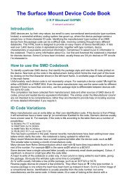
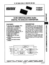
<strong>LA1844</strong>,<strong>LA1844</strong>MPackage Dimensionsunit : mm3067B [1844M]3112B [<strong>LA1844</strong>]21.024 132412.5136.47.625.47.61 120.251 120.633.3 3.9 max0.51min(3.25)(0.71)0.90.951.78 0.48SANYO : DIP24S(300mil)(0.75)1.0 0.350.150.1 (1.5)1.7maxSANYO : MFP24S(300mil)No.7930A-3/11
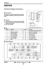
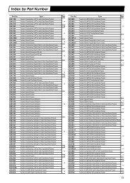
Block Diagram<strong>LA1844</strong>,<strong>LA1844</strong>MNo.7930A-4/11
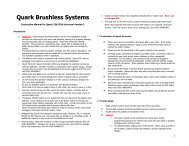
<strong>LA1844</strong>,<strong>LA1844</strong>MContinued from preceding page.Pin No.FunctionPin voltage(V)Equivalent circuitNotes12 Pilot detectorlow-pass filter(Forced mono)(VCO stop)V CC -1.0The device is forced to monaural when a current ofover 50µA flows from this pin.The VCO is stopped when a current of over 200µAflows from this pin.1314L outputsR outputs3.2 Output impedance R O = 3.3kΩ15 Pilot canceleroutputVreg16 Decoder input Vreg Inverting input pinRNF = 20kΩ17 PLL input Vreg Input impedance R i = 20kΩ18 <strong>FM</strong> demodulatoroutputVreg+0.7Output impedance R O = 2.3kΩThe channel separation can be adjusted with anexternal capacitor connected between this pin andground.19 <strong>AM</strong> detectoroutput0 (<strong>FM</strong>)1.5 (<strong>AM</strong>)Output impedance R O = 3.3kΩ20 S meter,<strong>AM</strong> AGC0.2 (<strong>FM</strong>)0.9 (<strong>AM</strong>)The resistance of the built-in resistor R is 13.9kΩThe SD responce during seek operation isdetermined with the external capacitor connectedto this pin.Continued on next page.No.7930A-7/11
Continued from preceding page.Pin No.FunctionPin voltage(V)<strong>LA1844</strong>,<strong>LA1844</strong>MEquivalent circuit21 <strong>AM</strong> RF input Vreg Must be used at the same potential as pin 22Notes22 AFC Vreg The <strong>FM</strong> SD bandwidth can be adjusted with theexternal resistor connected between this pin andpin 3 (REG)23 OSC V CC Connect the oscillator coil between this pin andpin 9 (V CC )Note: Impedance of the secondary oscillator coilmust be 5kΩ or higher.24 Oscillator bufferoutput,<strong>FM</strong> SD sensitivityadjustmentV CC -1.4The <strong>FM</strong> SD sensitivity can be adjusted with anexternal resistor connected to this pin.Output impedance R O = 200ΩNote: Resistance of the external resistorconnected to the pin 24 must be 3.3kΩor higher.No.7930A-8/11
<strong>LA1844</strong>,<strong>LA1844</strong>MNo.7930A-9/11