Burr Brown PCM1738 - 24-Bit, 192kHz Sampling.pdf - MaxDat
Burr Brown PCM1738 - 24-Bit, 192kHz Sampling.pdf - MaxDat
Burr Brown PCM1738 - 24-Bit, 192kHz Sampling.pdf - MaxDat

Create successful ePaper yourself
Turn your PDF publications into a flip-book with our unique Google optimized e-Paper software.
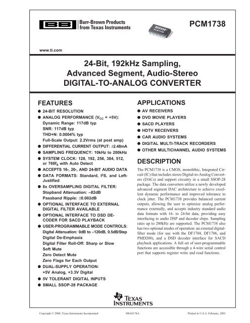
SPECIFICATIONSAll specifications at T A = +25°C, V DD = +3.3V, V CC = +5V, SCKI = 256f S (f S = 44.1kHz), and <strong>24</strong>-bit input data, unless otherwise noted.<strong>PCM1738</strong>EPARAMETER CONDITIONS MIN TYP MAX UNITSRESOLUTION <strong>24</strong> <strong>Bit</strong>sDATA FORMATAudio Data Interface FormatsStandard, I 2 S, Left-JustifiedAudio Data <strong>Bit</strong> Length16-, 20-, <strong>24</strong>-<strong>Bit</strong>s SelectableAudio Data FormatMSB-First, Binary Two’s Complement<strong>Sampling</strong> Frequency (f S ) 10 200 kHzSystem Clock Frequency128, 192, 256, 384, 512, 768f SDIGITAL INPUT/OUTPUTLogic FamilyTTL-CompatibleInput Logic LevelV IH 2.0 VDCV IL 0.8 VDCInput Logic CurrentI IH V IN = V DD 10 µAI IL V IN = 0V –10 µAOutput Logic LevelV OH I OH = –2mA 2.4 VDCV OL I OL = +2mA 1.0 VDCHigh Impedance Output Logic Current (1)I OHZ V OUT = V DD 5 µAI OLZ V OUT = V DD 5 µADYNAMIC PERFORMANCE (2)THD+N at V OUT = 0dB f S = 44.1kHz 0.0004 0.0008 %f S = 96kHz 0.0006 %f S = <strong>192kHz</strong> 0.0012 %Dynamic Range EIAJ, A-Weighted, f S = 44.1kHz 114 117 dBA-Weighted, f S = 96kHz 117 dBA-Weighted, f S = <strong>192kHz</strong> 117 dBSignal-to-Noise Ratio EIAJ, A-Weighted, f S = 44.1kHz 114 117 dBA-Weighted, f S = 96kHz 117 dBA-Weighted, f S = <strong>192kHz</strong> 117 dBChannel Separation f S = 44.1kHz 110 115 dBf S = 96kHz 113 dBf S = <strong>192kHz</strong> 111 dBLevel Linearity Error V OUT = –110dB ±1.0 dBDC ACCURACYV COM 2 Voltage 2.45 VV COM 2 Output Current Delta V COM 2 < 5% 100 µAGain Error ±2.0 % of FSRGain Mismatch, Channel-to-Channel ±0.5 % of FSRBipolar Zero Error at Bipolar Zero ±0.5 % of FSRDSD MODE DYNAMIC PERFORMANCE (1)44.1kHz, 64f STHD+N at Full Scale ±2.48mAp-p 0.0004 %Dynamic Range –60dB, EIAJ, A-Weighted 117 dBSignal-to-Noise Ratio EIAJ, A-Weighted 117 dBANALOG OUTPUTOutput Current Full Scale (0dB) ±2.48 mAp-pDSD Mode Output Current 100% OUTPUT ±2.48 mAp-pCenter Current Bipolar Zero Input 0 mAp-pDIGITAL-FILTER PERFORMANCEFilter Characteristics 1, Sharp Roll-OffPassband ±0.002dB 0.454f S HzPassband –3dB 0.487f S HzStopband 0.546f S HzPassband Ripple ±0.002 dBStopband Attenuation Stopband = 0.546f S –75 dBStopband Attenuation Stopband = 0.567f S –82 dBFilter Characteristics 2, Slow Roll-OffPassband ±0.04dB 0.274f S HzPassband –3dB 0.454f S HzStopband 0.732f S HzPassband Ripple ±0.002 dBStopband Attenuation Stopband = 0.732f S –82 dBDelay Time 29/f S secDe-Emphasis Error ±0.1 dB2<strong>PCM1738</strong>SBAS174A
SPECIFICATIONS (Cont.)All specifications at T A = +25°C, V DD = +3.3V, V CC = +5V, SCKI = 256f S (f S = 44.1kHz), and <strong>24</strong>-bit input data, unless otherwise noted.<strong>PCM1738</strong>EPARAMETER CONDITIONS MIN TYP MAX UNITSPOWER SUPPLY REQUIREMENTSVoltage Range, V DD +3.0 +3.3 +3.6 VDCV CC +4.75 +5.0 +5.25 VDCSupply Current, I (4) DD V DD = 3.3V, f S = 44.1kHz 7.0 9.8 mAV DD = 3.3V, f S = 96kHz 15.0 mAV DD = 3.3V, f S = <strong>192kHz</strong> 30.0 mAI CC V CC = 5.0V, f S = 44.1kHz 33.0 46.2 mAV CC = 5.0V, f S = 96kHz 34.5 mAV CC = 5.0V, f S = <strong>192kHz</strong> 36.5 mAPower Dissipation V DD = 3.3V, V CC = 5.0V, f S = 44.1kHz 188 263 mWV DD = 3.3V, V CC = 5.0V, f S = 96kHz 222 mAV DD = 3.3V, V CC = 5.0V, f S = <strong>192kHz</strong> 282 mWTEMPERATURE RANGEOperation Temperature –25 +85 °CThermal Resistance θ JA SSOP-28 115 °C/WNOTES: (1) Pin 11 (MDO). (2) Analog performance specifications are measured by an Audio Precision System II, using an averaging mode. At 44.1kHzoperation, bandwidth measurement is limited with 20kHz. At 96kHz and <strong>192kHz</strong>, bandwidth measurement is limited with 40kHz. (3) Theoretical performancein DSD modulation index of 100%. It's performance is equivalent to the PCM mode. (4) SCKO is disabled. Input is Bipolar Zero Data.ABSOLUTE MAXIMUM RATINGSPower Supply Voltage, V CC 1, V CC 2, and V CC 3 .............................................. +6.5VV DD ............................................................................. +4.0VSupply Voltage Differences Among V CC 1, V CC 2, and V CC 3 .......................... ±0.1VGround Voltage Differences Among AGND1, AGND2,and AGND3 ................................................................................................. ±0.1VDigital Input Voltage, LRCK, DATA, BCK, SCKI, MDI,MC, and MUTE ............................................................................... –0.3V to 6.5VDigital Input Voltage, ZEROL, ZEROR, SCKO,and MDO ........................................................................... –3.0V to (V DD + 0.3V)Analog Input Voltage, I OUT R–, I OUT R+, V COM 1,V COM 2, V COM 3, I REF , I OUT L+, and I OUT L– ................ –0.3V to (V CC , V CC 2 + 0.3V)Input Current (except power supply) ............................................................ ±10mAAmbient Temperature Under Bias ................................................ –40°C to +125°CStorage Temperature .................................................................... –55°C to +150°CJunction Temperature .................................................................................. +150°CELECTROSTATICDISCHARGE SENSITIVITYThis integrated circuit can be damaged by ESD. <strong>Burr</strong>-<strong>Brown</strong>recommends that all integrated circuits be handled withappropriate precautions. Failure to observe proper handlingand installation procedures can cause damage.ESD damage can range from subtle performance degradationto complete device failure. Precision integrated circuits maybe more susceptible to damage because very small parametricchanges could cause the device not to meet its publishedspecifications.PACKAGE/ORDERING INFORMATIONPACKAGESPECIFIEDDRAWING TEMPERATURE PACKAGE ORDERING TRANSPORTPRODUCT PACKAGE NUMBER RANGE MARKING NUMBER (1) MEDIA<strong>PCM1738</strong>E SSOP-28 3<strong>24</strong> –25°C to +85°C <strong>PCM1738</strong>E <strong>PCM1738</strong>E Rails" " " " " <strong>PCM1738</strong>E/2K Tape and ReelNOTE: (1) Models with a slash (/) are available only in Tape and Reel in the quantities indicated (e.g., /2K indicates 2000 devices per reel). Ordering 2000 piecesof “<strong>PCM1738</strong>E/2K” will yield a single 2000-piece Tape and Reel.<strong>PCM1738</strong> 3SBAS174A
V CC 1BLOCK DIAGRAMLRCKDATABCKInputI/FCurrentSegmentDACI OUT L+I OUT L–RSTMUTECSMCFunctionControl8xOversamplingDigitalFilterandFunctionControlAdvancedSegmentDACModulatorBiasand V REFV COM 2I REFV COM 1V COM 3IV and FilterIV and FilterMDIMDOI/FCurrentSegmentDACI OUT R–I OUT R+System ClockSCKISystem ClockManagerZERO DetectPower SupplyV CC2SCKOZEROLZERORV DDDGNDV CC 3AGND1AGND2PIN CONFIGURATIONPIN ASSIGNMENTSTOP VIEWSSOPPIN NAME TYPE FUNCTIONRSTZEROLZERORLRCKDATABCKSCKIDGNDV DDSCKOMDOMDIMCCS1234567891011121314<strong>PCM1738</strong>28272625<strong>24</strong>232221201918171615V CC 3AGND2I OUT L–I OUT L+V CC 2V CC 1V COM 3I REFV COM 2V COM 1AGND1I OUT R+I OUT R–MUTE1 RST IN Reset (1)2 ZEROL OUT Zero Flag for L-Channel.3 ZEROR OUT Zero Flag for R-Channel.4 LRCK IN Left/Right clock (f S ) input for normal operation. (1)WDCK clock input in external DF mode. Connectedto GND in DSD mode.5 DATA IN Serial Audio data input for normal operation. (1)L-channel audio data input for external DF andDSD modes.6 BCK IN <strong>Bit</strong> Clock. Input. Connected to GND for DSD mode. (1)7 SCKI IN System Clock Input for normal operation. (1)BCK (64f S ) clock input for DSD mode.8 DGND – Digital Ground9 V DD – Digital Supply, +3.3V10 SCKO OUT System Clock Output11 MDO OUT Serial data output for function control register. (2)12 MDI IN Serial data input for function control register. (1)13 MC IN Shift Clock for function control register. (1)14 CS IN Mode Control chip select and latch signal. (1)15 MUTE IN Analog output mute control for normal operation. (1)R-channel audio data input for external DF andDSD modes.16 I OUT R– OUT R-Channel Analog Current Output –17 I OUT R+ OUT R-Channel Analog Current Output +18 AGND1 – Analog Ground19 V COM 1 – Internal Bias Decoupling Pin20 V COM 2 – Common Voltage for I/V21 I REF – Output current reference bias pin. Connect 16kΩresistor to GND.22 V COM 3 – Internal Bias Decoupling Pin23 V CC 1 – Analog Supply, +5.0V<strong>24</strong> V CC 2 – Analog Supply, +5.0V25 I OUT L+ OUT L-Channel Analog Current Output +26 I OUT L– OUT L-Channel Analog Current Output –27 AGND2 – Analog Ground28 V CC 3 – Analog Power Supply, +5.0VNOTES: (1) Schmitt-trigger input, 5V tolerant. (2) Tristate output.4<strong>PCM1738</strong>SBAS174A
TYPICAL PERFORMANCE CURVESAll specifications at T A = +25°C, V DD = +3.3V, V CC = +5V, SCKI = 256f S (f S = 44.1kHz), and <strong>24</strong>-bit input data, unless otherwise noted.DIGITAL FILTERDigital Filter (De-Emphasis Off, f S= 44.1kHz)0FREQUENCY RESPONSE (Sharp Roll-Off)0.003PASSBAND RIPPLE (Sharp Roll-Off)Amplitude (dB)–20–40–60–80–100–120–140Amplitude (dB)0.0020.0010–0.001–0.002–1600 1 2 3 4Frequency (x f S)–0.0030 0.1 0.2 0.3 0.4 0.5Frequency (x f S )0FREQUENCY RESPONSE (Slow Roll-Off)0TRANSITION CHARACTERISTICS (Slow Roll-Off)–20–40–2–4–6Amplitude (dB)–60–80–100Amplitude (dB)–8–10–12–14–120–16–18–1400 1 2 3 4Frequency (x f S)–200 0.1 0.2 0.3 0.4 0.5 0.6Frequency (x f S)De-Emphasis Error0.0DE-EMPHASIS (f S = 32kHz)0.5DE-EMPHASIS ERROR (f S = 32kHz)–1.00.4–2.00.3–3.00.2Level (dB)–4.0–5.0–6.0–7.0Error (dB)0.10.0–0.1–0.2–8.0–0.3–9.0–0.4–10.00 2 4 6 8 10 12 14Frequency (kHz)–0.50 2 4 6 8 10 12 14Frequency (kHz)<strong>PCM1738</strong> 5SBAS174A
TYPICAL PERFORMANCE CURVES (Cont.)All specifications at T A = +25°C, V DD = +3.3V, V CC = +5V, SCKI = 256f S (f S = 44.1kHz), and <strong>24</strong>-bit input data, unless otherwise noted.De-Emphasis Error (Cont.)0.0DE-EMPHASIS (f S= 44.1kHz)0.5DE-EMPHASIS ERROR (f S= 44.1kHz)–1.00.4–2.00.3–3.00.2Level (dB)–4.0–5.0–6.0Error (dB)0.10.0–0.1–7.0–0.2–8.0–0.3–9.0–0.4–10.0–0.50 2 4 6 8 10 12 14 16 18 200 2 4 6 8 10 12 14 16 18 20Frequency (kHz)Frequency (kHz)0.0DE-EMPHASIS (f S= 48kHz)0.5DE-EMPHASIS ERROR (f S= 48kHz)–1.00.4–2.00.3–3.00.2Level (dB)–4.0–5.0–6.0Error (dB)0.10.0–0.1–7.0–0.2–8.0–0.3–9.0–0.4–10.0–0.50 2 4 6 8 10 12 14 16 18 220 2 4 6 8 10 12 14 16 18 22Frequency (kHz)Frequency (kHz)ANALOG DYNAMIC PERFORMANCEAll specifications at T A = +25°C, V DD = +3.3V, V CC = +5V, SCKI = 256f S (f S = 44.1kHz), and <strong>24</strong>-bit input data, unless otherwise noted.Analog Dynamic Performance0.0020THD+N/f Svs V CC0.0020THD+N/f S vs TEMPERATURE0.001544.1 kHz96kHz0.001544.1 kHz96kHzTHD+N/f S (%)0.0010THD+N/f S (%)0.00100.00050.0005004.50 4.75 5.00 5.25 5.50–40 –20 0 20 40 60 80 100V CC (V)Temperature (°C)6<strong>PCM1738</strong>SBAS174A
TYPICAL PERFORMANCE CURVES (Cont.)All specifications at T A = +25°C, V DD = +3.3V, V CC = +5V, SCKI = 256f S (f S = 44.1kHz), and <strong>24</strong>-bit input data, unless otherwise noted.Analog Dynamic Performance (Cont.)120DYNAMIC RANGE vs V CC120DYNAMIC RANGE vs TEMPERATURE119119Dynamic Range (dB)11811711611511444.1 kHz96kHzDynamic Range (dB)11811711611511444.1 kHz96kHz11311311<strong>24</strong>.50 4.75 5.00 5.25 5.50V CC(V)112–40 –20 0 20 40 60 80 100Temperature (°C)120SIGNAL-TO-NOISE RATIO vs V CC120SIGNAL-TO-NOISE RATIO vs TEMPERATURE119119118118117117SNR (dB)116115SNR (dB)11611511444.1 kHz96kHz11444.1 kHz96kHz11311311<strong>24</strong>.50 4.75 5.00 5.25 5.50V CC (V)112–40 –20 0 20 40 60 80 100Temperature (°C)118CHANNEL SEPARATION vs V CC118CHANNEL SEPARATION vs TEMPERATURE11744.1 kHz96kHz11744.1 kHz96kHzChannel Separation (dB)116115114113112Channel Separation (dB)1161151141131121111111104.50 4.75 5.00 5.25 5.50V CC (V)110–40 –20 0 20 40 60 80 100Temperature (°C)<strong>PCM1738</strong> 7SBAS174A
TYPICAL PERFORMANCE CURVES (Cont.)All specifications at T A = +25°C, V DD = +3.3V, V CC = +5V, SCKI = 256f S (f S = 44.1kHz), and <strong>24</strong>-bit input data, unless otherwise noted.Analog Dynamic Performance (Cont.)0–60dB OUTPUT SPECTRUM (BW = 20kHz)0–60dB OUTPUT SPECTRUM (BW = 100kHz)–20–20–40–40Output Level (dB)–60–80–100–120Output Level (dB)–60–80–100–120–140–140–160–1600 5k 10k 15k 20k0 20k 40k 60k 80k 100kFrequency (Hz)Frequency (Hz)100THD+N vs LEVEL (PCM MODE)100THD+N vs LEVEL (DSD MODE)1044.1 kHz96kHz1011THD+N (%)0.10.01THD+N (%)0.10.010.0010.0010.00010.0001–100 –80 –60 –40 –20 0–100 –80 –60 –40 –20 0Level ( ?)Level ( ?)0–60dB OUTPUT SPECTRUM ON DSD MODE–20–40Output Level (dB)–60–80–100–120–140–1600 5k 10k 15k 20kFrequency (Hz)8<strong>PCM1738</strong>SBAS174A
ANALOG FIR FILTER PERFORMANCE FOR DSD MODEAll specifications at T A = +25°C, V DD = +3.3V, V CC = +5V, SCKI = 11.2896MHz (44.1kHz • 256fS), and 50% modulation DSD data input, unless otherwise noted.0DSD FILTER 10DSD FILTER 1–1–20Gain (dB)–2–3–4Gain (dB)–40–60–5–80–60 50 100 150 200Frequency (kHz)–1000 500 1000 1500Frequency (kHz)0DSD FILTER 20DSD FILTER 2–1–20Gain (dB)–2–3–4Gain (dB)–40–60–5–80–60 50 100 150 200Frequency (kHz)–1000 500 1000 1500Frequency (kHz)0DSD FILTER 30DSD FILTER 3–1–20Gain (dB)–2–3–4Gain (dB)–40–60–5–80–60 50 100 150 200Frequency (kHz)–1000 500 1000 1500Frequency (kHz)<strong>PCM1738</strong> 9SBAS174A
ANALOG FIR FILTER PERFORMANCE FOR DSD MODE (Cont.)All specifications at T A = +25°C, V DD = +3.3V, V CC = +5V, SCKI = 11.2896MHz (44.1kHz • 256fS), and 50% modulation DSD data input, unless otherwise noted.0DSD FILTER 40DSD FILTER 4–1–20Gain (dB)–2–3–4Gain (dB)–40–60–5–80–60 50 100 150 200Frequency (kHz)–1000 500 1000 1500Frequency (kHz)10<strong>PCM1738</strong>SBAS174A
SYSTEM CLOCK AND RESETFUNCTIONSSYSTEM CLOCK INPUTThe <strong>PCM1738</strong> requires a system clock for operating thedigital interpolation filters and advanced segment DACmodulators. The system clock is applied at the SCKI input(pin 7). The <strong>PCM1738</strong> has a system-clock detection circuitthat automatically senses if the system clock is operating at128f S to 768f S . Table I shows examples of system-clockfrequencies for common audio sampling rates.Figure 1 shows the timing requirements for the system clockinput. For optimal performance, it is important to use a clocksource with low phase jitter and noise. The PLL1700 multiclockgenerator is an excellent choice for providing the<strong>PCM1738</strong> system clock.SYSTEM CLOCK OUTPUTA buffered version of the system clock input is available atthe SCKO output (pin 10). SCKO can operate at either full(f SCKI ) or half (f SCKI /2) rate. The SCKO output frequencymay be programmed using the CLKD bit of Control Register19. The SCKO output pin can also be enabled or disabledusing the CLKE bit of Control Register 19. The default isSCKO enabled.POWER-ON AND EXTERNAL RESET FUNCTIONSThe <strong>PCM1738</strong> includes a power-on reset function (seeFigure 2). The system clock input at SCKI should be activefor at least one clock period prior to V DD = 2.0V. With thesystem clock active, and V DD > 2.0V, the power-on resetfunction will be enabled. The initialization sequence requires10<strong>24</strong> system clocks from the time V DD > 2.0V. Afterthe initialization period, the <strong>PCM1738</strong> will be set to its resetdefault state, as described in the Mode Control Registersection of this data sheet.The <strong>PCM1738</strong> also includes an external reset capabilityusing the RST input (pin 1). This allows an external controlleror master reset circuit to force the <strong>PCM1738</strong> to initializeto its reset default state.See Figure 3 for external reset operation and timing. TheRST pin is set to a logic “0” for a minimum of 20ns. TheRST pin is then set to a logic “1” state that starts theinitialization sequence that requires 10<strong>24</strong> system clock periods.After the initialization sequence is complete, the<strong>PCM1738</strong> will be set to its reset default state, as describedin the Mode Control Register section of this data sheet.The external reset is especially useful in applications wherethere is a delay between the <strong>PCM1738</strong> power-up and systemclock activation. In this case, the RST pin should be held ata logic “0” level until the system clock has been activated.The RST pin may then be set to a logic “1” state to start theinitialization sequence.SYSTEM CLOCK FREQUENCY (f SCLK ) (MHz)SAMPLINGFREQUENCY 128f S 192f S 256f S 384f S 512f S 768f S32kHz 4.0960 6.1440 8.1920 12.2880 16.3840 <strong>24</strong>.576044.1kHz 5.6488 8.4672 11.2896 16.9344 22.5792 33.868848kHz 6.1440 9.2160 12.2880 18.4320 <strong>24</strong>.5760 36.864096kHz 12.2880 18.4320 <strong>24</strong>.5760 36.8640 49.1520 73.7280<strong>192kHz</strong> <strong>24</strong>.5760 36.8640 49.1520 73.7280 See Note (1) See Note (1)NOTE: (1) This system clock is not supported for the given sampling frequency.TABLE I. System Clock Rates for Common Audio <strong>Sampling</strong> Frequencies.t SCKHSystem Clock“H”“L”2.0V0.8Vt SCKLSystem clock pulsecycle time (1)System Clock Pulse Width HIGH t SCKH: 7ns (min)System Clock Pulse Width LOW t SCKL : 7ns (min)FIGURE 1. System Clock Input Timing.<strong>PCM1738</strong> 11SBAS174A
t RSTReset Reset RemovalV DD2.4V/max2.0V/typ1.6V/minInternal ResetSystem ClockReset10<strong>24</strong> System Clock PeriodsReset RemovalFIGURE 2. Power-On Reset Timing.RST (pin 1)50% of V DDInternal Reset10<strong>24</strong> System ClocksSystem ClockReset Pulse Width LOW t RST 20ns (min)FIGURE 3. Audio Data Input Formats.AUDIO DATA INTERFACEAUDIO SERIAL INTERFACEThe audio serial interface for the <strong>PCM1738</strong> is comprised ofa 3-wire synchronous serial port. It includes LRCK (pin 4),BCK (pin 6), and DATA (pin 5). BCK is the serial audio bitclock, used to clock the serial data present on DATA into theaudio interface’s serial shift register. Serial data is clockedinto the <strong>PCM1738</strong> on the rising edge of BCK. LRCK is theserial audio left/right word clock, used to latch serial datainto the serial audio interface’s internal registers.LRCK should be synchronous to the system clock. In theevent these clocks are not synchronized, the <strong>PCM1738</strong> cancompensate for the phase difference internally. If the phasedifference between LRCK and SCKI is greater than six bitclocks (BCK), the synchronization is performed internally.While the synchronization is processing, the analog output isforced to the bipolar zero level. The synchronization typicallyoccurs in less than one cycle of LRCK.Ideally, it is recommended that LRCK and BCK be derivedfrom the system clock input or output, SCKI or SCKO. Theleft/right clock (LRCK) is operated at the sampling frequency,f S .AUDIO DATA FORMATS AND TIMINGThe <strong>PCM1738</strong> supports industry-standard audio data formats,including Standard Right-Justified, I 2 S, and Left-Justified. Thedata formats are shown in Figure 4. Data formats are selectedusing the format bits, FMT [2:0], in Control Register 18. Thedefault data format is 16-bit Standard. All formats requireBinary Two’s Complement, MSB-first audio data. Figure 5shows a detailed timing diagram for the serial audio interface.12<strong>PCM1738</strong>SBAS174A
(1) Standard Data Format (Right Justified): L-Channel = HIGH, R-Channel = LOW1/f SLRCKBCKL-ChannelR-ChannelAudio Data Word = 16 <strong>Bit</strong>DATA14 15 161 215 161 215 16Audio Data Word = 20 <strong>Bit</strong>MSBLSBDATA18 19 201 219 201 219 20Audio Data Word = <strong>24</strong> <strong>Bit</strong>MSBLSBDATA22 23 <strong>24</strong>1 223 <strong>24</strong>1 223 <strong>24</strong>MSBLSB(2) Left-Justified Data Format: L-Channel = HIGH, R-Channel = LOW1/f SLRCKBCKL-ChannelR-ChannelAudio Data Word = <strong>24</strong> <strong>Bit</strong>DATA1 2 <strong>24</strong> 1 2 <strong>24</strong>12MSBLSBMSBLSB(3) I 2 S Data Format: L-Channel = LOW, R-Channel = HIGH1/f SLRCKL-ChannelR-ChannelBCKAudio Data Word = 16 <strong>Bit</strong>DATA 1 2 16 1 2 161 2MSBLSBAudio Data Word = <strong>24</strong> <strong>Bit</strong>DATA1 2 <strong>24</strong> 1 2 <strong>24</strong>1 2MSBLSBFIGURE 4. Audio Data Input Formats.<strong>PCM1738</strong> 13SBAS174A
LRCK50% of V DDt BCH t BCL t LBBCK50% of V DDt BCYt BLDATA50% of V DDt DSt DHSYMBOL PARAMETER MIN UNITSt BCY BCK Pulse Cycle Time 70 nst BCL BCK High Level Time 30 nst BCH BCK Low Level Time 30 nst BL BCK Rising Edge to LRCK Edge 10 nst LB LRCK Falling Edge to BCK Rising Edge 10 nst DS DATA Set Up Time 10 nst DH DATA Hold Time 10 ns--- LRCK Clock Duty 50% ± 2-<strong>Bit</strong> ClockFIGURE 5. Audio Interface Timing.CSMCMDIW/R A6 A5 A4 A3 A2 A1A0 D7 D6 D5 D4 D3 D2 D1 D0MDOhigh impedance D7 D6 D5 D4 D3 D2 D1 D0When Read mode is instructedNOTE: B15 is used for the selection of Write or Read. Setting W/R = 0 indicates a Write, while W/R = 1 indicates a Read.B14 to B8 are used for register address.B7 to B0 are used for register data.FIGURE 6. Serial Control Format.EXTERNAL DIGITAL FILTERINTERFACE AND TIMINGThe <strong>PCM1738</strong> supports an external digital-filter interfacecomprised of a 4-wire synchronous serial port that allowsthe use of an external digital filter. External filters includethe DF1704 and DF1706 from Texas Instruments, thePacific Microsonics PMD200, or a programmable digitalsignal processor.The 4-wire interface includes WCK as the word clock, BCK asthe bit clock, DATAL as the L-channel data, and DATAR asthe R-channel data. The external digital-filter interface is selectedusing the DFTH bit of Control Register 20, whichfunctions to bypass the internal digital-filter portion of the<strong>PCM1738</strong>. The 4-wire serial port is assigned to WDCK (pin 4),BCK (pin 6), DATAL (pin 5), and DATAR (pin 15).DSD (DIRECT STREAM DIGITAL) FORMATINTERFACE AND TIMINGThe <strong>PCM1738</strong> supports a DSD format interface operationthat includes out-of-band noise filtering using an internalAnalog FIR filter. For DSD operation, pin 7 is redefined asBCK, which operates at 64 x 44.1kHz; pin 5 is redefined asDATAL (left-channel audio data), and pin 15 becomesDATAR (right-channel audio data). Pins 4 and 6 must beforced LOW in DSD mode. This configuration allows fordirect interface to a DSD decoder for SACD applications.Detailed information for the DSD mode is provided in theDSD Mode Operation section of this data sheet.14<strong>PCM1738</strong>SBAS174A
FUNCTIONAL DESCRIPTIONSZERO DETECTWhen the <strong>PCM1738</strong> detects that the audio input data in theL-channel or R-channel is continuously zero for 10<strong>24</strong>f S , the<strong>PCM1738</strong> sets ZEROL (pin 2) or ZEROR (pin 3) to HIGH.Setting the INZD bit of mode register 19 can set both analogoutputs to the bipolar zero level when the input data of bothchannels are zero.SOFT MUTEThe <strong>PCM1738</strong> supports mute operation by both hardwareand software control. When MUTE (pin 15) is set to HIGH,both analog outputs are turned to the bipolar zero level.When the MUTE bit in mode register 18 is set to “1”, bothanalog outputs are also turned to the bipolar zero level. Thespeed to turn to the bipolar zero level is set by the ATS0 andATS1 bits in mode register 19.SERIAL CONTROL INTERFACEThe serial control interface is a 4-wire synchronous serialport that operates asynchronously to the serial audio interfaceand the system clock (SCKI). The serial control interfaceis utilized to program the on-chip mode registers. Thecontrol interface includes MDO (pin 11), MDI (pin 12), MC(pin 13), and CS (pin 14). MDO is the serial data output,used to read back the values of the mode registers; MDI isthe serial data input, used to program the mode registers;MC is the serial bit clock, used to shift data in and out of thecontrol port; and CS is the mode control enable, used toenable the internal mode register access. Figures 6 and 7show the format and timing for the serial control interface.t MHHML50% of V DDt MLSt MCLt MLHt MCHt MCYMC50% of V DDLSBMD50% of V DDt MOSt MDSt MDHSYMBOL PARAMETER MIN MAX UNITSt MCY MC Pulse Cycle Time 100 nst MCL MC Low Level Time 40 nst MCH MC High Level Time 40 nst MHH CS High Level Time 80 nst MLS CS Falling Edge to MC Rising Edge 15 nst MLH CS Hold Time (1) 15 nst MDH MDI Hold Time 15 nst MDS MDI Set-Up Time 15 nst MOS MC Falling Edge to MDO Stable 30 nsNOTE: (1) MC rising edge for LSB to CS rising edge.FIGURE 7. Control Interface Timing.<strong>PCM1738</strong> 15SBAS174A
MODE CONTROL REGISTERSUser-Programmable Mode ControlsThe <strong>PCM1738</strong> includes a number of user-programmablefunctions that are accessed via mode control registers. Theregisters are programmed using the Serial Control Interfacethat was previously discussed in this data sheet. Table II liststhe available mode control functions, along with their resetdefault conditions and associated register index.Register MapThe mode control register map is shown in Table III. Eachregister includes a W/R bit that indicates whether a registerread (W/R = 1) or write (W/R = 0) operation is performed.FUNCTION DEFAULT REGISTER BITFUNCTIONS AVAILABLE FOR BOTH WRITE AND READDigital Attenuation Control 0dB Register 16 for L-Channel ATL[7:0]0dB to –120dB in 0.5dB Steps Register 17 for R-Channel ATR[7:0]Attenuation Load Control Attenuation Disabled 18 ATLDDisable, EnableAttenuation Speed Selection x1f S 19 ATS[1:0]x1f S , x1/2f S , x1/4f S , x1/8f SSoft Mute Control Mute Disabled 18 MUTEMute Disable, EnableInfinite Zero Mute Control Disabled 19 INZDDisable, EnableInput Audio Data Format Selection 16-<strong>Bit</strong> Standard Format 18 FMT[2:0]16-, 20-, <strong>24</strong>-<strong>Bit</strong> Standard (Right Justified) Format<strong>24</strong>-<strong>Bit</strong> MSB-First Left-Justified Format16-, <strong>24</strong>-<strong>Bit</strong> I 2 S FormatDe-Emphasis Control De-Emphasis Disabled 18 DMEDisable, Enable<strong>Sampling</strong> Rate Selection for De-Emphasis De-Emphasis Disabled 18 DMF[1:0]Disable, 44.1kHz, 48kHz, 32kHzDigital Filter Roll-Off Selection Sharp Roll-Off 19 FLTSharp Roll-Off, Slow Roll-OffOutput Phase Reversal Normal 19 REVNormal. ReverseDAC Operation Control DAC Operation Enabled 19 OPEEnable, DisabledSystem Clock (SCKO) Output Control Output Enabled 19 CLKEOutput Enable, DisableSystem Clock (SCKO) Rate Control SCKI 19 CLKDSCKI, SCKI/2System Reset Control Normal Operation 20 SRSTReset Operation, Normal OperationMode Register Reset Control Normal Operation 20 MRSTReset Operation, Normal OperationDigital-Filter Bypass Control DF Enabled 20 DFTHDF Enable, DF BypassDelta-Sigma Oversampling Rate Selection x64f S 20 OS[1:0]x64f S , x128f S , x32f SDelta-Sigma Order Selection Third Order 20 DSOSThird-Order, Fifth-OrderMonaural Mode Selection Stereo 20 MONOStereo, MonauralChannel Selection for Monaural Mode Data L-Channel 20 CHSLL-Channel, R-ChannelFUNCTIONS AVAILABLE ONLY FOR READZero Detection Flag Not Zero = 0 21 ZFGL for L-ChannelNot Zero, Zero Detected Zero Detected = 1 21 ZFGR for R-ChannelTABLE II. User-Programmable Mode Controls.REGISTER B15 B14 B13 B12 B11 B10 B9 B8 B7 B6 B5 B4 B3 B2 B1 B016 W/R 0 0 1 0 0 0 0 ATL7 ATL6 ATL5 ATL4 ATL3 ATL2 ATL1 ATL017 W/R 0 0 1 0 0 0 1 ATR7 ATR6 ATR5 ATR4 ATR3 ATR2 ATR1 ATR018 W/R 0 0 1 0 0 1 0 ATLD FMT2 FMT1 FMT0 DMF1 DMF0 DME MUTE19 W/R 0 0 1 0 0 1 1 REV ATS1 ATS0 OPE CLKD CLKE FLT INZD20 W/R 0 0 1 0 1 0 0 DSOS SRST MRST DFTH MONO CHSL OS1 OS021 R 0 0 1 0 1 0 1 RSV RSV RSV RSV RSV RSV ZFGR ZFGLNOTE: (1) RSV in Register 21 is assigned for factory test operation.TABLE III. Mode Control Register Map.16<strong>PCM1738</strong>SBAS174A
REGISTER DEFINITIONSB15 B14 B13 B12 B11 B10 B9 B8 B7 B6 B5 B4 B3 B2 B1 B0REGISTER 16 W/R 0 0 1 0 0 0 0 ATL7 ATL6 ATL5 ATL4 ATL3 ATL2 ATL1 ATL0REGISTER 17 W/R 0 0 1 0 0 0 1 ATR7 ATR6 ATR5 ATR4 ATR3 ATR2 ATR1 ATR0W/RATL/R[7:0]Read/Write Mode SelectWhen W/R = 0, a Write operation is performed.When W/R = 1, a Read operation is performed.Default Value: 0Digital Attenuation Level SettingThese bits are Read/Write.Default Value: 1111 1111 BEach DAC output has a digital attenuator associated with it. The attenuator may be set from 0db to –120dB,in 0.5dB steps. Alternatively, the attenuator may be set to infinite attenuation (or mute).The attenuation data for each channel can be set individually. However, the data load control (ATLD bit ofControl Register 18) is common to both attenuators. ATLD must be set to “1” in order to change anattenuator’s setting. The attenuation level may be set using the following formula:Attenuation Level (dB) = 0.5dB • (ATL/R[7:0]DEC – 255)Where: ATL/R[7:0]DEC = 0 through 255For: ATL/R[7:0]DEC = 0 through 14, the attenuator is set to infinite attenuation.The following table shows attenuator levels for various settings.ATL/R[7:0] Decimal Value Attenuator Level Setting1111 1111 B 255 0dB, No Attenuation (default)1111 1110 B 254 –0.5dB1111 1101 B 253 –1.0dB• • •• • •0001 0000 B 16 119.5dB0000 1111 B 15 120.0dB0000 1110 B 14 Mute• • •• • •0000 0000 B 0 MuteB15 B14 B13 B12 B11 B10 B9 B8 B7 B6 B5 B4 B3 B2 B1 B0REGISTER 18 W/R 0 0 1 0 0 1 0 ATLD FMT2 FMT1 FMT0 DMF1 DMF0 DME MUTEW/RATLDRead/Write Mode ControlWhen W/R = 0, a Write operation is performed.When W/R = 1, a Read operation is performed.Default Value: 0Attenuation Load ControlThis bit is Read/Write.Default Value: 0ATLD = 0ATLD = 1Attenuation Control Disabled (default)Attenuation Control EnabledThe ATLD bit is used to enable loading of attenuation data set by Register 16 through 17. When ATLD = 0,the attenuation settings remain at the previously programmed level, ignoring new data loaded to Register 16through 17. When ATLD = 1, attenuation data written to Register 16 through 17 is loaded normally.<strong>PCM1738</strong> 17SBAS174A
REGISTER 18 (Cont.)FMT[2:0] Audio Interface Data FormatThese bits are Read/Write.Default Value: 000For external Digital-Filter Interface Mode (DFTH Mode), this register is operated as shown in the ExternalDigital-Filter Mode section of this data sheet.The FMT[2:0] bits are used to select the data format for the serial audio interface.FMT[2:0] Audio Data Format Selection000 16-<strong>Bit</strong> Standard Format, Right-Justified Data (default)001 20-<strong>Bit</strong> Standard Format, Right-Justified Data010 <strong>24</strong>-<strong>Bit</strong> Standard Format, Right-Justified Data011 <strong>24</strong>-<strong>Bit</strong> MSB-First, Left-Justified Format Data100 16-<strong>Bit</strong> I 2 S Format Data101 <strong>24</strong>-<strong>Bit</strong> I 2 S Format Data110 Reserved111 ReservedDMF[1:0]<strong>Sampling</strong> Frequency Selection for the De-Emphasis FunctionThese bits are Read/Write.Default Value: 00DMF[1:0] De-Emphasis Same Rate Selection00 Disabled (default)01 48kHz10 44.0kHz11 32kHzThe DMF[1:0] bits are used to select the sampling frequency used for the Digital De-Emphasis function whenit is enabled by setting the DME bit. The De-Emphasis curves are shown in the Typical Performance Curvessection of this data sheet.For DSD Mode, Analog FIR filter performance may be selected using this register. Filter response plots areshown in the Typical Performance Curves section of this data sheet. The Register Map is shown in the DSDMode section of this data sheet.DMEDigital De-Emphasis ControlThis bit is Read/Write.Default Value: 0For DSD mode, DME must be set to 1.DME = 0DME = 1De-Emphasis Disabled (default)De-Emphasis EnabledThe DME bit is used to enable or disable the De-Emphasis function for both channels.MUTESoft Mute ControlThis bit is Read/Write.Default Value: 0MUTE = 0MUTE = 1MUTE Disabled (default)MUTE EnabledThe MUTE bit is used to enable the Soft Mute function for both channels. The mute function is also availablethrough the MUTE control input (pin 15). Soft Mute is performed by using the 256 step attenuator, cyclingone step per time interval to –∞ (Mute). The time interval is set by the rate select bit (ATS), located inRegister 19.18<strong>PCM1738</strong>SBAS174A
B15 B14 B13 B12 B11 B10 B9 B8 B7 B6 B5 B4 B3 B2 B1 B0REGISTER 19 W/R 0 0 1 0 0 1 1 REV ATS1 ATS0 OPE CLKD CLKE FLT INZDW/RREVRead/Write Mode ControlWhen W/R = 0, a Write operation is performed.When W/R = 1, a Read operation is performed.Default Value: 0Output Phase ReversalThis bit is Read/Write.Default Value: 0REV = 0REV = 1Normal Output (default)Inverted OutputThe REV bit is used to invert the output phase for both the Left and Right channels.ATS[1:0]Attenuation Rate SelectThis bit is Read/Write.Default Value: 00ATS[1:0] Attenuation Rate Selection00 LRCK (default)01 1/2 Times of LRCK10 1/4 Times of LRCK11 1/8 Times of LRCKThe ATS[1:0] bits are used to select the rate at which the attenuator is decremented or incremented during leveltransitions.OPEDAC Operation ControlThis bit is Read/Write.Default Value: 0OPE = 0OPE = 1DAC Operation Enabled (default)DAC Operation DisabledThe OPE bit is used to enable or disable the analog output for both channels. Disabling the analog outputs forcesthem to the bipolar zero level (BPZ), ignoring the audio data input(s).CLKDSCKO Frequency SelectionThis bit is Read/Write.Default Value: 0CLKD = 0 Full Rate, f SCKO = f SCKI (default)CLKD = 1 Half Rate, f SCKO = f SCKI /2The CLKD bit is used to determine the output frequency at the system clock output pin, SCKO.CLKESCKO Frequency EnableThis bit is Read/Write.Default Value: 0CLKE = 0CLKE = 1SCKO Enabled (default)SCKO DisabledThe CLKE bit is used to enable or disable the system clock output pin, SCKO.<strong>PCM1738</strong> 19SBAS174A
REGISTER 19 (Cont.)FLTDigital Filter Roll-Off ControlThis bit is Read/Write.Default Value: 0FLT = 0FLT = 1Sharp Roll-Off (default)Slow Roll-OffThe FLT bit allows the user to select the digital filter roll-off characteristics. The filter responses for theseselections are shown in the Typical Performance Curves section of this data sheet.INZDInfinite Zero Detect Mute ControlThis bit is Read/Write.Default Value: 0INZD = 0INZD = 1Infinite Zero Detect Mute Disabled (default)Infinite Zero Detect Mute EnabledThe INZD bit is used to enable or disable the Zero Detect Mute function. Setting INZD = 1 allows the analogoutputs to be set to the bipolar zero level when the <strong>PCM1738</strong> detects zero data for both Left and Right channelsfor 10<strong>24</strong> sampling periods (or LRCK cycles).B15 B14 B13 B12 B11 B10 B9 B8 B7 B6 B5 B4 B3 B2 B1 B0REGISTER 20 W/R 0 0 1 0 1 0 0 DSOS SRST MRST DFTH MONO CHSL OS1 OS0W/RDSOSRead/Write Mode ControlWhen W/R = 0, a Write operation is performed.When W/R = 1, a Read operation is performed.Default Value: 0Delta-Sigma Order SelectionThis bit is Read/Write.Default Value: 0DSOS = 0DSOS = 1Third-Order Modulation (default)Fifth-Order ModulationThe DSOS bit is used to change the order of delta-sigma modulation. It is possible to modify out-of-bandnoise characteristics when combined with the oversampling controls (OS0 and OS1).SRSTSystem Reset ControlThis bit is Read/Write.Default Value: 0SRST = 0SRST = 1Normal Operation (default)System Reset OperationThe SRST bit is used to reset the <strong>PCM1738</strong> to the initial system condition.MRSTMode-Register Reset ControlThis bit is Read/Write.Default Value: 0MRST = 0MRST = 1Normal Operation (default)Mode-Register Reset OperationThe MRST bit is used to set the mode registers to their default conditions.20<strong>PCM1738</strong>SBAS174A
REGISTER 20 (Cont.)DFTH Digital Filter Bypass (or Through Mode) ControlThis bit is Read/Write.Default Value: 0DFTH = 0DFTH = 1Digital Filter Enabled (default)Digital Filter Bypassed for Either External Digital Filter or DSD ModeThe DFTH bit is used to enable or bypass the internal digital filter. This function is used when using the externaldigital-filter interface or the DSD mode interface.MONOMonaural Mode SelectionThis bit is Read/Write.Default Value: 0MONO = 0MONO = 1Stereo Mode (default)Monaural ModeThe MONO function is used to change the operation mode from normal stereo mode to monaural mode. Whenthe monaural mode is selected, both DACs operate in balanced mode for the selected audio input data. Left andRight channel data selection is set by the CHSL bit, as described below.CHSLChannel Selection for Monaural ModeThis bit is Read/Write.Default Value: 0This bit is available when MONO = 1.CHSL = 0CHSL = 1L-Channel Selected (default)R-Channel SelectedThe CHSL bit is used to set the audio data selection for the monaural mode.OS[1:0]Delta-Sigma Oversampling Rate SelectionThese bits are available for Read/Write.Default Value: 00For DSD mode, this register is used to select the speed of BCK (pin 7) for the Analog FIR filter.OS[1:0] Operation Speed Select00 64x (default)01 Reserved10 128x11 32xThe OS bits are used to change the oversampling ratio of the delta-sigma modulator. This function is useful whenconsidering the output low-pass filter design that can handle a wide range of sampling rates. As an example,selecting 128x for f S = 44.1kHz, 64x for f S = 96kHz, and 32x for f S = <strong>192kHz</strong> operation would require a lowpassfilter with a single cutoff frequency to accommodate all three sampling rates.<strong>PCM1738</strong> 21SBAS174A
B15 B14 B13 B12 B11 B10 B9 B8 B7 B6 B5 B4 B3 B2 B1 B0REGISTER 21 W/R 0 0 1 0 1 0 1 RSV RSV RSV RSV RSV RSV ZFGR ZFGLW/RZFGxRead/Write Mode ControlOnly available to set 0 for Read back mode.Zero Detection FlagWhen x = L or R, corresponding to the DAC output channel.These bits are Read only.Default Value: 00ZFGx = 0ZFGx = 1Not ZEROZERO DetectedWhen the <strong>PCM1738</strong> detects that audio input data is continuously zero for 10<strong>24</strong>f S , the ZFGx bit is set to 1 forthe corresponding channel(s). Zero detect flags are also available at ZEROL (pin 2) and ZEROR (pin 3).TYPICAL CONNECTION DIAGRAM IN PCM MODEController<strong>PCM1738</strong>E+5.0V +15V –15V1RSTV CC 328+2ZEROLAGND2273ZERORI OUT L–26L/R Clock (f S )Audio DATA45LRCKDATAI OUT L+V CC 225<strong>24</strong>V OUTL-Channel<strong>Bit</strong> Clock6BCKV CC 123+System Clock7SCKIV COM 322+8DGNDI REF21+3.3V9V DDV COM 22010SCKOV COM 119+1112MDOMDIAGND1I OUT R+1817V OUTR-Channel13MCI OUT R–1614CSMUTE15Analog Output StageFIGURE 8. Typical Application Circuit for Standard PCM Audio Operation.22<strong>PCM1738</strong>SBAS174A
ANALOG OUTPUTS<strong>PCM1738</strong>E+5.0VV CC 3AGND2I OUT L–I OUT L+V CC 2V CC 1V COM 3I REFV COM 2V COM 1AGND1I OUT R+I OUT R–MUTE28272625<strong>24</strong>2322212019181716150.1µF++10µF+10µFR 116kΩ10µF+10µFC 13R 18R 11C 17C 12C 14R 13R 16R14C 15C 23R 28R 21C 27C 22C <strong>24</strong>R 23R 26R<strong>24</strong>C 25C 21V OUTL-ChannelV OUTR-ChannelNOTE: Example R/C values for f C 45kHz.R 11 -R 18 , R 21 -R 28 : 620Ω, C 11 , C 12 , C 21 , C 22 : not populated, C 13 , C 14 ,C 23 , C <strong>24</strong> : 5600pF, C 15 , C 25 : 8200pF, C 16 , C 17 , C 26 , C 27 : 1800pF.OPA627BP, BMor OPA5534 Op AmpOPA134, OPA2134, orOPA604, OPA2604 Op AmpFIGURE 9. Typical Application for Analog Output Stage.ANALOG OUTPUT LEVEL AND I/V CONVERTERThe signal level of the DAC current output pins (I OUT L+,I OUT L–, I OUT R+, and I OUT R–) is ±2.48mA (p-p) at 0dB (FullScale). The voltage output of the I/V converter is given bythe following equation:V OUT = ±2.48mApp • R F (1)Here, R f is the feedback resistor in the I/V (current-tovoltage)conversion circuit, R 11 , R 12 , R 21 , and R 22 on atypical application circuit. The common level of the I/Vconversion circuit must be the same as the common level ofDAC I OUT that is given by the V COM 2 reference voltage,+2.5V DC. The non-inverting inputs of the op amps shownin the I/V circuits are connected to V COM 2 to provide thecommon bias voltage.Op Amp for I/V Converter CircuitThe OPA627BP/BM, or 5534 type op amp, is recommendedfor the I/V conversion circuit to obtain specified audioperformance. Dynamic performance, such as gain bandwidth,settling time, and slew rate of the op amp createsaudio dynamic performance at the I/V section. Input noisespecification of the op amp should be considered to obtain120dB S/N ratio.Analog Gain by Balanced AmplifierThe I/V converters are followed by balanced amplifierstages that sum the differential signals for each channel,creating a single-ended voltage output. In addition, thebalanced amplifiers provide a second-order, low-pass filterfunction that band limits the audio output signal. The cutofffrequency and gain is given by external R and C componentvalues. In the case of Figure 9, the cutoff frequency is 45kHzwith a gain of 1. The output voltage for each channel is 6.2Vp-p, or 2.2Vrms.REFERENCE CURRENT RESISTORAs shown in the analog output application circuit, markedR 1 on Figure 9, there is a resistor connected from I REF (pin21) to the analog ground, designated as R 1 . This resistor setsthe current for the internal reference circuit. The value of R 1must be 16kΩ, ±1% in order to match the specified gainerror shown in the Specifications table.<strong>PCM1738</strong> 23SBAS174A
APPLICATION FOR EXTERNAL DIGITAL FILTER INTERFACE1RSTV CC 3282ZEROLAGND2273ZERORI OUT L–26WDCK (Word Clock)4WDCKI OUT L+25DATA-L5DATALV CC 2<strong>24</strong>BCKSCK678BCKSCKIDGNDV CC 1V COM 3I REF232221AnalogOutput StageSame as StandardApplication9V DDV COM 220DF1704DF170610SCKOV COM 119PMD2001112MDOMDIAGND1I OUT R+1817ModeControl13MCI OUT R–1614CSDATAR15DATA-RFIGURE 10. Connection Diagram for External Digital Filter (Internal DF Bypass Mode) Application.APPLICATIONS FOR INTERFACING WITH THEEXTERNAL DIGITAL FILTER PARTFor some applications, it may be desirable to use an externaldigital filter to perform the interpolation function, as it mayprovide improved stopband attenuation or other special featuresnot available with the <strong>PCM1738</strong>’s internal digital filter.The <strong>PCM1738</strong> supports the use of an external digital filter,including:• The DF1704 and DF1706 from Texas Instruments.• Pacific Microsonics PMD100/200 HDCD Filter/Decoder ICs.• Programmable Digital Signal Processors.The external digital-filter application mode is available byprogramming the following bits in the corresponding controlregisters:DFTH = 1 (Register 20)DME = 0 (Register 18)The pins used to provide the serial interface for the externaldigital filter are shown in the application diagram of Figure 10.The Word (WDCK) and <strong>Bit</strong> (BCK) clock signals, as well asthe audio data inputs (DATAL and DATAR) must be operatedat 8x or 4x the original sampling frequency at the input of thedigital filter.SYSTEM CLOCK (SCKI) AND INTERFACE TIMINGThe <strong>PCM1738</strong>, in external digital filter application, allowsany system-clock frequency synchronized with BCK andWDCK. The system clock may be phase free with BCK andWDCK. See Figure 17 for interface timing among WDCK,BCK, DATAL, and DATAR.AUDIO FORMATIn external Digital-Filter Interface mode, the <strong>PCM1738</strong>supports a right-justified audio format interface including16-, 20-, and <strong>24</strong>-bit audio data (see Figure 16) that should beselected by FMT[2:0] of Control Register 18.<strong>24</strong><strong>PCM1738</strong>SBAS174A
FUNCTIONS AVAILABLE IN THE EXTERNAL DIGITAL-FILTER MODEThe external Digital-Filter mode allows access to the majority of the <strong>PCM1738</strong>’s mode control functions. Table IV shows theregister mapping available when the external Digital-Filter mode is selected, along with descriptions of functions that are modifiedfor this mode selection.REGISTER B15 B14 B13 B12 B11 B10 B9 B8 B7 B6 B5 B4 B3 B2 B1 B016 W/R 0 0 1 0 0 0 0 – – – – – – – –17 W/R 0 0 1 0 0 0 1 – – – – – – – –18 W/R 0 0 1 0 0 1 0 – FMT2 FMT1 FMT0 – – DME (1) –19 W/R 0 0 1 0 0 1 1 – – – OPE CLKD CLKE – INZD20 W/R 0 0 1 0 1 0 0 RSV SRST MRST DFTH (1) RSV CHSL OS1 OS021 R 0 0 1 0 1 0 1 RSV RSV RSV RSV RSV RSV ZFGR ZFGLNOTE: (1) This bit is required for selection of the external Digital-Filter mode. (2) “–” = function disabled.TABLE IV. Register Mapping in the External Digital-Filter Mode.FMT[2:0]Audio Data Format SelectionThese bits are available for Read/Write.Default Value: 000FMT[2:0] Audio Data Format Select000 16-<strong>Bit</strong> Right Justified Format (default)001 20-<strong>Bit</strong> Right Justified Format010 <strong>24</strong>-<strong>Bit</strong> Right Justified FormatOther N/AOS[1:0]Delta-Sigma Oversampling Rate SelectionThese bits are available for Read/Write.Default Value: 00OS[1:0] Operation Speed Select00 8x f WCK (default)01 Reserved10 16x f WCK11 4x f WCKThe effective oversampling rate is determined by the oversampling performed by both the external digital filterand the delta-sigma modulator. For example, if the external digital filter is 8x oversampling, and the user selectsOS[1:0] = 0, then the delta-sigma modulator will oversample by 8x, resulting in an effective oversampling rateof 64x.ZFGxZero Detection FlagWhen x = L or R, corresponding to the DAC output channel.These bits are available only for Read back.Default Value: 00ZFGx = 0ZFGx = 1Not ZEROZERO DetectedWhen the <strong>PCM1738</strong> detects that audio input data is continuously zero for 10<strong>24</strong>f S , the ZFGx bit is set to 1 forthe corresponding channel(s). Zero detect flags are also available at ZEROL (pin 2) and ZEROR (pin 3).<strong>PCM1738</strong> 25SBAS174A
APPLICATION FOR DSD FORMAT (DSD MODE) INTERFACE1RSTV CC 3282ZEROLAGND2273ZERORI OUT L–26Always Set LOW4N/AI OUT L+25DATA-L5DATALV CC 2<strong>24</strong><strong>Bit</strong> Clock (n • f S )Always Set LOW678N/ABCKDGNDV CC 1V COM 3I REF232221AnalogOutput StageSame as StandardApplication9V DDV COM 220DSD Decoder10SCKOV COM 11911MDOAGND11812MDII OUT R+17ModeControl13MCI OUT R–1614CSDATAR15DATA-RFIGURE 11. Connection Diagram for DSD Format Interface.FEATURESThis mode is utilized for interfacing directly to a DSDdecoder, found in Super Audio CD (SACD) applications.DSD Mode provides a low-pass filtering function to convertthe 1-bit oversampled data stream to the analog domain. Thefiltering is provided using an Analog FIR filter structure.Four FIR responses are available and may be selected via theserial control interface. Refer to the Typical PerformanceCurves section of this data sheet for Analog FIR plots. SeeFigures 1 and 2 for interface timing and specification, andFigures 17 and 18 for timing and interface specification inDSD mode.PIN ASSIGNMENT WHEN IN DSDFORMAT INTERFACESeveral pins are redefined for DSD Mode operation. Theseinclude:• DATA (Pin 5) ➔ DATAL, L-Channel DSD Data Input• MUTE (Pin 15) ➔ DATAR, R-Channel DSD Data Input• SCKI (Pin 7) ➔ <strong>Bit</strong> Clock (BCK) for DSD Data (64 x 44.1kHz)• LRCK (Pin 4) ➔ Set LOW• BCK (Pin 6) ➔ Set LOWTypical connection to a DSD decoder is shown in Figure 11.26<strong>PCM1738</strong>SBAS174A
DSD MODE CONFIGURATION AND FUNCTION CONTROLSConfiguration for DSD Interface mode:• DFTH = 1 (Register 20)• DME = 1 (Register 18)Table V shows the register mapping available in DSD Mode.REGISTER B15 B14 B13 B12 B11 B10 B9 B8 B7 B6 B5 B4 B3 B2 B1 B016 W/R 0 0 1 0 0 0 0 – – – – – – – –17 W/R 0 0 1 0 0 0 1 – – – – – – – –18 W/R 0 0 1 0 0 1 0 – – – – DMF1 DMF0 DME (1) –19 W/R 0 0 1 0 0 1 1 – – – OPE CLKD CLKE – –20 W/R 0 0 1 0 1 0 0 RSV SRST MRST DFTH (1) RSV RSV OS1 OS021 R 0 0 1 0 1 0 1 RSV RSV RSV RSV RSV RSV – –NOTE: (1) This bit is required for selection of the external Digital Filter mode. (2) “–” = function disabled.TABLE V. Register Mapping in DSD Mode.DMF[1:0]Analog FIR Performance SelectionThese bits are available for Read/Write.Default Value: 00DMF[1:0] Analog FIR Performance Select00 DSD Filter 101 DSD Filter 210 DSD Filter 311 DSD Filter 4Plots for the four Analog FIR filter responses are shown in the Typical Performance Curves of this data sheet.OS[1:0]Analog FIR Operation Speed Select SelectionThese bits are available for Read/Write.Default Value: 00OS[1:0] Operation Speed Select00 f SCKI (default)01 Reserved10 Reserved11 f SCKI /2The OS bit in the DSD mode is used to select the operating rate of analog FIR.REQUIREMENTS FOR SYSTEM CLOCKThe bit clock (BCK) for DSD Mode is required at pin 7 of the <strong>PCM1738</strong>. The frequency of the bit clock may be N times ofthe sampling frequency. Generally, N is 64 in DSD application.The interface timing between the bit clock, DATAL, and DATAR is required to meet the same setup and hold timespecifications as shown for the PCM Audio format interface in Figure 5.<strong>PCM1738</strong> 27SBAS174A
APPLICATION FOR MONAURAL MODE OPERATIONSingle-channel signals within stereo-audio data input isoutput to both I OUT L and I OUT R as differential outputs.Selection of channels to output is available with the CHSLbit in Register 20. Applications, such as monaural operation,are useful for high-end audio applications to provide over120dB for dynamic range. A typical MONO mode applicationis shown in Figure 12.<strong>PCM1738</strong>L/R ClockAudio Data<strong>Bit</strong> ClockLRCKDATABCKI OUT L–I OUT L+I OUT R–Analog OutputStageV OUTL-ChannelSystem ClockSCKII OUT R+MC, CS, MDI<strong>PCM1738</strong>ControllerLRCKDATABCKI OUT L–I OUT L+I OUT R–Analog OutputStageV OUTR-ChannelSCKII OUT R+MC, CS, MDIFIGURE 12. Connection Diagram for Monaural-Mode Interface.28<strong>PCM1738</strong>SBAS174A
THEORY OF OPERATIONADVANCED SEGMENT DACDigitalInput<strong>24</strong>-<strong>Bit</strong>8f SUpper6 <strong>Bit</strong>sMSB andLower 18 <strong>Bit</strong>sICOBDecoder3rd-Order,5th-Level,∑∆0 • 62Level0 • 4Level0 • 66+AdvancedDWACurrentSegmentDACAnalogOutputFIGURE 13. Architecture of Advanced Segment DAC.The <strong>PCM1738</strong> utilizes the newly developed Advanced SegmentDAC architecture to achieve excellent dynamic performanceand improved tolerance to clock jitter. The <strong>PCM1738</strong>provides balanced current outputs, allowing the user tooptimize analog performance externally. The structure of theAdvanced Segment DAC architecture is shown in Figure 13.Digital input data from the digital interpolation filter is splitinto six upper bits and 18 lower bits. The upper six bits areconverted to ICOB (Inverted Complementary Offset Binary)code. The lower 18 bits associated with the MSB areprocessed by fifth-level, third-order, delta-sigma modulatorsoperated at 64f S by default conditions. The first level of themodulator is equivalent to 1LSB of the above code converter.The data groups processed in the ICOB converter andthe third-order delta-sigma modulator are summed togetherto create up to 67 levels of digital code that is then processedby the DWA (Data Weighted Averaging) to reduce noiseproduced by element mismatch. The output data from theDWA block is then converted to an analog output using adifferential current segment DAC.To learn more details regarding the Advanced SegmentDAC architecture, please refer to the paper presented at the109 th AES Convention entitled “A 117db, D-Range, Current-mode,Multi-<strong>Bit</strong>, Audio DAC for PCM and DSD AudioPlayback” by Nakao, Terasawa, Aoyagi, Terada, andHamasaki of <strong>Burr</strong>-<strong>Brown</strong> Japan (now part of Texas Instruments).<strong>PCM1738</strong> 29SBAS174A
CONSIDERATIONS FORAPPLICATIONS CIRCUITSPCB LAYOUT GUIDELINESA typical PCB floor plan for the <strong>PCM1738</strong> is shown inFigure 14. A ground plane is recommended, with the analogand digital sections being isolated from one another using asplit or cut in the circuit board. The <strong>PCM1738</strong> should beoriented with the digital I/O pins facing the ground planesplit/cut to allow for short, direct connections to the digitalaudio interface and control signals originating from thedigital section of the board.Separate power supplies are recommended for the digitaland analog sections of the board. This prevents the switchingnoise present on the digital supply from contaminating theanalog power supply and degrading the dynamic performanceof the DACs. In cases where a common +5V supplymust be used for the analog and digital sections, an inductance(RF choke, ferrite bead) should be placed between theanalog and digital +5V supply connections to avoid couplingof the digital switching noise into the analog circuitry.Figure 15 shows the recommended approach for singlesupplyapplications.Digital PowerAnalog Power+V D DGNDAGND +5VA+V S–V SREGV CCDigital LogicandAudioProcessorV DDDGND<strong>PCM1738</strong>AGNDOutputCircuitsDigitalGroundDIGITAL SECTIONANALOG SECTIONAnalogGroundReturn Path for Digital SignalsFIGURE 14. Recommended PCB Layout.Power SuppliesRF Choke or Ferrite Bead+5V AGND +V S–V SREGV DDV CCV DDDGND<strong>PCM1738</strong>OutputCircuitsDIGITAL SECTIONAGNDANALOG SECTIONCommonGroundFIGURE 15. Single-Supply PCB Layout.30<strong>PCM1738</strong>SBAS174A
1/4f S or 1/8f SWDCKBCKAudio Data Word = 16 <strong>Bit</strong>DATALDATAR15 16 1 2 3 4 5 6 7 8 9 10 11 12 13 14 15 16MSBLSBAudio Data Word = 20 <strong>Bit</strong>DATALDATAR19 20 1 2 3 4 5 6 7 8 9 10 11 12 13 14 15 16 17 18 19 20MSBLSBAudio Data Word = <strong>24</strong> <strong>Bit</strong>DATALDATAR23 <strong>24</strong> 1 2 3 4 5 6 7 8 9 10 11 12 13 14 15 16 17 18 19 20 21 22 23 <strong>24</strong>MSBLSBFIGURE 16. Audio Data Input Format for External Digital Filter (Internal DF Bypass Mode) Application.WDCK50% of V DDt BCH t BCL t LBBCK50% of V DDt BCYt BLDATALDATAR50% of V DDt DSt DHSYMBOL PARAMETER MIN MAX UNITSt BCY BCK Pulse Cycle Time 18 nst BCL BCK Pulse Width LOW 7 nst BCH BCK Pulse Width HIGH 7 nst BL BCK Rising Edge to WDCK Falling Edge 5 nst LB WDCK Falling Edge to BCKIN Rising Edge 5 nst DS DATA Set-Up Time 5 nst DH DATA Hold Time 5 nsFIGURE 17. Audio Interface Timing for External Digital Filter (Internal DF Bypass Mode) Application.BYPASS AND DECOUPLING CAPACITORREQUIREMENTSVarious sized decoupling capacitors can be used, with nospecial tolerances being required. All capacitors should belocated as close as physically possible to the power supplyand reference pins of the <strong>PCM1738</strong> to reduce noise pickupfrom surrounding circuitry. Aluminum electrolytic capacitorsthat are designed for hi-fi audio applications are recommendedfor larger values, while metal-film or monolithicceramic capacitors are recommended for smaller values.I/V SECTIONI/V conversion, using the circuit shown in Figure 9, achievesdata-sheet performance (see Figure 9). To obtain 0.0005%THD+N, 117dB signal-to-noise ratio audio performance, THD+Nand input noise performance an op amp IC must be considered.Input noise of the op amp directly effects the output noise levelof the application.All components of the I/V section should be located physicallyclose to the <strong>PCM1738</strong> current outputs. All connectionsshould be made as short as possible to eliminate pickup ofradiated noise.POST LOW-PASS FILTER DESIGNThe out-of-band noise level and sampling spectrum level aremuch lower than typical delta-sigma type DACs, due to thecombination of a high-performance digital filer and theadvanced segment DAC architecture. The use of a secondorthird-order filter is recommended for the post low-passfilter (see Figure 9 for a second-order filter) following the I/V conversion stage. The cutoff frequency of the post LPF isdependent upon the application, given the variety of samplingrates supported by the CD-DA, DVD-M, DVD-A, andSACD systems.<strong>PCM1738</strong> 31SBAS174A
IMPORTANT NOTICETexas Instruments and its subsidiaries (TI) reserve the right to make changes to their products or to discontinueany product or service without notice, and advise customers to obtain the latest version of relevant informationto verify, before placing orders, that information being relied on is current and complete. All products are soldsubject to the terms and conditions of sale supplied at the time of order acknowledgment, including thosepertaining to warranty, patent infringement, and limitation of liability.TI warrants performance of its products to the specifications applicable at the time of sale in accordance withTI’s standard warranty. Testing and other quality control techniques are utilized to the extent TI deems necessaryto support this warranty. Specific testing of all parameters of each device is not necessarily performed, exceptthose mandated by government requirements.Customers are responsible for their applications using TI components.In order to minimize risks associated with the customer’s applications, adequate design and operatingsafeguards must be provided by the customer to minimize inherent or procedural hazards.TI assumes no liability for applications assistance or customer product design. TI does not warrant or representthat any license, either express or implied, is granted under any patent right, copyright, mask work right, or otherintellectual property right of TI covering or relating to any combination, machine, or process in which suchproducts or services might be or are used. TI’s publication of information regarding any third party’s productsor services does not constitute TI’s approval, license, warranty or endorsement thereof.Reproduction of information in TI data books or data sheets is permissible only if reproduction is withoutalteration and is accompanied by all associated warranties, conditions, limitations and notices. Representationor reproduction of this information with alteration voids all warranties provided for an associated TI product orservice, is an unfair and deceptive business practice, and TI is not responsible nor liable for any such use.Resale of TI’s products or services with statements different from or beyond the parameters stated by TI forthat product or service voids all express and any implied warranties for the associated TI product or service,is an unfair and deceptive business practice, and TI is not responsible nor liable for any such use.Also see: Standard Terms and Conditions of Sale for Semiconductor Products. www.ti.com/sc/docs/stdterms.htmMailing Address:Texas InstrumentsPost Office Box 655303Dallas, Texas 75265Copyright © 2001, Texas Instruments Incorporated