Burr Brown PCM1738 - 24-Bit, 192kHz Sampling.pdf - MaxDat
Burr Brown PCM1738 - 24-Bit, 192kHz Sampling.pdf - MaxDat
Burr Brown PCM1738 - 24-Bit, 192kHz Sampling.pdf - MaxDat

You also want an ePaper? Increase the reach of your titles
YUMPU automatically turns print PDFs into web optimized ePapers that Google loves.
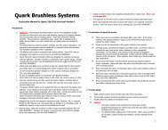
LRCK50% of V DDt BCH t BCL t LBBCK50% of V DDt BCYt BLDATA50% of V DDt DSt DHSYMBOL PARAMETER MIN UNITSt BCY BCK Pulse Cycle Time 70 nst BCL BCK High Level Time 30 nst BCH BCK Low Level Time 30 nst BL BCK Rising Edge to LRCK Edge 10 nst LB LRCK Falling Edge to BCK Rising Edge 10 nst DS DATA Set Up Time 10 nst DH DATA Hold Time 10 ns--- LRCK Clock Duty 50% ± 2-<strong>Bit</strong> ClockFIGURE 5. Audio Interface Timing.CSMCMDIW/R A6 A5 A4 A3 A2 A1A0 D7 D6 D5 D4 D3 D2 D1 D0MDOhigh impedance D7 D6 D5 D4 D3 D2 D1 D0When Read mode is instructedNOTE: B15 is used for the selection of Write or Read. Setting W/R = 0 indicates a Write, while W/R = 1 indicates a Read.B14 to B8 are used for register address.B7 to B0 are used for register data.FIGURE 6. Serial Control Format.EXTERNAL DIGITAL FILTERINTERFACE AND TIMINGThe <strong>PCM1738</strong> supports an external digital-filter interfacecomprised of a 4-wire synchronous serial port that allowsthe use of an external digital filter. External filters includethe DF1704 and DF1706 from Texas Instruments, thePacific Microsonics PMD200, or a programmable digitalsignal processor.The 4-wire interface includes WCK as the word clock, BCK asthe bit clock, DATAL as the L-channel data, and DATAR asthe R-channel data. The external digital-filter interface is selectedusing the DFTH bit of Control Register 20, whichfunctions to bypass the internal digital-filter portion of the<strong>PCM1738</strong>. The 4-wire serial port is assigned to WDCK (pin 4),BCK (pin 6), DATAL (pin 5), and DATAR (pin 15).DSD (DIRECT STREAM DIGITAL) FORMATINTERFACE AND TIMINGThe <strong>PCM1738</strong> supports a DSD format interface operationthat includes out-of-band noise filtering using an internalAnalog FIR filter. For DSD operation, pin 7 is redefined asBCK, which operates at 64 x 44.1kHz; pin 5 is redefined asDATAL (left-channel audio data), and pin 15 becomesDATAR (right-channel audio data). Pins 4 and 6 must beforced LOW in DSD mode. This configuration allows fordirect interface to a DSD decoder for SACD applications.Detailed information for the DSD mode is provided in theDSD Mode Operation section of this data sheet.14<strong>PCM1738</strong>SBAS174A