Multistage centrifugal extractor operating principle - Rousselet Robatel
Multistage centrifugal extractor operating principle - Rousselet Robatel
Multistage centrifugal extractor operating principle - Rousselet Robatel

You also want an ePaper? Increase the reach of your titles
YUMPU automatically turns print PDFs into web optimized ePapers that Google loves.
703 West Housatonic Street – Ste L15<br />
Pittsfield, Massachusetts 01201-6616<br />
manufacturing centrifuges and <strong>centrifugal</strong> extraction equipment<br />
ROUSSELET ROBATEL MODEL LX MULTISTAGE CENTRIFUGAL EXTRACTOR<br />
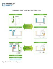
OPERATING PRINCIPLE<br />
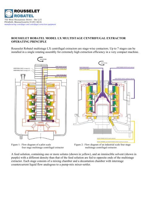
<strong>Rousselet</strong> <strong>Robatel</strong> multistage LX <strong>centrifugal</strong> <strong>extractor</strong>s are stage-wise contactors. Up to 7 stages can be<br />
installed in a single rotating assembly for extremely high extraction efficiency in a very compact machine.<br />
Figure 1: Flow diagram of a pilot scale Figure 2: Flow diagram of an industrial scale four stage<br />
four stage multistage <strong>centrifugal</strong> <strong>extractor</strong> multistage <strong>centrifugal</strong> <strong>extractor</strong>.<br />
A feed solution, containing one or more solutes (shown in yellow), and an immiscible solvent (shown in<br />
purple) with a different density than that of the feed solution are fed to opposite ends of the multistage<br />
<strong>extractor</strong>. Each stage consists of a mixing chamber and a decantation chamber with interstage<br />
countercurrent liquid flow analogous to a pump-mix mixer-settler.
703 West Housatonic Street – Ste L15<br />
Pittsfield, Massachusetts 01201-6616<br />
manufacturing centrifuges and <strong>centrifugal</strong> extraction equipment<br />
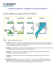
DESCRIPTION OF A MECHANICAL STAGE<br />
Each stage of the LX <strong>extractor</strong> includes:<br />
• a mixing chamber where the two liquids are mixed by means of a stationary agitation disc<br />
mounted on the central drum. The high relative speed between the stationary agitation disc and the<br />
rotating walls of the mixing chamber create an extremely fine dispersion. The agitation disc and<br />
the mixing chamber's inlet and outlet channels form a pump which draws the two phases from the<br />
adjacent stages and also transfers the dispersion to the settling chamber.<br />
• a settling chamber in which the liquids are separated by the <strong>centrifugal</strong> force generated by the<br />
rotating bowl. The heavier liquid (shown in black on Figure 3) occupies the outer portion of the<br />
bowl. The light liquid (shown in gray on Figure 3) occupies the inner portion of the bowl.<br />
Figure 3: Cutaway diagram of a single extraction stage in a multistage <strong>extractor</strong><br />
The position of the liquid / liquid interphase is regulated using a fixed diameter light phase weir and<br />
interchangeable heavy phase weirs of different diameters to accommodate a wide range of density ratios.<br />
Due to the large interfacial area created by the intense mixing, and thanks to the efficient <strong>centrifugal</strong> phase<br />
separation, the extraction efficiency is very high. Each mechanical stage nearly corresponds to a<br />
theoretical stage.<br />
The liquids are discharged from the LX <strong>extractor</strong>s by gravity or by centripetal turbines.
703 West Housatonic Street – Ste L15<br />
Pittsfield, Massachusetts 01201-6616<br />
manufacturing centrifuges and <strong>centrifugal</strong> extraction equipment<br />
MULTISTAGE EXTRACTOR MULTIPLE INLET CONFIGURATIONS<br />
<strong>Rousselet</strong> <strong>Robatel</strong> pilot scale multistage <strong>centrifugal</strong> <strong>extractor</strong>s are equipped with intermediate inlets. They<br />
may therefore be operated as a 1, 2, 3, or 4-stage <strong>extractor</strong> [as examples] to rapidly assess the<br />
improvement in extraction efficiency as a function of the number of stages.<br />
The multiple inlets accommodate a wide variety of flow configurations and extraction processes since a<br />
third liquid that is miscible with one of the two liquid phases in the <strong>extractor</strong> may be fed to stage #2 or<br />
stage #3. This is useful to change pH or ionic strength along the extraction profile or to scrub (wash) the<br />
extract prior to its discharge from the <strong>extractor</strong> (refer to Figure 4 below).<br />
The intermediate inlets can also be used for a fractional extraction whereby the feed solution is introduced<br />
in Stages #2 or #3, with the two solvents being introduced at Stages #1 and #4.<br />
Figure 4: Flow configurations of a pilot scale four stage multistage <strong>centrifugal</strong> <strong>extractor</strong><br />
Flow Diagram A: Illustrates normal operation as a 4-stage countercurrent <strong>extractor</strong>.<br />
Flow Diagram B: Illustrates operation as a 2-stage countercurrent <strong>extractor</strong> by introducing the light phase<br />
into Stage #3. Note that if the light phase were introduced into Stage #2, three countercurrent extraction<br />
stages would be obtained.<br />
Flow Diagram C: Illustrates contact between two miscible heavy phases and one light phase; for example<br />
three extraction stages plus one scrubbing stage (or other combinations).
703 West Housatonic Street – Ste L15<br />
Pittsfield, Massachusetts 01201-6616<br />
manufacturing centrifuges and <strong>centrifugal</strong> extraction equipment<br />
Flow Diagram D: Illustrates contact between one heavy phase and two miscible light phases; for example<br />
three extraction stages plus one stage of heavy phase washing with a diluent (or other combinations).<br />
PILOT SCALE TESTING<br />
For any <strong>centrifugal</strong> <strong>extractor</strong>, the maximum throughputs and extraction efficiencies can only be<br />
determined by testing the technology on a laboratory and pilot scale. The performance parameters of a<br />
multistage <strong>centrifugal</strong> <strong>extractor</strong> will vary depending on the solvents used, viscosity, temperature, density<br />
ratio, surface tension, and phase flow rate ratio.<br />
Specifically, for a <strong>centrifugal</strong> <strong>extractor</strong>, G-force and the mixing energy are important factors to consider<br />
during testing. As shown in the table below, increased rotational speed provides a higher driving force for<br />
separation. However, as rotational speed increases, this will also increase the mixing energy imparted to<br />
the liquid / liquid system.<br />
Therefore, the maximum rotational speed may not yield the best results. The vigorous mixing at the<br />
higher speed may create a dispersion that is more difficult to separate. Typically, there is a “bandwidth”<br />
of rotational speeds that balances the right amount of mixing with adequate G-force for effective<br />
separation. By testing at several different rotational speeds on a pilot scale, this bandwidth can be quickly<br />
evaluated.<br />
G-FORCE AT BOWL WALL<br />
2000<br />
1800<br />
1600<br />
1400<br />
1200<br />
1000<br />
800<br />
600<br />
400<br />
200<br />
G-FORCE AT BOWL WALL VS. ROTATIONAL SPEED FOR ROUSSELET<br />
ROBATEL MULTISTAGE CENTRIFUGAL EXTRACTORS<br />
LX 570<br />
LX 520<br />
0<br />
0 200 400 600 800 1000 1200 1400 1600 1800 2000 2200 2400 2600 2800 3000 3200 3400 3600 3800<br />
ROTATIONAL SPEED (RPM)<br />
LX 360<br />
LX 320<br />
Figure 5: Rotational speed vs. G-force for <strong>Rousselet</strong> <strong>Robatel</strong> multistage <strong>centrifugal</strong> <strong>extractor</strong>s<br />
LX 200<br />
LX 120