OPERATING ANd INSTALLATION INSTRUCTIONS - Stiebel Eltron
OPERATING ANd INSTALLATION INSTRUCTIONS - Stiebel Eltron
OPERATING ANd INSTALLATION INSTRUCTIONS - Stiebel Eltron

You also want an ePaper? Increase the reach of your titles
YUMPU automatically turns print PDFs into web optimized ePapers that Google loves.
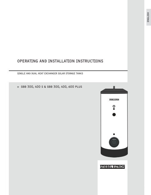
ENGLISH<strong>OPERATING</strong> AND <strong>INSTALLATION</strong> <strong>INSTRUCTIONS</strong>SINGLE AND DUAL HEAT EXCHANGER SOLAR STORAGE TANKS›› SBB 300, 400 S & SBB 300, 400, 600 PLUSWWW.STIEBEL-ELTRON-USA.COM SBB S & SBB PLUS SOLAR STORAGE TANKS | 1
1. CONTENTSSECTIONPAGE1. Contents __________________________________________________________ 22. Safety Instructions _______________________________________________ 33. Operation and Service ___________________________________________ 43.1 Start-up __________________________________________________________________ 44. Maintenance and Cleaning ______________________________________ 44.1 Pressure Relief Valve ___________________________________________________ 44.2 Decalcification ___________________________________________________________ 44.3 Sacrificial Anode – Inspection / Replacement _____________________ 45. Failures – Cause – Correction ___________________________________ 56. Technical Specifications __________________________________________ 56.1 Technical Data & Specifications ______________________________________ 66.2 Dimensions ______________________________________________________________ 77. Installation Instructions - General ______________________________ 87.1 Set-up_____________________________________________________________________ 87.1.1 Brief Description of the Appliance - Applications ________________ 87.1.2 Connections ______________________________________________________________ 87.2 Delivery Configuration _________________________________________________ 87.3 Tasks to be performed by Installer __________________________________ 87.4 Regulations and Standards ___________________________________________ 88. Set-up and Installation __________________________________________ 98.1 Set-up_____________________________________________________________________ 98.2 Connections ______________________________________________________________ 98.3 Heater Installation ______________________________________________________ 98.4 Hot Water Installation _________________________________________________ 98.4.1 Local Site Conditions ___________________________________________________ 98.4.2 Required Pipe Combinations _________________________________________ 98.4.3 Cold Water Supply Safety Components _____________________________ 98.4.4 Pressure Regulator Settings __________________________________________ 98.4.5 Before Filling ____________________________________________________________ 98.4.6 Drainage and Re-circulation _________________________________________ 98.5 Hot Water Temperature Probe ______________________________________128.6 Solar Storage Tank – Temperature Probe _________________________128.7 Connection to the Solar Unit ________________________________________128.8 Sacrificial Anode _______________________________________________________129. Temperature & Pressure Relief Valve Assembly ______________1310. Warranty _________________________________________________________152 | SBB S & SBB PLUS SOLAR STORAGE TANKS WWW.STIEBEL-ELTRON-USA.COM
2. SAFETY <strong>INSTRUCTIONS</strong>ENGLISHGeneral InformationRead this entire manual. Failure to follow all the guides,instructions and rules could cause personal injury or propertydamage. Improper installation, adjustment, alteration, service anduse of this unit can result in serious injury.This unit must be installed by a professional installer. Theinstallation must comply with all national, state and local plumbingand electric codes. Proper installation is the responsibility of theinstaller. Failure to comply with the installation and operatinginstructions or improper use voids the warranty.Save these instructions for future reference. Installer should leavethese instructions with the consumer.Service of the unit must be performed by a qualified service agency.Never set the solar loop pressure greater than potable (domestic)water supply pressure. If the potable water pressure is too low, abooster pump may be needed to assure that it exceeds the requiredsolar loop pressure.If you have any questions regarding the installation, use or operationof this water heater, or if you need any additional installationmanuals, please call our technical service line at 800-582-8423(USA and Canada only). If you are calling from outside the USA orCanada, please call USA 413-247-3380 and we will refer you to aqualified <strong>Stiebel</strong> <strong>Eltron</strong> service representative in your area.THIS IS THE SAFETY ALERT SYMBOL. IT IS USED TO ALERT YOUTO POTENTIAL PERSONAL INJURY HAZARD. OBEYALLSAFETYMESSAGES THAT FOLLOW THIS SYMBOL TO AVOID POSSIBLE INJURY ORDEATH.Safety InstructionsWARNING: NEVER INSTALL ANY VALVES OR SHUTOFF DEVICES INTHE PIPING BETWEEN THE COLLECTORS AND THE SAFETY VALVE.THE SAFETY VALVE IS ACTUATED AT 87 PSI PRESSURE.DANGER: WATER TEMPERATURES OVER 125°F CAN CAUSE SEVEREBURNS INSTANTLY OR DEATH FROM SCALDING. A HOT WATERSCALDING POTENTIAL EXISTS IF THE THERMOSTAT ON THE UNIT IS SETTOO HIGH. HOUSEHOLDS WITH SMALL CHILDREN, DISABLED OR ELDERLYPERSONS MAY REQUIRE THAT THE THERMOSTAT BE SET AT 120°F ORLOWER TO PREVENT POSSIBLE INJURY FROM HOT WATER.DANGER: SETTING THE MAXIMUM TANK TEMPERATURE HIGHERTHAN 140°F AT THE CONTROL UNIT IS PERMISSIBLE ONLY INCONJUNCTION WITH A THERMOSTATICALLY-CONTROLLED DHW MIXINGVALVE. OTHERWISE THERE CAN BE A RISK OF SCALDING AT THE DRAWOFFPOINT.CAUTION: ALL SENSOR WIRING SHOULD BE RATED FOR EXPECTEDTEMPERATURES AND MUST BE PROTECTED FROM DEGRADATIONAND ELECTRICAL INTERFERENCE.Solar LoopUse only a mixture of 50% GRAS (food grade) Propylene Glycol andde-ionized water. (Heat Exchanger type SW, AWWA Fluid Class II -see MSDS for handling instructions.)WARNING: FLUID MAY BE DISCHARGED AT HIGH TEMPERATUREAND/OR PRESSURE. THERE CAN BE A RISK OF SCALDING AT THEDISCHARGE POINT.NO OTHER FLUID SHALL BE USED THAT WOULD CHANGE THE ORIGINALCLASSIFICATION OF THIS SYSTEM. UNAUTHORIZED ALTERATIONS TO THISSYSTEM COULD RESULT IN A HAZARDOUS CONDITION.WWW.STIEBEL-ELTRON-USA.COM SBB S & SBB PLUS SOLAR STORAGE TANKS | 3
3. OPERATION AND SERVICE3.1 Start-upThe hydronic back-up boiler (see Figure 5) and solar storagetank (see Figures 4 & 5), constitute a functional unit. Hot water isgenerated throughout the year by the solar collectors (see Figure 4).Supplemental heat is provided by the back-up boiler when there isinsufficient solar energy available (see Figure 5).The entire heater and hot water system must be filled with waterand have adaquate air ventilation. Please refer to the solarcollector’s and the boiler’s installation instructions.4. MAINTENANCE AND CLEANINGRoutine care and maintenance extends the life expectancy andoperating safety of the hot water storage unit. The outer casingshould be cleaned with a slightly damp cloth and commerciallyavailable neutral cleaning agent. This should be done on a regularbasis.4.1 Temperature / Pressure Relief Valve4.3 Replacement of the Sacrificial AnodeDepending on the composition of the tap water, an inspectionof the sacrificial anode (Pos. 1, Figure 1) at timely intervals isrecommended. With heavy wear, an original equipment replacementanode must be installed to protect the inner container fromcorrosion. An inspection should be performed at least once a year.WARNING: THE T&P RELIEF VALVE IS DESIGNED TO RELIEVE BUILTUP PRESSURE IN THE WATER HEATER. FLUID MAY BE DISCHARGEDAT HIGH TEMPERATURE AND/OR PRESSURE. SCALDING HOT WATERINJURIES CAN OCCUR.NOTICE: THE WATER HEATER AND T&P RELIEF VALVE SHOULD BEINSTALLED AND PIPED IN AND TO AN AREA WHERE WATER DISCHARGEAND LEAKING WILL NOT CAUSE PROPERTY DAMAGE.The proper function of the Temperature / Pressure (“T&P”) reliefvalve is required to prevent damage to the hot water storage unit.The T&P valve needs to be open during cold-water addition. Thewater has to flow from the relief line at full stream.4.2 DecalcificationWith hard tap water, a deposit of scale will form on the inside ofthe storage unit. Based on professional experience, it is necessaryto decalcify with commercially available solvents at timely intervals.Follow the manufacturers instructions for solvent use. The hot waterstorage unit needs to be emptied. The inspection cover must beremoved and sediments on the tank bottom must be flushed.4 | SBB S & SBB PLUS SOLAR STORAGE TANKS WWW.STIEBEL-ELTRON-USA.COM
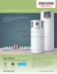
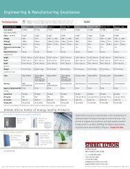
5. FAILURES – CAUSES – CORRECTIONENGLISHFailures Causes CorrectionInadequate water pressureShut-off valve is not completely open.Open Shut-off valve. Clean or exchange pipes.Cold or hot water line is obstructed.Hot water flow inadequateBoiler temperature is set too low.Recommended 176 to 185 °F / 80 to 85 °C.Heat exchanger is calcified.Set boiler to recommended temperature.Clean heat exchanger.Hot water storage tank not being heatedProgram selection at the heater control is notSelect and set program per instructions.properly selected.Outlet quantity inadequate Aerator at the extraction point blocked. Unscrew aerator and clean.Hot water supply exhausted too quicklyFlow rate too high. Recommended 2.6-3.9 gal./min.or 9.8-14.8 l/min.Restrict spigot valve rate.6. TECHNICAL SPECIFICATIONS1Components of the SBB S / SBB Plus1. Sacrifical anode indicator2. Glass lined steel tank3. Thermometer well4. Immersion sleeve for boiler temperature probe5. Spare port6. Immersion sleeve for solar temperature probe7. Inspection port8. Expanded polystyrene-thermal insulation9. Cold water inlet (SBB 300 & 400 S/Plus)10. Solar/main inlet11. Solar/main heat exchanger12. Solar/main return13. Heat exchanger from boiler feed (SBB 300, 400, 600 Plus)14. Upper heat exchanger (SBB 300, 400, 600 Plus)15. Heat exchanger to boiler return (SBB 300, 400, 600 Plus)16. Warm water outlet / T&P relief valve location17. Cold water inlet (SBB 600 Plus)18. Circulation portWWW.STIEBEL-ELTRON-USA.COM SBB S & SBB PLUS SOLAR STORAGE TANKS | 5
6.1 Technical Data and SpecificationsModel SBB 300 S SBB 400 SItem No. 221219 221222ContentsStorage capacity Gal / l 80.6 / 305 108.6 / 411Volume of heat exchanger, top Gal / l N/A N/AVolume of heat exchanger, bottom Gal / l 2.7 / 10.1 2.9 / 11.3PressureWorking pressure PSI / bar 150 / 10 150 / 10Tested to pressure PSI / bar 217 / 15 217 / 15Max. pressure of boiler loop PSI / bar 150 / 10 150 / 10TemperatureMax. temperature lower loop °F / °C 203 / 95 203 / 95Max. temperature of upper loop °F / °C N/A N/AHeat exchangerSurface area heat exchanger top sq in / m 2 N/A N/ASurface area heat exchanger bottom sq in / m 2 2,325 / 1.5 2,635 / 1.7WeightsTank weight empty lb. / kg 292 / 133 371 / 169Tank weight full lb. / kg 988 / 448 1,304 / 591OtherStandby losses in 24 hours BTU / kWh 6,500 / 1.9 7,500 / 2.2Cold/hot water connectionfor 1” copper pipe with adapters, provided with unitModel SBB 300 PLUS SBB 400 PLUS SBB 600 PLUSItem no. 187873 187874 187875ContentsStorage capacity Gal / l 80.6 / 305 108.6 / 411 162.9 / 617Volume of heat exchanger, top Gal / l 1.9 / 7.3 2.2 / 8.2 2.5 / 9.6Volume of heat exchanger, bottom Gal / l 2.7 / 10.1 2.9 / 11.3 3.5 / 13.2PressureWorking pressure PSI / bar 150 / 10 150 / 10 150 / 10Tested to pressure PSI / bar 217 / 15 217 / 15 217 / 15Max. pressure of boiler loop PSI / bar 150 / 10 150 / 10 150 / 10TemperatureMax. temperature lower loop °F / °C 203 / 95 203 / 95 203 / 95Max. temperature of upper loop °F / °C 203 / 95 203 / 95 203 / 95Heat exchangerSurface area heat exchanger top sq in / m 2 1705 / 1.1 2,015 / 1.3 2945 / 1.9Surface area heat exchanger bottom sq in / m 2 2325 / 1.5 2,635 / 1.7 3875 / 2.5WeightsTank weight empty lb. / kg 339 / 154 412 / 187 544 / 247Tank weight full lb. / kg 988 / 448 1,362 / 618 1,955 / 887OtherStandby losses in 24 hours BTU / kWh 6,500 / 1.9 7500 / 2.2 10,000 / 2.9Cold/hot water connectionfor 1” copper pipe with adapters, provided with unit6 | SBB S & SBB PLUS SOLAR STORAGE TANKS WWW.STIEBEL-ELTRON-USA.COM
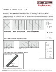
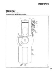
2DimensionsENGLISHType SBB 300 S / Plus SBB 400 S / Plus SBB 600 PlusA Height of unit w/insulation in/mm 66.1/1679 72.7/1848 68.3/1735B Height of unit without insulation in/mm 63.3/1609 70.1/1781 65.7/1670C Height of well for temp. sensor in/mm 46.4/1179 48.7/1238 46.9/1192D Height thermometer in/mm 41.1/1045 43.0/1093 41.5/1055E Height spare port in/mm 40.3/1025 42.4/1078 40.9/1040F Height of well for temp. sensor in/mm 21.9/557 22.0/560 23.4/595G Height inspection flange in/mm 14.4/365 14.4/367 15.9/405H Height cold water feed in/mm 2.9/73 2.6/65 2.0/50I Height solar cold feed in/mm 11.0/280 11.1/282 10.9/277J Height solar hot return in/mm 34.0/865 34.1/867 33.9/862K Height heater hot boiler return in/mm 38.4/975 44.5/1130 42.9/1089L Height circulation port in/mm 52.7/1339 63.0/1600 57.2/1453M Height cold boiler feed in/mm 52.7/1339 63.0/1600 57.2/1453N Overall height in/mm 67.08/1704 73.74/1873 69.29/1760O Width without thermal insulation in/mm 21.65/550 23.62/600 29.52/750P Width with thermal insulation in/mm 27.55/700 29.52/750 36.22/920WWW.STIEBEL-ELTRON-USA.COM SBB S & SBB PLUS SOLAR STORAGE TANKS | 7
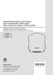
7. <strong>INSTALLATION</strong> <strong>INSTRUCTIONS</strong> FOR THE PROFESSIONAL7.1 GeneralFigure 1 is referenced for explanation of the following text.7.1.1 Brief Description of the Appliance - ApplicationsThe <strong>Stiebel</strong> <strong>Eltron</strong> Vertical Solar Storage tank SBB S / Plus, incombination with <strong>Stiebel</strong> <strong>Eltron</strong>’s Solar Collector is an economicalhot water generator.The <strong>Stiebel</strong> <strong>Eltron</strong> Vertical Solar Storage tank SBB S / Plus, incombination with any hydronic boiler also functions as an efficientindirectly fired water heater.7.4 Regulations and StandardsWARNING: THIS PRODUCT MUST BE INSTALLED ACCORDING TOALL NATIONAL AND LOCAL PLUMBING AND ELECTRICAL CODES. ITMUST BE INSTALLED BY A LICENSED PLUMBER AND ELECTRICIAN.Refer to: all local construction, fire-code and trade controlregulations.3Figure 3: SBB 600 Plus Solar Tank with insulation7.1.2 ConnectionsAll connections (cold and hot) are readily accessible and allow foreasy installation.7.2 Delivery ConfigurationThe hot water storage tank SBB S / Plus is wrapped in plastic and isdelivered on a one-way pallet. The storage tank has foam insulation,a ABS outer casing and ABS cover.Equipment:• Storage unit with two welded steel plain-ended pipe heatexchangers• Hot water corrosion protection with special enamel coating• Maximum operation pressureHot water 150 PSIHeated water 150 PSI• Three immersion sleeves for housing of temperature probe andthermometer• Magnesium Safety Anode• Circulation Socket• Attached Flange inspection cover (SBB models)• PU Foam insulation 2.95 in. (70 mm.) thick• ABS outer casing with zipper in protective pouch• ABS Cover and Flange coverOnly for SBB 600 Plus:• Removable polyurethane-side panels with fastening strap andlocking parts7.3 Tasks to be performed by InstallerAn approved technician should perform the setup, installation andinitial start-up following these instructions.1 Solar tank2 PU side panel3 Fastening strap4 Locking part8 | SBB S & SBB PLUS SOLAR STORAGE TANKS WWW.STIEBEL-ELTRON-USA.COM
8. SET-UP AND <strong>INSTALLATION</strong>ENGLISH8.1 Set-upNOTICE: THE UNIT SHOULD BE LOCATED IN AN AREA WHEREWATER LEAKAGE FROM THE UNIT OR ANY CONNECTIONS WILL NOTRESULT IN DAMAGE TO THE AREA SURROUNDING THE UNIT.DANGER: THE UNIT MUST NOT BE LOCATED NEAR FLAMMABLE LIQUIDSUCH AS GASOLINE, ADHESIVES, SOLVENTS, PAINT THINNERS, BUTANE,LIQUIFIED PROPANE, ETC. AS THE CONTROLS OF THIS APPLIANCE COULDIGNITE VAPORS CAUSING AN EXPLOSION.Inspect the packaging for damage and remove packaging at theinstallation site. Verify presence of six brass thread to sweat fittings.The installation site must be structurally capable of supporting theweight of the tank when filled. The location has to be above freezing.The water drainage pipe must be freeze proof.8.2 ConnectionRefer to Figure 1 and Figure 2.8.3 Heater InstallationThe installation of the hydronic loop is shown in Figures 4 & 5. Thecircuit must include a Temperature / Pressure Relief Valve, and airvent,a check valve, and an expansion tank.8.4 Hot Water Installation8.4.1 Local Site ConditionsPrior to installation check that the local conditions are compatiblewith the appliance design, especially that the maximum workingexcess pressure of 150 PSI (10 bar.) is not exceeded.8.4.2 Required Pipe Combinations8.4.3 Cold Water Supply Safety ComponentsAll safety components must be installed into the cold water supply(Fill & drail valve, Check valve, isolating ball valve & pressureregulator, see Figures 4 & 5). The order of the individual fittings mustbe in accordance to local regulations.8.4.4 Pressure Regulator SettingsThe pressure regulator has to be set to 150 PSI (10 bar). It canonly be installed into the cold water supply. The supply has to bethoroughly inspected prior to installation. Installation of dirt filtersor any other narrowing of the supply line to the pressure relief valveis forbidden.The temperature & pressure relief valve has to be easily accessible.Expansion water generated during the heating has to flow visibly toa drain. The drainage pipe must be large enough to accommodatewater drainage with a fully opened T & P valve. The drainage pipemust be protected from freezing and must not lead outdoors.The pressure regulator (Figures 4 & 5) has to be set so no waterdrips from the T & P valve.Heavy dripping of the T & P valve can be caused by dirt in the valveseat or water pressure. Water pressure needs to re regulated below150 PSI.8.4.5 Before FillingPrior to filling all screws must be tight.8.4.6 Drainage and Re-circulationDrainage of the hot water tank is via the fill & drain valve (Figures 4& 5).A re-circulator can be attached to a separate socket across thethermometer. Drill the outer casing with a hole saw Ø 50 wheremarked and remove insulation from the socket in that area.For energy conservation, use of a circulator is not recommended.A steel or a copper pipe with insulation can be used for the hotwater connectors. Copper pipe with insulation is especially suitabledue to its low heat loss.Required combinations:Cold water pipelineCopper pipeHot water pipelineCopper pipeSteel pipePlastic pipeSteel or copper pipeSteel or copper pipeWWW.STIEBEL-ELTRON-USA.COM SBB S & SBB PLUS SOLAR STORAGE TANKS | 9
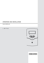
4LEGENDTBC 1 = ball valve withintegrated check &thermometer wellBC 1checkvalveactiveTwo-wayflowactivevalveclosedS Temperature Sensor(RTD)T ThermometerP PressuregaugePipe FittingsCoil-in-tankHeat ExchangerMVSSFlexible Stainless Steel Tube with3/4" BSPP thread union fittingsand manual ventBall valvePump(3-speed)PTFill & DrainValvePressureRel. ValveAV AutomaticVentFlow MeterDisconnectValveCheck ValveDisconnectValveExpansionTankAir FillValveMVSSMVSSSolar CollectorsPumpStationPressure Rel.ValvePressureGauge &ValvePFill &DrainValveBC 1T/S4Pump(3-speed)Throttle andisolationvalveFill &DrainValveFlow MeterMVMVS1SSTBC 11" twinnipples (2)Fill &DrainValveTCS (tank connectionset) - 2 pcs.AVPurg-O-Mat (auto-vent andanti-steaming valve)PT1" union fitting (STAK)S3SBB SSolarStorageTankS2overflowcontainer1" unionfitting(STAK)mixingvalvedomestic watersupplypressureregulatorFigure 4: Installation / system diagram for SBB S solar storage tank without hydronic back-up10 | SBB S & SBB PLUS SOLAR STORAGE TANKS WWW.STIEBEL-ELTRON-USA.COM
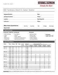
5LEGENDTBC 1 = ball valve withintegrated check &thermometer wellBC 1checkvalveactiveTwo-wayflowactivevalveclosedS Temperature Sensor(RTD)T ThermometerP PressuregaugePipe FittingsCoil-in-tankHeat ExchangerMVSSFlexible Stainless Steel Tube with3/4" BSPP thread union fittingsand manual ventENGLISHBall valvePump(3-speed)PTFill & DrainValveMVSSMVMVSSSSMVS1AV1" union fitting (STAK)PTto DHW pipingoverflowcontainer1" unionfitting(STAK)domestic watersupplyPressureRel. ValveAV AutomaticVentFlow MeterDisconnectValveCheck ValveSolar CollectorsPumpStationPressure Rel.ValvePressureGauge &ValvePDisconnectValveExpansionTankT/S4Air FillValveFill &DrainValveBC 1Pump(3-speed)Throttle andisolationvalveFill &DrainValveFlow MeterPurg-O-Mat(auto-ventandanti-steamingvalve)TBC 11" twinnipples (2)Fill &DrainValveTCS (tank connectionset) - 2 pcs.to heating zonesAfterheat LoopS3SBB PlusSolarStorageTankS2PumpPumpEXmixingvalveAfterheatingSystem(boiler)mixingvalvePpressureregulatorFigure 5: Installation / system diagram for SBB Plus solar storage tank with hydronic back-upWWW.STIEBEL-ELTRON-USA.COM SBB S & SBB PLUS SOLAR STORAGE TANKS | 11
8.5 Hot water temperature probeThe hot water temperature probe is to be installed into the upperimmersions sleeve (Pos. 3, Figure 1).8.6 Solar Storage Tank – Temperature ProbeThe solar storage tank temperature probe to lower immersion sleeveof the hot water storage tank (Pos. 6, Figure 1). The temperatureprobe must be completely inserted into the probe sleeve.pressure ring, (see Figure 7).• Push in the open pipe end of the indicator element until deadstop.• Attach the sticker “Note Signal Anode” to a highly visible spot onthe insulation.NOTICE: WHEN THE STORAGE TANK IS NOT OPERATED WITH A SIGNALDISPLAY, THE RED PLUG MUST REMAIN IN THE ANODE.Function – Sacrificial indicator6Figure 5: Temperature probe assembly• After consumption of the anode, humidity escapes through thehollow anode core to the signal cartridge and causes a colorchange there (see Figure 7)• When the cartridge turns red contact the installer so he can checkthe anode and if needed replace it.Routine maintenance improves operating safety and lifeexpectancy of the SBB S and SBB Plus solar hot waterstorage tanks.7Figure 6: Sacrificial anode indicator8.7 Connection to the Solar UnitThe installation of the solar loop is shown in Figures 4 & 5. The solarloop must include temp/pressure relief, an air-vent, a check valveand an expansion tank. Refer to the separate operation and installationinstructions for the SOL 25 Plus flat plate solar collector.IMPORTANT NOTICE: TEST OPERATION AFTER <strong>INSTALLATION</strong>. START UPMUST FOLLOW THE APPROVAL OF THE INSTALLER (REFER TO SECTION 3.OPERATION AND SERVICE).8.8 Sacrificial anode (spare part)If a sacrificial anode is installed into the SBB S or SBB Plus storagetank, the following must be observed:Installation – sacrificial anode• Pull out the red shut-off plug while simultaneously depressing the12 | SBB S & SBB PLUS SOLAR STORAGE TANKS WWW.STIEBEL-ELTRON-USA.COM
9. TEMPERATURE & PRESSURE RELIEF VALVE ASSEMBLY8T&P Relief ValveAutomatic-ResettingTemperature and PressureRelief Valve150 psi 210 °FWatts #100XL-83/4” NPTSE# S28640ENGLISH3/4” NPTFSE# S342923/4” copper to DomesticHot Water (DHW)3/4” copper2” of 3/4” copperSE# S258185Figure 8: Exploded view of T&P relief valve assembly including part numbersWWW.STIEBEL-ELTRON-USA.COM SBB S & SBB PLUS SOLAR STORAGE TANKS | 13
9Mounted to top of SBB tankT&P Relief ValveAutomatic-ResettingTemperature and PressureRelief Valve150 psi 210 °FWatts #100XL-83/4˝ NPTSE# S28640Pressure relief safety vent pipe (3/4˝ NPTF)SE# S342923/4˝ copper to Domestic Hot Water (DHW)2˝ of 3/4˝ copperSE# S258185Figure 9: Assembled view of T&P relief valve assembly including part numbersComplete assembly on SBB tank.14 | SBB S & SBB PLUS SOLAR STORAGE TANKS WWW.STIEBEL-ELTRON-USA.COM
10. WARRANTYENGLISHSubject to the terms and conditions set forth in this limitedlifetime warranty, <strong>Stiebel</strong> <strong>Eltron</strong>, Inc. (the “Manufacturer”)hereby warrants to the original purchaser (the “Owner”)that each storage tank (the “Tank”) shall be free fromdefects in the Manufacturer’s materials or workmanshipfor a period of:1. (Lifetime) for tank and heat exchanger2. (10 Year) for part(s) not referenced above3. (Excluded) sacrifial anodeAs Owner’s sole and exclusive remedy for the abovewarranty, Manufacturer shall, at the Manufacturer’sdiscretion, either factory repair or replace the defectiveTank with a replacement unit or part(s) with comparableoperating features. Manufacturer’s maximum liabilityunder all circumstances shall be limited to the Owner’spurchase price for the Tank.This limited warranty shall be the exclusive warrantymade by the Manufacturer and is made in lieu of all otherwarranties, express or implied, whether written or oral,including, but not limited to warranties of merchantabilityand fitness for a particular purpose. Manufacturer shallnot be liable for incidental, consequential or contingentdamages or expenses arising directly or indirectly fromany defect in the Tank or the use of the Tank. Manufacturershall not be liable for any water damage or other damageto property of Owner arising, directly or indirectly,from any defect in the Tank or the use of the Tank.Manufacturer alone is authorized to make all warrantieson Manufacturer’s behalf and no statement, warranty orguarantee made by any other party shall be binding onManufacturer.Manufacturer shall not be liable for any damagewhatsoever relating to or caused by:1. any misuse or neglect of the Tank, any accident tothe Tank, any alteration of the Tank, or any otherunintended use;2. acts of God and circumstances over whichManufacturer has no control;3. installation of the Tank other than as directed byManufacturer and other than in accordance withapplicable building codes;LIMITED LIFETIME WARRANTY4. improper installation and/or improper materialsused by any installer and not relating to defects inparts or workmanship of Manufacturer;5. failure to maintain the Tank or to operate the Tank inaccordance with the Manufacturer’s specifications;6. failed components not originally installed by theManufactuer as a part of the unit at the time of sale;7. exposure to freezing conditions;8. exposure to harmful chemicals, corrosive water,contaminated water, caustic fluids, or liquidsharmful to steel tubing, including improperlyapplied or maintained heat transfer fluids.9. utilizing the tank as an open loop heat exchanger,e.g., do not use in drainback systems or continuallypass fresh potable water through the units internalheat exchanger.Should owner wish to return the Tank to manufacturerfor repair or replacement under this warranty, Ownermust first secure written authorization from Manufacturer.Owner shall demonstrate proof of purchase, including apurchase date, and shall be responsible for all removaland transportation costs. If Owner cannot demonstrate apurchase date this warranty shall be limited to the periodbeginning from the date of manufacture stamped on theTank. Manufacturer reserves the right to deny warrantycoverage upon Manufacturer’s examination of the Tank.This warranty is restricted to the Owner and cannot beassigned.Some States and Provinces do not allow the exclusionor limitation of certain warranties. In such cases, thelimitations set forth herein may not apply to the Owner. Insuch cases this warranty shall be limited to the shortestperiod and lowest damage amounts allowed by law. Thiswarranty gives you specific legal rights and you may alsohave other rights which vary from State to State or Provinceto Province.Owner shall be responsible for all labor and other chargesincurred in the removal or repair of the Tank in the field.Please also note that the Tank must be installed in such amanner that if any leak does occur, the flow of water fromany leak will not damage the area in which it is installed.This Warranty is valid for U.S.A. & Canada only. Warrantiesmay vary by country. Please consult your local <strong>Stiebel</strong> <strong>Eltron</strong>Representative for the Warranty for your country.17 West StreetWest Hatfield, MA 01088TOLL FREE 800.582.8423PHONE 413.247.3380FAX 413.247.3369info@stiebel-eltron-usa.comwww.stiebel-eltron-usa.comWWW.STIEBEL-ELTRON-USA.COM SBB S & SBB PLUS SOLAR STORAGE TANKS | 15