Owners Manual - Boston Whaler
Owners Manual - Boston Whaler
Owners Manual - Boston Whaler
- No tags were found...

Create successful ePaper yourself
Turn your PDF publications into a flip-book with our unique Google optimized e-Paper software.
R370 Outrage“The mission of <strong>Boston</strong> <strong>Whaler</strong> ®is to provide consumers with thesafest, highest quality, most durableboats in the world”370 Outragei
RT H E U N S I N K A B L E L E G E N D TMRWelcome to the <strong>Boston</strong> <strong>Whaler</strong> family! Congratulations on your purchase of a <strong>Boston</strong> <strong>Whaler</strong> boat.For over 50 years now, <strong>Boston</strong> <strong>Whaler</strong> has been represented by a select group of the best dealers in theboating industry. <strong>Boston</strong> <strong>Whaler</strong> depends on this extremely qualified network of dealers toprovide you, our customer, with a truly exceptional boating experience.Should you have any questions or concerns regarding your boat, please don’t hesitate to contact yourselling dealer. They will be more than happy to provide you with all the information andassistance that you require.Information and assistance is also available at our corporate website, www.bostonwhaler.com. On ourwebsite you will find information on our entire lineup of Unsinkable Legends, as well as a collectionof customer resources including parts diagrams, maintenance tips and frequently asked questions. Inaddition, you can sign up to receive future issues of <strong>Boston</strong> <strong>Whaler</strong>’s lifestyle magazine, <strong>Whaler</strong>.Since <strong>Boston</strong> <strong>Whaler</strong>’s inception in 1958, we have been committed to providing customers with thesafest, highest quality, most durable boats in the world. I am confident that you, as a <strong>Whaler</strong> owner, willalso appreciate the quality and pride that is built into every <strong>Boston</strong> <strong>Whaler</strong> boat.From all of us here at <strong>Whaler</strong>, thank you for purchasing one of our boats. May itbring you many years of boating enjoyment.1958, The legend is bornas company founder Dick Fisherdemonstrates a <strong>Boston</strong> <strong>Whaler</strong>’stotal unsinkability.370 Outrageiii
RHISTORYIn 1958, company founder Richard T. Fisherintroduced the first <strong>Boston</strong> <strong>Whaler</strong> ® boat inBraintree, Massachussetts. It featured two significantinnovations: first, its twin sponson hull designproduced superior stability and a remarkably dry ride;second, its unique foam core construction made theboat not only durable, but unsinkable as well.Fisher took every opportunity to illustrate the uniquecharacteristics of the <strong>Boston</strong> <strong>Whaler</strong> ® . His mostfamous demonstration was captured in 1961, byLife Magazine. The series of photographs showedthe boat underway, the boat being sawed in half andultimately Fisher motoring away in the remaininghalf of the boat. And through the years many otherdemonstrations have proved the toughness anddurability of the <strong>Boston</strong> <strong>Whaler</strong> hull. And thoughyou may never cut your boat in half, this only goesto show one thing, people whose livelihood and livesdepend on boats consistently choose <strong>Boston</strong> <strong>Whaler</strong> ®because of their seaworthiness, dependablility andthe inherent safety of a hull that won’t sink even ifseverely damaged.<strong>Boston</strong> <strong>Whaler</strong>s are built to last. For over 50 years<strong>Boston</strong> <strong>Whaler</strong> ® has strived to make each modelbetter, providing you with a safe and fun boatingexperience. That is the reason we offer a 10 yearlimited transferable warranty. It is also an excellentreason why you can trust the safety of your familyand friends to a <strong>Boston</strong> <strong>Whaler</strong> ® .Richard T. Fisher was posthumouslyinducted into the National Marine Manufacturer’sAssociation (NMMA) Hall of Fame on September26, 1996 for accomplishments made in marineengineering and construction.1958, The legend is bornas company founder Dick Fisherdemonstrates a <strong>Boston</strong> <strong>Whaler</strong>’stotal unsinkability.PLEASE KEEP THIS OWNER’S MANUAL PACKET IN A SECURE PLACE, AND BE SURE TO HANDIT OVER TO THE NEW OWNER IF YOU SELL THE BOAT.iv370 Outrage
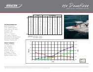
RTABLE of CONTENTSWelcome Letter ..........................................iiiHistory ......................................................ivPreface ......................................................ix<strong>Boston</strong> <strong>Whaler</strong> Limited Warranty ................. x<strong>Boston</strong> <strong>Whaler</strong> Limited WarrantyAustralia .............................................. xiiiPrivacy Statement ................................... xviiIntroduction ........................................... xviiiOwner’s manual ................................. xviiiYour responsibilites ............................. xviiiSource of Information ......................... xviiiWarranties ......................................... xviiiContact Phone Numbers andInternet Addresses........................... xviiiSection 1 • SafetyExplanation of Safety Precautions ............. 1-1Warning Labels ....................................... 1-1Safe Boating means ................................. 1-2To Obtain These Skills .......................... 1-2In Addition .......................................... 1-2Safe Boating Checklist ............................. 1-2Before departure ................................. 1-2Trailering (if applicable) ........................ 1-2After Return ........................................ 1-2General Considerations ............................ 1-3Maintain Control ...................................... 1-3Boarding ................................................. 1-3Impaired Operation ................................. 1-3Legally Mandated Equipment(Minimum Required) ............................ 1-5Personal Flotation devices (PFD’s) ......... 1-5Fire Extinquisher (Portable) .................. 1-5Whistle, Horn ...................................... 1-5Visual Distress Signal ........................... 1-5Additional recommended Equipment forSafe Operation .................................... 1-5Carbon Monoxide (CO) ............................ 1-6Carbon Monoxide detectors .................. 1-7Lifesaving Equipment............................... 1-7PFD Requirement ................................ 1-7General Considerations ...................... 1-8Emergency Situations ............................ 1-10Medical Emergency ............................ 1-10Water Rescue .................................... 1-10Returning to the victim .................... 1-10Making contact ............................... 1-10Getting back on board ..................... 1-10Fire ..................................................... 1-10To lessen the danger of fire ................ 1-11Flooding, Swamping and Capsizing ......... 1-11Flooding ........................................... 1-11Swamping ......................................... 1-11Capsizing .......................................... 1-11Collision ................................................ 1-12Propulsion, Control or Steering Failure .... 1-12Grounding ............................................ 1-12Distress Signals ..................................... 1-12Visual distress signals (VDS) ............... 1-12Audible distress signals ...................... 1-13Radio Communication ............................ 1-13Weather ............................................... 1-13Swimming, Diving & Water Skiing ........... 1-14Swimming ......................................... 1-14Diving ............................................... 1-14Water Skiing ..................................... 1-15Water Skiing Signals .......................... 1-15Emergency Engine Stop Switch .............. 1-17Float Plan ............................................. 1-17Chart Your Course ................................. 1-17Environmental Considerations ................ 1-18Fuel & Oil Spillage ............................. 1-18Excessive Noise ................................. 1-18Wake/Wash ....................................... 1-18Homeland Security Restrictions .............. 1-19America’s Waterway Watch .................... 1-19Warning Label Locations ........................ 1-19Key To Symbols Used on Controls& Prints ............................................ 1-24Section 2 • General InformationConstruction Standard ............................. 2-1Our Hull .................................................. 2-1Hull Identification Number .................... 2-1Servicing Your <strong>Boston</strong> <strong>Whaler</strong> ................... 2-1Manufacturer’s Certification ...................... 2-1Certification design Category ................ 2-3Power Capacity .................................... 2-3Specifications & Dimensions ..................... 2-4Passenger Areas ...................................... 2-5Recommended Passenger Locations ......... 2-6370 Outragev
RTABLE of CONTENTSLocation Of Thru-Hull Fittings ................... 2-7General Layout, Exterior .......................... 2-9General Layout, Control Station .............. 2-10General Layout, Port Aft Cockpit ............. 2-11General Layout, Starboard Aft Cockpit ..... 2-12General Layout, Prep Station .................. 2-13General Layout, Summer Kitchen (Option) 2-14General Lauout, Cabin ........................... 2-15General Layout, Hardtop ........................ 2-17General Layout, Console Lounge............. 2-18Seating ................................................. 2-19Notable Options .................................... 2-20Switch Panels ........................................ 2-22Gear Shift & Throttle Control .................. 2-24Digital Throttle/Shift (DTS ® ) ............... 2-24DTS Control Pad ................................ 2-24Shadow Mode Technology .................. 2-25Auto Sync® ....................................... 2-25Power trim Operation ............................ 2-25Power Trim and Trim Tabs ...................... 2-26Trim Guidelines ..................................... 2-26Smartcraft TM VesselView ......................... 2-27System Calibration(For First Time Use) ........................ 2-27Upper Control Station (Option) ............... 2-28Station Transfer ................................. 2-28Navigation Lighting ................................ 2-30Operating The navigation Lighting ...... 2-30Canvas (Option) .................................... 2-31Installation ........................................ 2-31To Remove Canvas ............................ 2-32Bow Thruster ........................................ 2-33To Operate The Bow Thruster ............. 2-34Towing, Docking and Lifting ................... 2-35Bow Tow Eye (Option) ....................... 2-35Docking ............................................ 2-36Lifting ............................................... 2-36Section 3 • Systems & ComponentsOverview & OperationBilge Pumps ............................................ 3-1Emergency High Water Bilge Pump ........... 3-1Access To The Pumps .......................... 3-2Maintenance ....................................... 3-2Float Switch ........................................ 3-2Fuel & Oil Spillage ............................... 3-2Gray Water Sump ................................ 3-2Maintenance ..................................... 3-3Thru Hull Discharge Hoses ....................... 3-3Access ................................................ 3-3Fuel System ............................................ 3-4Fuel Fill ............................................... 3-4Fuel Tank ............................................ 3-5Fuel Vent ......................................... 3-5Maintenance ..................................... 3-5Static Electricity and the Fuel System ........ 3-5Ethanol-Blended Fuel ............................... 3-6Filling the Tank .................................... 3-6Phase Separation ................................. 3-6Additives ............................................. 3-7Fuel Filters .......................................... 3-7Maintenance ....................................... 3-7Storage ............................................... 3-7Power Steering ........................................ 3-8Filling & Maintenance ........................... 3-8Starting/Stopping the Engines .................. 3-9Starting The Engines ......................... 3-9Warming Up The Engines ................ 3-10Stopping the Engines ...................... 3-10Fresh Water System .............................. 3-11Filling the tank................................ 3-11Freshwater Pump ............................ 3-12Deck Showers................................. 3-12Anchor Locker Washdown ...................... 3-13Cockpit Misting System (Option) ............. 3-13Maintenance ..................................... 3-13Changing The Filter......................... 3-13Dockside Water Inlet ............................. 3-14To Use The System ............................ 3-14Water Heater ........................................ 3-14Maintenance ..................................... 3-15Fresh Water Syatem Maintenance ........... 3-15Raw Water System ................................ 3-16Full-Fill Livewell .............................. 3-16Full-Fill Livewell Operation ............... 3-17Maintenance ................................... 3-17Raw Water Washdown ........................... 3-18Maintenance ..................................... 3-18Head System ........................................ 3-19Environmental Considerations ............. 3-19Vacu-Flush ® Head ............................. 3-19Operation ....................................... 3-19Macerator & Dockside Discharge ......... 3-20Overboard Discharge ......................... 3-21vi370 Outrage
RTABLE of CONTENTSMaintenance ..................................... 3-21Dockside Pump-Out ........................... 3-21Waste System Vent ............................ 3-22Convertable Head .............................. 3-22Air Conditioning .................................... 3-23Windshield Defogging Vents ............... 3-23Operation .......................................... 3-23Air Flow Vent ..................................... 3-24Maintenance ..................................... 3-24Generator ............................................. 3-25Fuel .................................................. 3-25Starting The Generator ...................... 3-27Stopping The Generator ..................... 3-28Maintenance ..................................... 3-28Generator Fuel Filter .......................... 3-28Fuel Filter Maintenance ...................... 3-29Raw Water Strainer Maintenance ........ 3-29Operation In European UnionMember Countries .......................... 3-30Shore Power ......................................... 3-30ELCI (Equipment Leakage CircuitInterrupter) .................................... 3-30Dual Shore Power .............................. 3-31Single Cord Shore Power .................... 3-32Battery Charging ............................... 3-32Shore Power Load Management .......... 3-32Isolation Transformers ....................... 3-33Fire Suppression System ........................ 3-34In The Event Of Discharge ................. 3-34<strong>Manual</strong> Override System .................... 3-35To Operate ..................................... 3-35Dive Door ............................................. 3-36Dive Ladder .......................................... 3-36Fishboxes With Pump Out Discharge ....... 3-37Cockpit Fishbox Freezer Plates (Option) .. 3-37Deck Showers ....................................... 3-38Electric Downrigger Recptacles (Option) .. 3-39Transom Door ....................................... 3-39Swim Ladder ......................................... 3-40Foldaway Aft bench Seat ........................ 3-40Foldaway Trolling Seats (Option) ............ 3-41Stowable Cockpit Table (Option) ............. 3-41To Set Up Table ................................. 3-41Bow Table (Option) ............................... 3-42Electric Grill (Option) ............................. 3-42To Remove The Grease Pan ................ 3-42Automatic Shut-Off ............................ 3-42Ceramic Cook top (Option) ..................... 3-43Cook top Retaining Pins ..................... 3-43Bait Prep Station Refrigerator ................. 3-44Adjustable Helm Seat ............................ 3-45Fold Down Visibility Platform .................. 3-45Radial Outriggers (Option) ..................... 3-46Operation .......................................... 3-46Maintenance ..................................... 3-46Spotlight (Option) ................................. 3-47Programming The Transmitter ............ 3-47Replacing The Batteries ..................... 3-47Hardtop Access ..................................... 3-47Electric Windshield Vent ......................... 3-48Windshield Wiper/Washer ...................... 3-48Electric Sunshade (Option) ..................... 3-48Cabin Shower ....................................... 3-49Shower Curtain ................................. 3-49Vanity ................................................... 3-49Coffee Maker ........................................ 3-50Microwave ............................................ 3-50Cabin Refrigerator ................................. 3-50Cabin Convertable Setee/Bunk ............... 3-51Sky Lights ............................................. 3-51Hanging Locker & Storage ..................... 3-51Telephone Hook UP ............................... 3-51Television ............................................. 3-52To Connect Cable Telvision ................. 3-52Stereo/DVD Player ................................. 3-52Operating Your MP3 Player ..................... 3-53Operating Your MP3 Player UsingThe USB Input ...................................... 3-54Lighting ................................................ 3-54Cabin Lighting ................................... 3-54Cockpit Lighting ................................. 3-55Storage Garage Lights ........................ 3-55Hardtop Lighting ............................... 3-55Blue Aesthetic Lighting .................... 3-55Map Lights ..................................... 3-55Spreader Lights .............................. 3-56Underwater Lights ............................. 3-56Storage Garage ..................................... 3-56Storage Garage Lock ............................. 3-56Rod Holders .......................................... 3-57To Stow Your Fishing Rods ................. 3-57Dive Tank Racks (Option) ....................... 3-57To Stow Your Dive Tanks .................... 3-57Trim Tabs .............................................. 3-58Operation ............................................. 3-58Electrolytic Corrosion & Zinc Anodes ....... 3-58Maintenance ......................................... 3-59Propeller ............................................... 3-59370 Outragevii
RTrimming The Engines ....................... 3-59Changing Propellers ........................... 3-59Anchor Windlass ................................... 3-60Operation ....................................... 3-61Operating From The Helm ............... 3-61Operating From The Bow ................... 3-61Operating The Windlass <strong>Manual</strong>ly ....... 3-62Anchoring ............................................. 3-63Considerations ................................... 3-63Lowering the Anchor ............................. 3-63Setting the Anchor ................................ 3-64Weighing the Anchor ............................. 3-64Section 4 • ElectricalElectrical System ..................................... 4-1DC Electrical System ............................ 4-1Batteries ................................................. 4-1Battery Trays ....................................... 4-1Battery Charger ................................... 4-2Overload Protection ............................. 4-2Maintenance ....................................... 4-2Battery Switches .................................. 4-2Remote Battery Switches ..................... 4-2Automatic Charging Relays ................... 4-2<strong>Manual</strong> Control Override .................... 4-3Bow Thruster Batteries ............................ 4-4Battery Maintenance ............................ 4-412 Volt Accessory receptacle .................... 4-412 Volt Receptacles.............................. 4-6Main DC Breaker Panel ............................ 4-7DC distribution Panel ........................... 4-7Main AC Breaker Panel ............................. 4-8AC Electrical System ............................ 4-8Component Breakers ............................... 4-9Bait Prep Station Breaker Panel .............. 4-10Summer Kitchen Breaker Panel (Option) . 4-10Battery Switch Panel .............................. 4-11Fuse Blocks ........................................... 4-12Ground Fault Interrupter Receptacle (GFI) 4-13Testing ................................................. 4-13Rigging ................................................. 4-13Transducer Mounting Location ................ 4-14Electrical Schematics & Harnesses .......... 4-15Wiring Identification Chart ..................... 4-15Section 5 • Care & MaintenanceRoutine Care & Maintenance .................... 5-1Hull .................................................... 5-1Waxing the Gel Coat Surfaces .................. 5-1Hull Maintenance..................................... 5-2Hull Blistering ......................................... 5-2Prevention .......................................... 5-2Bottom Painting ...................................... 5-2Bottom Painting a Bare Hull .................. 5-3Bottom Painting a Pre-Painted Hull ........ 5-3Rubrail care ............................................ 5-4Cleaning Fiberglass & Non-Skid ................ 5-4Stainless Steel Care ................................. 5-4Aluminum Care ....................................... 5-5Powder Coated Surfaces .......................... 5-5Powder Coating Touch-Up .................... 5-5Canvas Care and Maintenance .................. 5-6Maintaining a Good Appearance ............ 5-6On a Regular Basis ............................ 5-6Cleaning stubborn Stains ...................... 5-7Maintaining Zippers and Hardware ............ 5-7Maintaining Your Vinyl Windows ............... 5-7Cushions................................................. 5-8To Clean Your Cushions ........................ 5-8Cleaning Tempered Glass Windshield ........ 5-9Cleaning Your Instrument Gauges ............ 5-9Corian ® Solid Surface Countertops ............ 5-9Routine Care ....................................... 5-9Minor Cuts And Scratches ..................... 5-9Heat Damage ...................................... 5-9Other Damage..................................... 5-9Refurbishing ........................................... 5-9Maintaining Your Teak ............................. 5-9Flexiteek Flooring .................................. 5-10Misting System ...................................... 5-10Replacing the Filter ............................ 5-10Flushing the System .......................... 5-10Winterizing the System ...................... 5-10Maintaining The Ultraleather Fabric ......... 5-11Long term Storage & Winterization ......... 5-11Engine .............................................. 5-11Fuel System ...................................... 5-12Battery ............................................. 5-12Livewell/Raw Water System ................ 5-12viii370 Outrage
RFresh Water System ........................... 5-12Head System ..................................... 5-13Air handling System ........................... 5-13Sump ................................................ 5-13Electrical System ............................... 5-13Deck ................................................. 5-13Drainage ........................................... 5-13Avoid Loss ........................................ 5-14Cover................................................ 5-14Environment ......................................... 5-14Reinforcement Locations ........................ 5-14Reinforcement Location Diagram ............ 5-15Maintenance Log ................................... 5-16AttachmentsCommissioning ChecklistProduct Registration CardPrefaceThis Owner’s <strong>Manual</strong> has been written to provide specific information about your boat and it should be read carefully.Keep this booklet with the <strong>Manual</strong>s in the Owner’s <strong>Manual</strong> Packet. The Owner’s <strong>Manual</strong> Packet has been compiled tohelp you operate your boat with safety and pleasure. It contains details of the boat, the equipment supplied or fitted, it’ssystems and information on it’s operation and maintenance. Please familiarize yourself with the boat and it’s operationbefore using it. If this is your first boat, or you are changing to a type of boat you are not familiar with, for your owncomfort and safety, please ensure that you obtain handling and operating experience before “assuming command” ofyour boat. Your <strong>Boston</strong> <strong>Whaler</strong> ® dealer or local Yacht Club will be pleased to advise you of marine safety classes andsafe boating classes in your area.INFORMATION IN THIS PUBLICATION IS BASED ON THE LATEST PRODUCT SPECIFICATIONS AVAILABLE AT PRINTING, BOSTON WHALER ® BOATS, INC. RESERVES THE RIGHTTO MAKE CHANGES AT ANY TIME WITHOUT NOTICE, IN THE COLORS, EQUIPMENT, SPECIFICATIONS, MATERIALS AND PRICES OF ALL MODELS, OR TO DISCONTINUE MODELS.SHOULD CHANGES OR MODIFICATIONS TO THE MODELS BE MADE BOSTON WHALER ® IS NOT OBLIGATED TO MAKE SIMILAR CHANGES OR MODIFICATIONS TO MODELS SOLDPRIOR TO THE DATE OF SUCH CHANGES.BOSTON WHALER • A BRUNSWICK COMPANYMRP #2122940Printed in the U.S.A. © <strong>Boston</strong> <strong>Whaler</strong>, Inc. All rights reserved.370 OUTRAGEJUNE, 2013REVISED SEPTEMBER, 2013THE FOLLOWING ARE REGISTERED TRADEMARKS OF THE BRUNSWICK CORPORATION:OUTRAGE, BOSTON WHALER ® .RSpecifi cations and standard equipment are subject to change. <strong>Boston</strong> <strong>Whaler</strong> is not responsible for changes to parts or accessories manufactured by companies other than <strong>Boston</strong> <strong>Whaler</strong>.Active Deck Suspension System, <strong>Boston</strong> <strong>Whaler</strong>, <strong>Whaler</strong>, the <strong>Boston</strong> <strong>Whaler</strong> logo, Conquest, Dauntless, Montauk, and Outrage are registered trademarks of <strong>Boston</strong> <strong>Whaler</strong>, Incorporated.Accutrack, Unibond, The Unsinkable Legend, Ventura, and Whaleboard are trademarks of <strong>Boston</strong> <strong>Whaler</strong>, Incorporated. Mercury and Optimax are registered trademarks of Mercury Marine, andSmartCraft and Verado are trademarks of Mercury Marine. Trademarks of others are the property of their respective owners. All mercury engine information provided by Mercury Marine, June 2007.Information contained within this publication is believed to be correct at the time of printing.370 Outrageix
RBOSTON WHALER LIMITED WARRANTY- AUSTRALIA<strong>Boston</strong> <strong>Whaler</strong>, Inc. of 100 <strong>Whaler</strong> Way, Edgewater, Florida 32141 USA (“<strong>Boston</strong> <strong>Whaler</strong>”) provides thefollowing Limited Warranty to the original retail owner of its 2014 model year boats, if purchased from anauthorized <strong>Boston</strong> <strong>Whaler</strong> Dealer and operated under normal, non-commercial use (“Boat’’), subject to theremedies, exclusions, and limitations set out below.1. Ten-Year Structural Hull Limited Warranty: Any Structural Hull Defect in material or workmanship whichis reported within ten (10) years from the date of sale to the original purchaser will be repaired or replaced at<strong>Boston</strong> <strong>Whaler</strong>’s sole discretion. The “Hull” shall mean the single fiberglass molded shell and integral structuralcomponents. A Structural Hull Defect shall mean a substantial defect in the Boat’s Hull which causes the boat to beunfit or unsafe for general use as a pleasure craft under normal operating conditions2. Three-Year Limited Warranty on Components Manufactured or Installed By <strong>Boston</strong> <strong>Whaler</strong>: <strong>Boston</strong><strong>Whaler</strong> will repair or replace, at its sole discretion, any components manufactured or installed by <strong>Boston</strong> <strong>Whaler</strong>that are defective in factory materials and/or workmanship, which are reported within three years from the date ofsale to the original purchaser, and are not addressed in the specific warranties listed in paragraph 1 or 3 or set out inthe Exclusions paragraph below.3. One-Year Limited Warranty on Upholstered Items, Canvas, Teak, and Powder Coating: <strong>Boston</strong> <strong>Whaler</strong>will repair or replace, at its sole discretion, any upholstered items, canvas, teak, and powder coating manufacturedor installed by <strong>Boston</strong> <strong>Whaler</strong> that are defective in factory materials and/or workmanship and are reported withinone year from the date of sale to the original purchaser.4. Transportation: For warranty claims filed under the following provisions 1)Ten-Year Structural Hull LimitedWarranty, 2) Three Year Limited Warranty for Warranty Servicing of Vessels with Beams equal to or greater than9 feet and 3) One Year Limited Warranty for Warranty Servicing of Vessels not offered with a standard trailer:Reasonable expenses, at <strong>Boston</strong> <strong>Whaler</strong>’s sole discretion, for hauling out, transportation to and from the dealer orother service provider authorized by <strong>Boston</strong> <strong>Whaler</strong> for warranty service.EXCLUSIONSThis limited warranty does not apply to any boat which has been salvaged or declared a total loss or constructivetotal loss for any reason not covered in this limited warranty. This limited warranty also does not apply to thefollowing items:(1) Except where offered above, expenses for hauling out, transportation to and from the dealer or the <strong>Boston</strong><strong>Whaler</strong> factory for warranty service.(2) Equipment or accessories which are not installed by <strong>Boston</strong> <strong>Whaler</strong> or which carry their own individualwarranties, including but not limited to engines, engine components, batteries, propellers, controls, steeringmechanisms, and electronics.(3) Damage, deterioration, discoloration or mold of cushions, cosmetic surface finishes, including discoloration,chalking, cracking, crazing, fading or oxidation of gel coat, stress lines, plated or painted metal and stainlesssteel finishes, plastics or acrylic materials, or anti-fouling bottom paint.(4) Windshield breakage and leakage.(5) Any <strong>Boston</strong> <strong>Whaler</strong> boat initially sold at retail by a party other than an authorized <strong>Boston</strong> <strong>Whaler</strong> dealer.(6) Damage resulting from abuse, misuse, improper rigging and installation by an owner or any other personor entity not being an authorized dealer, accidents, overloading or powering in excess of the recommendedmaximum horsepower.(7) Failure of the owner to use, maintain, or store the boat as specified in the <strong>Boston</strong> <strong>Whaler</strong> owner’s manual; andany other failure to provide reasonable care and maintenance. Normal wear and tear maintenance items areexcluded from warranty coverage including but not limited to filters, bulbs, batteries, bungees, anchor rope,trailer finishes, tires, brakes, bearings and lights.370 Outragexiii
R(1) Any <strong>Boston</strong> <strong>Whaler</strong> boat which has been altered or modified from <strong>Boston</strong> <strong>Whaler</strong> factory specifications,including penetration of the hull by anyone other than <strong>Boston</strong> <strong>Whaler</strong> factory personnel or <strong>Boston</strong> <strong>Whaler</strong>authorized dealer service personnel following factory specified procedures.(2) Use of improper trailer, improperly placed supporting bunks or slings, incorrect bunks placement and improperboat lift or sling.(3) Any <strong>Boston</strong> <strong>Whaler</strong> boat used for commercial, which includes but is not limited to any for-profit uses, or otherrevenue-generating purposes.(4) Any representation or implication relating to speed, range, fuel consumption or estimated performancecharacteristics.(5) Any failure or defect caused by an act of nature resulting in damage, cost, or expense;(6) Any failure or defect arising from a previous repair made by a non-authorized service provider.(7) Any item exceeding the expressed coverage limits specified in any <strong>Boston</strong> <strong>Whaler</strong> Limited Warranty.(8) Any defect or repair requiring redesign of the Boat, except pursuant to the recall provisions of the United StatesFederal Boat Safety Act of 1971 or the recall laws of any other foreign jurisdiction.SOLE REMEDY UNDER THIS LIMITED WARRANTYTHE REMEDY OF REPAIR OR REPLACEMENT OF PARTS OR MATERIALS THAT ARE FOUND TO BEDEFECTIVE IN FACTORY MATERIALS OR WORKMANSHIP COVERED BY THIS LIMITED WARRANTYSHALL CONSTITUTE THE OWNER’S SOLE AND EXCLUSIVE REMEDY AGAINST BOSTON WHALERUNDER THIS LIMITED WARRANTY FOR ANY CLAIMS WHATSOEVER OF ECONOMIC LOSS RESULTINGFROM PRODUCT FAILURE. In keeping with environmental policies and practices, <strong>Boston</strong> <strong>Whaler</strong> reserves the rightto utilize reconditioned, refurbished, repaired or remanufactured products or parts in the warranty repair or replacementprocess. Such products and parts will be comparable in function and performance to an original product or part andwarranted for the remainder of the original warranty period. In no event shall any repair or replacement under thisLimited Warranty exceed the fair market value of the product as of the date of the owner’s claim. Acceptance ofany product returned or any refund provided by <strong>Boston</strong> <strong>Whaler</strong> shall not be deemed an admission that the productis defective. Products that are replaced become the property of <strong>Boston</strong> <strong>Whaler</strong>.OTHER LIMITATIONSEXCEPT AS SET FORTH HEREIN AND EXCEPT FOR THE GUARANTEES AND OTHER RIGHTS ANDREMEDIES THAT A CONSUMER MAY HAVE UNDER A LAW IN RELATION TO WHICH THE BOAT ORITS COMPONENTS RELATES:1. THERE ARE NO OTHER WARRANTIES EITHER EXPRESS OR IMPLIED PROVIDED BY BOSTONWHALER ON THIS BOAT. ALL OTHER WARRANTIES, EXPRESS OR IMPLIED, INCLUDINGIMPLIED WARRANTIES OF FITNESS AND MERCHANTABILITY, ARE EXPRESSLY EXCLUDED.;2. TO THE EXTENT ALLOWED BY LAW, BOSTON WHALER FURTHER DISCLAIMS ANY LIABILITYFOR ECONOMIC LOSS ARISING FROM CLAIMS OF PRODUCT FAILURE, NEGLIGENCE,DEFECTIVE DESIGN, MANUFACTURING DEFECT, FAILURE TO WARN AND/OR INSTRUCT,LACK OF SEAWORTHINESS, AND ANY OTHER THEORY OF LIABILITY NOT EXPRESSLYCOVERED UNDER THE TERMS OF THIS LIMITED WARRANTY;3. ANY IMPLIED WARRANTY OF MERCHANTABILITY OR FITNESS FOR A PARTICULARPURPOSE IS DISCLAIMED; AND.4. TO THE EXTENT ALLOWED BY LAW, NEITHER BOSTON WHALER, NOR THE SELLINGDEALER, SHALL HAVE ANY RESPONSIBILITY FOR LOSS OF THE BOAT, LOSS OF TIME,INCONVENIENCE, COMMERCIAL LOSS OR CONSEQUENTIAL DAMAGES.xiv370 Outrage
RWHAT OWNER MUST DO TO CLAIM THIS LIMITED WARRANTYTo initiate a warranty claim, it is the responsibility of the owner to contact an authorized <strong>Boston</strong> <strong>Whaler</strong> dealerimmediately after discovery of any defect, describe the nature of the problem, and provide a hull serial number,date of purchase, and name of selling dealer. A list of authorized <strong>Boston</strong> <strong>Whaler</strong> dealers and their contact details isavailable at www.bostonwhaler.com.The authorized dealer will notify <strong>Boston</strong> <strong>Whaler</strong>, who is solely responsible for determining and authorizing inwriting the remedial action(s) to be performed at either an authorized <strong>Boston</strong> <strong>Whaler</strong> dealership chosen by <strong>Boston</strong><strong>Whaler</strong> or at the <strong>Boston</strong> <strong>Whaler</strong> factory. The owner will be notified of where the Boat is to be delivered forinspection and any repairs. The owner is responsible for delivering the Boat to that location.The owner must also: comply with all reasonable directions given by the authorized dealer and/or <strong>Boston</strong> <strong>Whaler</strong> in connectionwith the warranty claim; refer all warranty work or repairs to the authorized dealer for authorization as a condition precedent toLimited Warranty coverage; allow <strong>Boston</strong> <strong>Whaler</strong> an opportunity to resolve any warranty claim; and notify <strong>Boston</strong> <strong>Whaler</strong> of any Boat being repaired by an authorized <strong>Boston</strong> <strong>Whaler</strong> dealer which has beenat the dealership for fifteen (15) days, or of any claimed defect which was not corrected after one repairattempt.Our privacy policies are available at www.bostonwhaler.com.EXPENSE OF CLAIMING THIS LIMITED WARRANTYThis limited warranty does not cover any expenses that you may incur claiming the warranty.REGISTRATION & WARRANTY TRANSFER POLICYThis limited warranty is conditional upon the original retail owner activating the warranty coverage and, whereapplicable, upon <strong>Boston</strong> <strong>Whaler</strong> accepting the transfer to any subsequent owner or owners of any unexpired termsof the warranty provisions that are capable of being transferred in accordance with the terms and conditions of thislimited warranty.The limited warranty coverage may be activated by the authorized selling dealer registering the sale of a newBoat with <strong>Boston</strong> <strong>Whaler</strong>. Alternatively, the purchaser may activate the limited warranty coverage by filling outthe product registration card which <strong>Boston</strong> <strong>Whaler</strong> provides each new boat owner and sending the card to <strong>Boston</strong><strong>Whaler</strong> at the address shown at the foot of this warranty within 30 days of purchase.The ten-year, three-year, and one-year limited warranties are transferable to a subsequent owner, except this limitedwarranty will not transfer to any new owner of a boat which has been salvaged and resold, or resold after a declarationof a total loss or a constructive total loss, i.e. the cost of repair exceeds the value of the boat. The new owner must fillout and send in a <strong>Boston</strong> <strong>Whaler</strong> warranty transfer form, accessible from www.bostonwhaler.com, a copy of the billof sale, and a $50.00 fee to <strong>Boston</strong> <strong>Whaler</strong>, 100 <strong>Whaler</strong> Way, Edgewater, Florida 32141, within 30 days of purchase.MODIFICATIONS & SEVERABILITYThe terms and conditions contained herein, as well as those of any documents prepared in conjunction with thesale of this vessel may not be modified, altered or waived by any action, inaction, or representations, whether oralor in writing, except upon the expressed, written authority of a management level employee of <strong>Boston</strong> <strong>Whaler</strong>.The invalidity or unenforceability of any one or more of the provisions herein shall not affect the validity andenforceability of the other provisions.370 Outragexv
RWARRANTIES UNDER AUSTRALIAN CONSUMER LAWOur goods come with guarantees that cannot be excluded under the Australian Consumer Law. You are entitled toa replacement or refund for a major failure and compensation for any other reasonably foreseeable loss or damage.You are also entitled to have the goods repaired or replaced if the goods fail to be of acceptable quality and the failuredoes not amount to a major failure.World Headquarters, 100 <strong>Whaler</strong> Way, Edgewater, FL 32141Phone +1 386 428-0057Internet Address: www.bostonwhaler.comEmail: service@whaler.comxvi370 Outrage
RPRIVACY STATEMENTThank you for purchasing a boat or requesting information from <strong>Boston</strong> <strong>Whaler</strong>! This Privacy Statement is to inform youhow we collect, use, disclose, and safeguard the personal information you provide to us through your purchases, requests forbrochures, product registration cards, promotions, surveys, call centers, or other customer contacts. To see our full Privacy Policyand any updates, please visit www.whaler.com and select the Privacy Statement link.“Personal information” may include your name, age, mailing address, residential phone number, or e-mail address. It may alsoinclude income ranges, marital status, product or lifestyle preferences, and information concerning dealer service.How We Collect Personal Information: Our authorized dealer provided <strong>Boston</strong> <strong>Whaler</strong> or our company in the European Unionwith personal information collected at the time of your boat order/purchase with other product registration data and will continueto provide warranty and servicing information on your boat. We will send you customer satisfaction surveys which you mayelect to return to provide us with information on your boat purchase and your servicing needs. Your personal information may begathered by or shared with <strong>Boston</strong> <strong>Whaler</strong>’s marketing providers and affiliated companies, who have comparablelevels of privacy protection, for the purposes described in this statement. <strong>Boston</strong> <strong>Whaler</strong>, your dealer, and our marketingproviders collect personal information when your request information about our companies and from surveys, promotions, contests,correspondence, your e-mails, telephone inquiries, web forms, and other communications.How We Use & Disclose Personal Information: Unless you advise us otherwise, <strong>Boston</strong> <strong>Whaler</strong>, our authorized dealers,affiliated companies, and our marketing providers may generally collect, use, disclose, hold, and file your personal informationfor the following purposes: (1) Providing goods, brochures, information, incentives, and/or services to you or on your behalf; (2)Fulfilling the terms of our limited warranty or other service obligation; (3) Facilitating recalls or service campaigns if necessary;(4) Reviewing goods and/or services provided to you in product, services, and marketing analyses; (5) Ensuring your satisfactionthrough surveys or other contacts; (6) Administration, billing, accounting, and collections; and protecting against fraud and error;and (7) Investigating a breach or a contravention of a law, complying with a subpoena, warrant, court order, or as required orotherwise permitted by law. BOSTON WHALER WILL NOT SELL YOUR PERSONAL INFORMATION OR SUBJECTYOU TO TELEMARKETING OR UNSOLICITED E-MAIL.Safeguards: We use security safeguards appropriate to the sensitivity of personal information to protect it from loss or theft, aswell as prohibiting unauthorized access, disclosure, copying, use or modification of your personal information. These safeguardsinclude restricted access to offices and equipment, security clearances, the use of passwords and/or encryption, publishing ourprivacy policy to appropriate personnel with instructions to act in accordance with its principles, and contractual provisions withour marketing agents and authorized dealers to follow the principles of our privacy policy.Access and Correction to Your Personal Information: Subject to the exceptions provided by applicable law, we willprovide, upon written request, your specific personal information collected in a form which is generally understandable. YourPersonal Information is held by us and for us by our marketing agency, AVALA, who has contractually agreed to protect yourinformation according to our privacy policies at the following addresses: <strong>Boston</strong> <strong>Whaler</strong> Inc., 100 <strong>Whaler</strong> Way, Edgewater, FL32141. Please direct corrections, withdrawal of consent for specific purpose, complaints or other inquiries regarding personalinformation to: Terry Domian, AVALA Marketing Group; 1078 Headquarters Park Drive, Fenton, MO, 63026; Phone: (636)343-9988, Fax: (636) 326-3282, E-mail: terryd@Marketing Agency marketing.com. You can withdraw consent for us to use yourpersonal information at any time or provide corrections upon providing to us a 30-day notice, unless withdrawing consent wouldimpede the performance of legal obligations. We are required by law to provide you with information for product recall and otherproduct safety related purposes. The withdrawal of your consent may also adversely affect our ability to provide products andservices to you and to maintain our relationship. Please note, notifying us will not result in withdrawing consent from your dealer,who should be contacted separately.Obtaining Consent: If any supplementary disclosure is required, we will obtain your consent for disclosure to other persons ororganizations and for other purposes than stated herein, unless otherwise permitted by law.Thank you again for your business. We hope you have many years of wonderful boating experiences!370 Outragexvii
RINTRODUCTIONOwner’s manualThe material here and in the rest of the Owner’s<strong>Manual</strong> Packet:• Gives you basic safety information;• Describes the features of your boat;• Describes the equipment on your boat;• Describes the fundamentals of boat use; and• Contains service and maintenanceinformation.You must learn to operate this boat as well as read,understand and use this manual.What this manual does not give you is a course inboating safety, or how to navigate, anchor or dockyour boat. Operating a power boat safely requiresmore skills, knowledge and awareness than isnecessary for a car or truck.Outside of North America, contact your boat dealerand/or your governmental boating agency forassistance.A comprehensive background in boating can befound in the book, Chapman - Piloting, Seamanshipand Small Boat Handling, by Elbert S. Maloney,published by Hearst Marine.WarrantiesIn addition to the <strong>Boston</strong> <strong>Whaler</strong> ® Limited Warrantyfor your boat, each component and/or system on yourboat has its own warranty that will be found with thespecific information and manual for that component.The manuals are included with your Owner’s <strong>Manual</strong>Packet. Locate and read the individual warranties,then keep them together for easy future reference.Your responsibilitiesFor your safety, the safety of your passengers, otherboaters and people in the water, you must:• Take a boating safety course.• Get instruction in the safe and proper handlingof your boat.• Understand and follow the “rules of the road”.• Learn how to navigate.Source of InformationIn North America, contact one of the following forboating courses:• U.S. Coast Guard Auxiliary• U.S. Power Squadron• Canadian Power and Sail Squadrons• Red Cross• State Boating Offices• Yacht ClubContact the Boat/U.S. Foundation at 1-800-336-2628or go to www.boatus.com/foundationContact Phone Numbers andInternet Addresses<strong>Boston</strong> <strong>Whaler</strong>, Inc.Phone.............................................1-877-294-5645Internet ........................................www.whaler.comUnited States Coast GuardPhone.............................................1-800-368-5647Internet .................................www.uscgboating.orgBoat US FoundationPhone.............................................1-800-336-2628Internet ..................... www.boatus.com/foundationCanadian Coast GuardPhone.............................................1-800-267-6687Internet ................ www.ccg-gcc.gc.ca/main_e.htmxviii370 Outrage
Section 1 • SafetyExplanation of Safety LabelsThe most important aspect of boating is safety.Although every effort is made to address thenumerous issues regarding the safe usage of yourboat, it is strongly recommended that you availyourself of the training and knowledge availablethrough boating safety courses, etc.Warning LabelsMounted at key locations throughout your boat arewarning labels which advise the owner/operatorof imperative safety precautions to follow whenoperating and/or servicing equipment.Safety PrecautionsThe precautions below appear throughout thismanual and must be observed when operating orservicing your boat. Learn to recognize the degree ofprecaution and understand the explanations of safetyprior to reading this manual. These precautions arenot all-inclusive. Always use common sense in theoperation of your boat.! DANGERDenotes an immediate hazard exists that WILLresult in severe personal injury or death.Section 1• SafetyThe examples below indicate the level of hazard bycolor and explanation.! DANGERDenotes an immediate hazard exists that WILLresult in severe personal injury or death.! WARNINGDenotes hazards or unsafe practices that MAYresult in severe personal injury or death.! CAUTIONDenotes hazards or unsafe practices that COULDresult in minor personal injury, product orproperty damage.!WARNINGDenotes hazards or unsafe practices that MAYresult in severe personal injury or death.! CAUTIONDenotes hazards or unsafe practices that COULDresult in minor personal injury, product orproperty damage.NOTICEDenotes information that is important to knowprior to operation and/or maintenance, but isnot hazard related.NOTICEDenotes information that is important to knowprior to operation and/or maintenance, but isnot hazard related.370 Outrage1-1R
Section 1 • SafetySAFE Boating means:• Knowing the limitations of your boat• Following the “RULES of the ROAD”• Keeping a sharp lookout for people andobjects in the water.• Not boating in water or weather conditions thatare beyond the boat’s and operator’scapability.• Never operate the boat while under theinfluence of drugs or alcohol.• Being aware of your passengers safety at alltimes.• Reducing speed when there is limitedvisibility, rough water, people in the waternearby, boats or structures.Boating in beautiful weather and calm waterconditions can be a wonderful experience. Boatinghowever requires considerably greater skills thanoperating a land vehicle.To obtain these skills:• Take a Coast Guard, U.S. Power Squadronor equivalent boating safety course. (Callthe Boat/U.S. Foundation at 1-800 336-2628for information on available courses, or go to:“www.boatus.com/foundation” on theinternet.)• Get hands-on training on how to operate yourboat properly.Safe Boating ChecklistBefore DepartureUpdate checklists when equipment is added ormodified.Weather-forecast safeRequired documents-on boardNavigation charts & equipment-on boardSafety equipment-on boardSafety training-passengers & crew instructedon procedures, location, and use of safetyequipment.Drain plugs-installedBilge pumps-working & cleanBlower-workingNavigation lights-workingHorn-workingFuel system-no leaks or fumesFuel filter-tight & cleanPower steering fluid-filled(if applicable)Steering system-working smoothly & properlyBattery-electrolyte level within rangeFloat plan-filed with friend or relativeTrailering (if applicable)Boat position-secure on trailerTiedowns-tightWinch-lockedTrailer hitch-connectedEngine clearance-in trailering positionSafety chains-attachedElectrical-Lights, brake lights, turn signalsworkingMirrors-adjusted for traileringIn Addition:• Maintain your boat and its safety and othersystems as recommended in this manual.• Have the boat inspected by a qualifiedmechanic or dealer, at least annually.• Ensure that the Coast Guard required safetyequipment is on board and functioning.After ReturnPFD’s & other safety gear-dry, stowed fornext useFuel tanks-filled (allow for expansion) toprevent condensationFuel system-no leaksBilge pump-operating properlyBilge-clean, no leaksFloat plan-notify person with whom youfiled plan1-2 370 OutrageR
Section 1 • SafetyGeneral Considerations• Know how your boat handles under differentconditions. Recognize your limitations and theboat’s limitations. Modify speed in keepingwith weather, sea and traffic conditions.• Instruct passengers on location and use ofsafety equipment and procedures.• Instruct passengers on the fundamentals ofoperating your boat in case you are unable todo so.• You are responsible for passenger’s actions. Ifthey place themselves or the boat in danger,immediately correct them.• Remember the “Rule of Thirds”: one thirdtotal fuel usage for the trip out; one third totalfuel sage while out; one third total fuel usagefor the return trip.Maintain ControlHigh performance boats require intimate knowledgeof their handling characteristics for safe high speedoperation.• Learn the effects of trim, steering andthrottle changes at gradually increasing levelsof speed.• Approach full throttle while adjusting trim forsafe handling of the vessel.On the water there are no marked traffic lanes, notraffic signs or lights, and boats have no turn signals.The boat operator must keep her or his attentionfocused not only on what’s ahead but what’s on theleft, right and behind the boat.increase or decrease speed abruptly, your passengersare at risk of being thrown overboard or thrown aboutthe boat.When visibility becomes impaired because ofweather, time of day or high bow angle you mustslow down so that you have sufficient time to reactif an emergency occurs. Nearby boats face similarrisks in avoiding a collision with you.Boarding• Board only one person at a time.• Never jump into boat. Step or climb intocockpit.• Load gear after you are aboard. Carryinggear while boarding can cause you to losebalance.• Distribute weight evenly.• Instruct passengers where to sit duringon-plane operation to reduce thepossibility of falling overboard during highspeed maneuvers.• If gear is not immediately needed, stow it insecure areas.• Safety gear must be immediatelyaccessible at all times.Impaired Operation! WARNINGCONTROL HAZARD-Federal laws prohibitoperating a boat while under the influence ofalcohol or drugs. These laws are vigorouslyenforced.Section 1• SafetyThe operator must always be alert to approachingboats (from the rear, right and left sides, as wellas those ahead). There can be people in the water,partially submerged debris, and other navigationalhazards such as rocks, sand bars or dangerouscurrents, to name a few.Your passengers are relying on you to operate andmaneuver the boat safely so that they are not indanger of going overboard. If you turn too quickly,370 OutrageThe detrimental effects of alcohol and drugs areincreased by wind, waves and sun, and will decreaseyour response time and ability to act in criticalsituations. Give special attention to the effects ofalcohol and drugs while boating. No other singlefactor causes as many marine accidents and deaths.Death or serious injury and damage to personal andprivate property can result from being impaired whileoperating a boat.1-3R
Section 1 • Safety! WARNING! WARNINGDeath or serious injury can result if you fail toobserve these safety rules:• Anyone who controls the boat shouldhave taken a boating safety course andhave trained in the proper operation ofthe boat.• Always operate the boat at speeds thatwill not put people or property indanger.• Be constantly aware of conditions inall directions when underway andbefore turning.• Reduce speed, use a lookout toidentify possible hazards or difficulties,and turn on navigation lights when:- visibility is impaired;- in rough water; and- in congested waterways.• Watch your wake. It can capsize asmall boat or damage moored boats orother property. You are responsible fordamage caused by your wake.! WARNINGNEVER operate a boat at a speed at which youdo not feel in control.! WARNINGA qualified operator must be in control of theboat at all times. Do not operate the boat whileunder the influence of alcohol or drugs. Neveroperate your boat at speeds which exceedthe operator’s ability to react if an emergencydevelops. At night, turn on the appropriatenavigation lights and cruise at a reduced speedthat will allow you plenty of time to avoiddangerous situations.STABILITY HAZARD• Load boat properly. Themanufacturer’s load rating is themaximum allowed under normalconditions. Adjust downward ifweather, water or other conditionsare adverse.• Allow passengers to ride only in areasthat do not pose a hazard tothemselves or the boat.DO NOT allow passengers to ride onthe bow of a closed bow boat.DO NOT allow several passengers toride in the bow of a small open-bowboat, causing the boat to “plow” intothe water.DO NOT allow passengers to ride onthe stern cushion or gunwales.DO NOT overload the stern.• Observe manufacturer’srecommended on-plane seatinglocations.• Passengers should remain seatedwhile boat is moving.PERSONAL INJURY HAZARD-Stay alert. Use ofdrugs, alcohol, or other substances which impairjudgement poses a serious threat to yourselfand others. The boat operator is responsible forthe behavior of passengers.DROWNING HAZARD-Boats must carry onewearable personal flotation device (PFD) forevery passenger on board. Boats must have atleast one throwable life preserver.SLIPPING HAZARD-Wet decks are slippery.Wear proper footwear and use extreme cautionon wet surfaces.1-4 370 OutrageR
Section 1 • SafetyLegally Mandated Equipment(Minimum Required)Consult your National Boating Law EnforcementAgency. The following equipment is the minimumrequired by the U.S. Coast Guard for a boat whichis more than 26 ft. (7.9M) in length but less than40 ft. (12.2M) in length.Personal Flotation Devices (PFD’s)One (1) Coast Guard approved Type I, II, III ismandatory for each person aboard.One (1)throwable Type IV device is also requiredto be onboard.A Type V device is acceptable (See page 1.8) if wornfor approved use.ALWAYS WEAR A PFD WHEN BOATING.! WARNINGThere is rarely time to reach stowed life jacketsin time of emergency. Boaters should alwayswear a properly fitting, approved life jacketwhen on the water.‘ Children and non-swimmers MUST wear PFD’sat all times when aboard.NOTICEDepending on the state or country of operation,the operator of a vessel may be fined for failureto comply with local or national rules regardingPFD usage.Fire Extinquishers (Portable)If there is no fixed fire extinguishing system installedin the engine or generator spaces, the Coast Guardrequires two (2) Type B-I or one (1) B-II fireextinguisher(s) be on board.The American Boat & Yacht Council (ABYC)recommends that you carry three (3) A,B or C Typefire extinguishers on board and located within easyreach of the helm, Engine(s), and galley or passengercockpit.Whistle, HornYou must have on board, some means of makinga loud sound signal. Navigation rules require thata sound made by any audible device be capable ofa four (4) second blast, and be audible for 1/2 mi.(.80 Km).Visual distress SignalsIf you operate your boat in coastal waters or on theGreat Lakes, you must have a visual distress signalsfor day and night use on board. At least three (3)U.S.C.G. approved pyrotechnic devices markedwith date showing service life must be carried, bereadily accessible, in serviceable condition and notbe expired.Store all pyrotechnic signals in a well marked,waterproof container.Additional Recommended equipment forsafe operationIn addition to the legally mandated equipment, thefollowing items are neccessary for safe boating,especially if your boat is out of sight of land.• First Aid kit• Compass• Charts/Maps• <strong>Manual</strong> bilge pump• Visual distress signals • GPS or LORAN(for day or night use) • Spare keys• Marine VHF radio • EPIRB-Emergency• Moisture repellent positioning-indicat-• Mooring Linesing radio beacon• Fenders• Boat hook• Waterproof flashlights • Extra batteries• High power spotlight • Instruction manuals• Spare propeller • Lubricating oil• Tool kit:• Anchor- Screwdrivers, (phillips & flat)- Pliers, (regular, vise-grip, tongue & groove)- Wrenches, (box, open end, allen & adjustable)- Socket set, (metric or U.S.)- Electrical tape & duct tape- Hammer- Spare parts kit, (spark plugs, fuses, etc.)Section 1• Safety370 Outrage1-5R
Section 1 • SafetyCarbon Monoxide (CO)! DANGERExamples of accumulation of Carbon MonoxideFig. 1.6.1• Fumes from engine(s), Generator(s)and other equipment and appliancesthat burn fuel contain Carbon Monoxide.Carbon Monoxide can kill you. Open alldoors, hatches, curtains and windows toallow fresh air to circulate and dissipatethe amounts of Carbon Monoxidepresent in enclosed spaces, especiallywhen the boat is moored or anchored.WINDS BLOWING EXHAUSTS TOWARD BOAT OCCUPANTS.370 Outrage370 Outrage• Proper ventilation must bemaintained, even during inclementweather to prevent dangerous levels ofCarbon Monoxide build-up.BLOCKING EXHAUSTS• Sleeping aboard a boat requires aworking Carbon Monoxide detectionsystem, preferably in each sleepingquarter.370 OutrageOPERATING WITH “BOW HIGH”Carbon Monoxide is an oderless, colorless,extremely toxic gas that is the product of any typeof combustion produced by engines, heaters, stovesor generators. When inhaled it combines withhemoglobin in the blood, preventing absorption ofoxygen and resulting in asphyxiation and death.370 OutrageOPERATING AT SLOW SPEEDOR DEAD IN WATERSymptoms of Carbon Monoxide poisoninginclude:• Dizziness• Headaches• Ringing in the ears • Nausea• UnconsiousnessGET MEDICAL ATTENTION AS SOON ASPOSSIBLE.The poisoning victim’s skin often turns cherryred. Carbon Monoxide is colorless, odorless andtasteless, it is unlikely to be noticed until the personis overcome.370 OutrageRUNNING OR AT IDLEWITH CANVAS INSTALLED370 OutrageIf CO poisoning is suspected, have the victim breathfresh air deeply. If breathing stops, resusitate. Avictim often revives, then relapses because organsare damaged by lack of oxygen. Seek immediatemedical attention.OPEN ALL HATCHES, PORTLIGHTS OR CANVAS OPENINGSTO LET FRESH AIR CIRCULATE.1-6 370 OutrageR
Section 1 • SafetyDangerous concentrations of Carbon Monoxide willbe present if the engine(s) exhaust system leaks ORinsufficient fresh air is circulating.To minimize the danger of Carbon Monoxideaccumulation when the Engine(s) and/or Generatorare running (or by use of fuel burning equipment.):• Be sure to have sufficient ventilation whenusing canvas enclosure.• Open all forward hatches and leave cabin dooropen.• Operate all fuel burning appliances, such ascharcoal, propane, LPG, CNG or alcoholcooking devices in areas where fresh air cancirculate.• Do not idle the engine(s) without moving theboat for more than 15 minutes at a time.• Inspect the bilge blower, located aft of thegenerator in the equipment compartment.Carbon Monoxide DetectorsThere is a carbon monoxide detector on your boatlocated on the starboard side of the cabin under thecabinet above the sink. The detector is very sensitiveand will notify you before dangerous amounts ofCarbon Monoxide can accumulate which will allowCarbon Monoxide MonitorFig. 1.7.111234POWER INDICATORHORNDANGER INDICATORTEST/SILENCE BUTTON! DANGEREven in rainy cold weather, ventilation must bemaintained to avoid Carbon Monoxide poisoning.You will get wet and/or cold.234you to take measures to dissipate the gas from theaffected areas.Follow all recommendations regarding this section tokeep everyone aboard safe from Carbon Monoxidepoisoning.End Of Life signalYour CO detector is equipped with an End Of Life(EOL) signal indicating the sensor used in the unithas reached the end of it’s service life and must bereplaced. The signal is activated from a timer thatwill run for 4 years, 11 months from the date ofmanufacture. Depending on your monitor, the EOLsignal indicator varies, so check the unit’s operationmanual for further information and instructions.The EOL signal can be reset for a period of 72 hours(3 days) for a total of up to 30 days. After this time,the unit will continuously signal EOL and will nolonger detect CO and MUST BE REPLACED! DONOT DISCONNECT THE ALARM UNTIL YOUHAVE A REPLACEMENT ALARM AVAILABLETO INSTALL! REMOVING THE LITHIUM BAT-TERY WILL CAUSE THE UNIT TO SIGNALEOL PERMANENTLY.Lifesaving EquipmentPFD RequirementEven strong swimmers can tire quickly in the waterand drown due to exhaustion, hypothermia, or both.The bouyancy provided by a personal flotation device(PFD) will allow the person who has fallen overboardto remain afloat with far less effort and body heatloss, extending survival time necessary to find andretrieve them.One (1) wearable personal flotation device (PFD,Type I, II, III or V) for every person onboard and atleast one (1) throwable device, (Type IV).The law requires that PFD’s must be readilyaccessible, if not worn. “Readily Accessible” meansremoved from storage bags and unbuckled. Childrenand non-swimmers must wear PFD’s at all timeswhen aboard.Section 1• Safety370 Outrage1-7R
Section 1 • SafetyListed below are the several different types of PFD’s,each life jacket has different purposes, choose onethat will suit your purpose.rescue is likely.Type I, Off-shore Life Jacket isconsidered the most bouyant, itis designed to turn anunconscious person face up.Use in all types of waters whererescue may be slow, particularlyin cold or rough water conditions.Type II, Near-shore Life Vest,“keyhole” vest with flotationfilled head and neck support isalso designed to turn a personface up, but the turning action isnot as pronounced. Use in calminland waters or where quickType III, Flotation-aid Life vestis designed so that consciouswearers can turn face-up.Designed for comfort whileengaged in water skiing or otherforms of water activities.Type IV, Throwable Devices,horseshoe bouys, ring bouys andbouyant cushions are designedto be grasped, not worn.Type V, Special-Use devices,sailboat harnesses, white watervests, float coats, and hybridvests which have minimuminherent bouyancy and aninflatable chamber.Before purchasing PFD’s, ensure that there is anattached tag indicating they are approved by theU.S.Coast Guard or by your National Boating LawEnforcment Agency.The operator is responsible for instructing everyoneonboard on the location and use of the PFD. Thebest precaution is to wear the PFD at all timesChildren and non-swimmers must wear a PFDat all times when aboard. All passengersand crew should wear them since an unworn PFD isoften useless. The law requires that PFD’s, if notworn must be readily accesible, that is, removedfrom storage bags and unbuckled. Throwable devicesmust be readily available, that is, right at hand.General Considerations• Know how your boat handles under differentconditions. Recognize your limitations andthe boat’s limitations. Modify speed in keepingwith weather, sea and traffic conditions.• Instruct passengers on location and use ofsafety equipment and procedures.• Instruct passengers on the fundamentals ofoperating your boat in case you are unable todo so.• You are responsible for passenger’s actions. Ifthey place themselves or the boat in danger,immediately correct them.! WARNINGA qualified operator must be in control of theboat at all times. Do not operate the boat whileunder the influence of alcohol or drugs. Neveroperate your boat at speeds which exceedthe operator’s ability to react if an emergencydevelops. At night, turn on the appropriatenavigation lights and cruise at a reduced speedthat will allow you plenty of time to avoiddangerous situations.1-8 370 OutrageR
Section 1 • Safety!WARNINGDeath or serious injury can result if you fail toobserve these safety rules:• Anyone who controls the boat musthave taken a boating safety course andhave trained in the proper operation ofthe boat.! WARNINGSTABILITY HAZARD• Load boat properly. Themanufacturer’s load rating is themaximum allowed under normalconditions. Adjust downward ifweather, water or other conditionsare adverse.Section 1• Safety• Always operate the boat at speeds thatwill not put people or property indanger.• Be constantly aware of conditions in alldirections when underway and beforeturning.• Reduce speed, use a lookout to identifypossible hazards or difficulties, andturn on navigation lights when:- visibility is impaired;- in rough water; and- in congested waterways.• Watch your wake. It can capsize asmall boat or damage moored boats orother property. You are responsible fordamage caused by your wake.• Allow passengers to ride only in areasthat do not pose a hazard tothemselves or the boat.DO NOT allow passengers to ride onthe bow of a closed bow boat at speedsover 5 mph.DO NOT allow several passengers toride in the bow of a small open-bowboat, causing the boat to “plow” intothe water.DO NOT allow passengers to ride onthe stern cushion or gunwales.DO NOT overload the stern.• Passengers should remain seatedwhile boat is moving.PERSONAL INJURY HAZARD-Stay alert. Use ofdrugs, alcohol, or other substances which impairjudgement poses a serious threat to yourselfand others. The boat operator is responsible forthe behavior of passengers.DROWNING HAZARD-Boats must carry onewearable personal flotation device (PFD) forevery passenger on board. Boats must have atleast one throwable life preserver.SLIPPING HAZARD-Wet decks are slippery.Wear proper footwear and use extreme cautionon wet surfaces.370 OutrageR1-9
Section 1 • SafetyEmergency SituationsNOTICEThe law requires the owner/operator to assistany person or boat in distress as long asrendering assistance does not endanger theowner/operator, the passengers or the boat.Prevention is the safest approach. We hope that youare never involved in an emergency situation, but ifyou are it is imperative that you react.Making contact• Stop or slow the boat and circle toward theperson overboard.• Try to aproach heading into the wind or into thewaves.• Keep person overboard constantly in sight.• When almost alongside, turn off the engine ingear to prevent propeller “windmilling”.Medical EmergencyYou may be far from professional medical help whenyou are boating. At least two (2) persons on boardyour boat should be CPR certified, and should havetaken a first aid course. Your boat should have a wellstocked first aid kit on board. In many situationsyour radio will be your only link to reaching medicalassistance. Keep the radio in working order andunderstand which channels are used for emergencies,these channels are constantly monitored and willbe useful when situations arise. Cell phones arebecoming more common and can help in some areas,but they are limited and unreliable and should not beused in the place of a good VHF radio.Water RescueIn most situations a person that has fallen overboardwill succumb to hypothermia if not rescuedimmediately. Life expectancy decreases as rescuetime increases in water temperatures below 70°(21.1°C).There are three (3) steps that must be taken when aperson has fallen overboard:Returning to the victim:• Immediately make everyone onboard aware thatsomeone is overboard and keep the victim insight.• Slow the boat and keep pointing toward theperson overboard. At night or in low light, pointthe best available light source at the person.• Throw a life ring/preserver to the victim, even ifthey are wearing one it will serve as anothermarker.Getting back aboard• Try to reach the person overboard with a pole,or by throwing a life preserver. NEVER swim tothem except as a last resort.• Assist the person in boarding. Boarding shouldbe done at the stern of the boat.• If the person is injured or incapable of boardingby themselves, a rescuer should don a lifepreserver with a safety line and enter the waterto assist the person onto the boat.• Handle the person carefully, spinal injuries mighthave occurred and could be worsened by roughhandling.• Check for other injuries, render medicalassistance immediately.Fire is a serious boating hazard. Boats will burnquickly. Do not remain onboard and fight a fire formore than a few minutes. If the fire is out of controland cannot be put out with the fire suppressionequipment onboard, abandon ship immediately.The fumes released during a fire are toxic and shouldbe avoided. Even after the fire has been extinguished,proper ventilation of the area is required to minimizeexposure to harmful fumes.1-10 370 OutrageFire!WARNINGNEVER operate a boat at a speed at which youdo not feel in control.R
Section 1 • Safety! DANGER• Fires can spread quickly. Your reactionto the fire is important. Have the properfire fighting equipment close at hand,and in good working order to respondquickly.• Small fire extinguishers have smalldischarge times. Aim at the base of thefire with a sweeping motion to maximizethe use of the fire extinguisher contents.• If the bilge pump(s) have not automaticallyturned ON, switch them ON immediately.• Find the source of the flooding and determinethe best fix.• Keep the bilge pumps running until the floodingis under control.• Call for assistance if the source of the floodingcannot be controlled.• Head back to port if possible.Section 1• SafetyTo lessen the danger of fire• Extinguish all smoking materials, shut offblowers, stoves, engine(s) and generator(s).• Keep bilge area clean, oil and fuel spills shouldbe cleaned immediately.• If possible throw burning materials overboard.• If fire is accessible, release the contents of thefire extinguisher(s) into the base of the fire.• If the fire is in an enclosed compartment, andyou have an automatic extinguisher for thecompartment, wait 15 min. before opening thecompartment. Have an extinguisher handy in caseof a flare up.• If possible, signal for help. Radio, visual, andaudible signal should be used as needed. Youmust render assistance to any boater requestinghelp.• If fire is out of control, grab all neccesarysurvival gear, distress signals, don your PFD’sand prepare to abandon ship.• If you do abandon ship, make sure the passengershave PFD’s. Take a head count beforeentering the water and take another head countwhen in the water. STAY TOGETHER.Flooding, Swamping and CapsizingIn the event of Flooding, Swamping or Capsizing:Flooding• Always wear your PFD, or have it withinreach.370 OutrageSwamping• Always wear your PFD, or have it withinreach.• Swamping is usually a result of wave action,immediately get control of the helm and turn theboat into the waves.• Swamping can also be caused by an overloadedboat.• If the bilge pump(s) have not automaticallyturned ON, switch them ON immediately.• The deck scuppers on your boat are designed todrain the deck of water.• Keep the bilge pumps running until the floodingis under control.• Take a head count of all passengers.Capsizing• “Capsized” is when a boat is on its side orcompletely upside-down (usually as a result ofwave action, improper loading or loadshifting).• Always wear your PFD, or have it withinreach.• If the boat will not right itself, get out of thewater and climb onto the exposed hull.• Do a head count for all passengers• STAY TOGETHER• Usually a capsizing will happen quickly andwithout warning.• Use whatever is at hand to signal for help.1-11R
Section 1 • SafetyThe chances of flooding, swamping or capsizing canbe reduced by being aware of:• Weather• Water Conditions• Proper boat handling techniques• Proper loading of the boatCollisionIn the event of collision:• Cut the engine(s)• Always wear your PFD, or have it withinreach.• Check on passengers• If the bilge pump(s) have not automaticallyturned ON, switch them ON immediately.• Determine the amount of damage to your boatsstructure.• Call for assistance• In the event of collision you are requiredto file an accident report. Contact a stateenforcement agency or the nearest U.S. CoastGuard office. If you are boating outside U.S.waters, consult the nation you are visiting foraccident reporting requirements.Propulsion, Control or Steering failureIf there is a propulsion, control or steering failure:• Stop the engine, (shut off at Ignition or pull onthe Emergency Engine Shut-Off Switch.)• Drop anchor to prevent drifting.• Determine if the problem can be fixed or willassistance be needed.• Call for assistance if needed.When loss of propulsion or steering is noticed, yourquick reaction is required to prevent further damageto your boat or injuries to your passengers.Outboard engines require propulsion to control thedirection the boat will take. Without propulsion, thesteering is virtually useless. If you are in a congestedwaterway you will need to react quickly to warnothers that you have lost power, propulsion orsteering control and that assistance will be needed.GroundingRunning aground may be avoided by paying attentionto marker bouys or indicated by waves as they forminto breakers when passing over a sand bar.If you do run aground, the course of action dependson how hard the boat hits bottom and whether theboat remains stranded. If it is a simple touch, you mayneed only to inspect the lower drive of the engineand the hull of the boat. If posssible do a thoroughinspection before trying to get loose, throwing theboat into reverse before this is done may do moredamage.Distress SignalsVisual Distress Signals, (VDS)• U.S. Coast Guard regulations require boatsin coastal waters and the Great Lakes to carrya Visual Distress Signal (VDS) for day and nightuse, as well as appropriate for the time ofoperation. Exempt from the daysignals requirement, but not night signals,are boats less than 4.8 meters (16 feet),open sailboats less than 7.9 meters (26 feet), boatsparticipating in organized events and manuallypropelled boats.• If you are required to have visual distresssignals, at least three safety approvedpyrotechnic devices in serviceable conditionmust be readily accessible. They must bemarked with a date showing the service lifewhich must not be expired.• Carry three signals for day use and threefor night use. Some pyrotechnic devicessuch as red flares, meet both day and night userequirements.• Store pyrotechnic signals in a cool, drylocation. An orange or red watertightcontainer prominently marked “DISTRESSSIGNALS” is recommended.1-12 370 OutrageR
Section 1 • SafetyOther recognized visual distress signals include:• Flames in a bucket• Code flags November & Charlie• Black square & ball on orange backgroundflag• Orange flag (certified)• Electric distress light (certified)-for night use• Dye marker (any color)• Person waving arms (slowly)• U.S. ensign flown upside downAudible Distress Signals, (ADS)U.S. Coast Guard regulations require one hand,mouth or power operated whistle or horn, audiblefor at least 1/2 mile.Other recognized audible distress signals include:• Radio communication (see RadioCommunication below)• Radio-telegraph alarm• Position indicating radio beacon• Morse Code S-O-S (3 short 3 long 3 short)sounded by any means.• Fog horn sounded continuously.• URGENCY-“PAN-PAN, PAN-PAN, PAN-PAN”(pronounced PAHN-PAHN)-used when aperson or vessel is in some jeopardy less thanindicated by a “MAYDAY” call.• SAFETY-“SECURITY, SECURITY, SECURITY”(pronounced SAY-CURE-IT-AY)-used fornavigational safety or weather warning.An emergency situation will be hectic and there willnot be time to learn proper radio procedure. LEARNWHAT TO DO BEFORE YOU NEED TO DO IT.If you hear a distress call, stop all radio transmissions.If you can directly assist, respond on the emergencyfrequency. If you cannot assist, do not transmit onthat frequency. However, continue to monitor untilit is obvious that help is being provided.Weather! DANGERDO NOT attempt to boat in severe weatherconditions. Death or serious injury can occur.Get to shore before the weather turns bad.Section 1• SafetyRadio CommunicationA radio is the boat operator’s main method ofrecieving safety information and summoning aid.VHF-FM radio is the primary means of short rangecommunication. Single sideband radio (SSB) is usedfor longer range communication.VHF-FM channel 16 and SSB 2182 kHz aredesignated for emergency use. Such situations canbe categorized as:• EMERGENCY-“MAYDAY, MAYDAY, MAYDAY,”- usedwhen life or vessel is in imminent danger.370 OutrageGetting caught in severe weather is hazardous. Badweather and/or rough sea or water conditions cancause an unsafe situation. Consult local weatherservices for up-to-date forecasts on weather and seaconditions. Television, Radio, and the Internet cangive you access to NOAA weather reports that willhelp you make a determination on where and whento get underway.Following are some weather related rules:• Understand the design limitations of your boat.• Check the weather forecast and water conditionsbefore leaving and while underway.• Wear a Personal Flotation Device (PFD)1-13R
Section 1 • SafetyA sudden change in wind direction or speed or anincrease in wave height indicates deterioratingweather.NOTICECheck the weather forecast and water conditionsbefore leaving and while underwayWeather Warning PenantsFig. 1.14.1! WARNINGGale• If you encounter fog, determine your position,set a safe course, slow down and alert other boatsof your presence with a sound signal.• If a lightning storm approaches, the safest actionis to dock and disembark. If you cannot return toshore, have passengers go inside the cabin andremain there until the storm passes.• Stay out of the water during a lightning storm.If caught swimming during a storm, get backinto the boat and remain there until the stormpasses. (remember that lightning can strikeseveral miles away from the storm itself. Beaware of the storms location relative to yourlocation and the direction the storm is moving).Red flagwindsto 33 knots(38 mph).Storm2 Red flagswinds 34 - 47 knots(38 - 54 mph)HurricaneSwimming, Diving & Water SkiingSwimming• Do not swim from a moving boat.• Many areas prohibit swimming from a boatexcept in designated areas.• Turn off engine in gear (to prevent propeller“windmilling”) before picking up swimmer.DivingRecognize and respect diving flags. Keep at least 30meters (100 ft.) away.Square Red flagw/Black boxwinds 48 - 63 knots(55 - 73 mph)Two (2) SquareRed flagsw/Black boxwinds 64+ knots(74+ mph)Diver’s FlagsFig. 1.14.2REDWHITEWHITEBLUE• If a storm approaches, immediately seek a safeharbor.SPORT DIVER’SFLAGCODE ALPHAFLAG• If a storm hits have everyone sit in the cabinor cockpit deck in the boat. Head the bow intothe wind with enough power to maintain slowheadway.SPORT DIVERS FLAG-Red flag with diagonalwhite stripe marks a diver in the water.CODE ALPHA FLAG-Blue and white penantdesignates boat being used in dive operations.1-14 370 OutrageR
Section 1 • SafetyWater Skiing• Always have two persons in the boat, one atthe controls and one who can easily andcontinuously look at the skier.• Insist that anyone who water skis must knowhow to swim.• Insist that skiers wear approved PersonalFlotation Devices (PFD’s)• Ski only in daylight when visibility is good.• Never drive the boat directly behind a waterskier. At 22 knots (25 m.p.h.), it takes only 5seconds to overtake a fallen skier who was 60meters (200 feet) in front.• Ski only in areas where skiing is permitted.• Observe local restrictions on length of towline.• Learn the signals to communicate with a skier.The skier is to control the boat through handsignals (Figure 1.15.1).• Your boat will handle differently while towinga skier. Experiment carefully to learn thedifference.• Skiers may start from the shore or dock, if boattraffic allows. When returning, pick up skiersfrom water. Do not ski back to shore or dock.• Give immediate attention to fallen skiers.• Keep a downed skier in sight and on theoperator’s side of the boat when approachingthe skier. Never back up to anyone in thewater.• Turn off engine in gear (to prevent propeller“windmilling”) before picking up skier.• If the skier suddenly releases the tow rope,it can backlash into cockpit. Spotters whoare watching the skier must be aware of thisfact and be prepared to take appropriate actionto avoid injury.Water Skiing SignalsSkiing SignalsFig. 1.15.1TURN TURN RIGHT TURN LEFT STOPORGO FASTERSPEED OKTurn – Arm raised, circle with index fingerextended.Turn Right – Extend arm out from body tothe right.Turn Left – Extend arm out from body to theleft.Stop – Raise arm with palm vertical and facingforward.Faster – Thumb pointed up or palm up, movehand up and down.Speed OK – Raise arm and form a circle withthumb and index finger.Slow Down – Thumb pointed down or palmdown, move hand up and down.OK After a Fall – Clasp hands togetheroverhead.Skier in Water – Extend one ski verticallyout of water.Cut Motor – Draw finger across throat.Back to Dock – Pat top of head.ORGO SLOWEROK AFTER FALL SKIER IN WATER CUT MOTOR BACK TO DOCKSection 1• Safety370 OutrageR1-15
Section 1 • Safety! WARNING! DANGERSWIMMING/DIVING HAZARD• Keep clear of areas designated only forswimmers and skin divers. Recognizemarkers used for such areas.• Never swim when there is lightning inthe area.SKIING HAZARDS• Skiers must use a safety approvedPersonal Flotation Device (PFD).• Ski only during daylight and in goodvisibility.• Avoid shallow water, other boats,navigational aids and otherobstructions.• Keep at least 30 meters (100 ft.) fromother objects.• Never drive directly behind a waterskier.• A competent observer must watch theskier at all times. A competent observeris a person that has the ability to assesswhen a skier is in trouble, knows orunderstands water skiing hand signalsand is capable of helping a skier.• Keep a downed skier in constant sight.• Turn off engine in gear before you getclose to person in the water.PROPELLER SAFETY• Before starting your boat, walk to thestern and look in the water to assurethere is no one near your propeller.People near propeller may not be visiblefrom helm.• NEVER allow passengers to board or exityour boat from the water when enginesare on.• Educate passengers about the dangersof propellers• Be especially alert when operating incongested areas. NEVER enter swimmingzones.• Take extra precautions near boats thatare towing skiers or tubers.• NEVER permit passengers to ride on thebow, gunwale, transom, seatbacks,or other locations where they may falloverboard.• STOP! if someone falls overboard. Slowlyturn the boat around, and keep theperson in sight as you approach. Turnyour engine off FIRST and then bring theperson aboard.• NEVER reverse your boat to pick someoneup out of the water.• Never back up to anyone in the water.• Use caution in boat when skier is beingtowed. Sudden release of tow rope cancause it to backlash into the cockpit.PERSONAL INJURY HAZARDUse transom tow ring only to pull water skiers.Unless specified by the manufacturer, anyother use, such as parasailing, kite flying,towing other boats, etc. may create too muchstress on the tow ring, resulting in personalinjury and/or equipment damage.1-16 370 OutrageR
Section 1 • SafetyEmergency Engine Stop Switch! WARNINGWear the lanyard at all times when operatingthe boat. Use it to stop only in an emergency. DONOT use it to shut off the engine during normaloperationYour boat is equipped with an emergency engine stopswitch. The switch is located on the console, belowthe shift/throttle control. The ignition shut downsafety switch incorporates a shut-off switch, switchclip, lanyard and lanyard clip, which is clipped to theoperator when running.The lanyard should be long enough to preventinadvertant activation. Do not let the lanyard becomeentangled.Accidental loss of power can be hazardous, particularlywhile docking or in heavy seas, strong current or highwinds. Passengers and crew may lose balance and theboat may lose steering control.Should the operator fall out of the boat at planingspeed, it may take several seconds for the engineand propeller to stop turning. The boat may continueto coast for several hundred feet, causing injury toanyone in its path.Section 1• SafetyIf an emergency arises and the engine must be shutdown, a pull on the cord to release the clip from theshut-off will shut off the engine.This switch is designed to shut the engine off whenthe operator of the boat leaves the control station,either accidentally by falling into the boat, or bybeing ejected overboard. This would most likelyoccur as a result of poor operating practices.Emergency Engine Stop SwitchFig. 1.17.112344IGNITION SHUT-DOWNSWITCHIGNITION SHUT-DOWNSWITCH CLIP, (ATTACHED TO SWITCH)LANYARDIGNITION SHUT-DOWNSWITCH CLIP,(ATTACH TO THE OPERATOR)370 OutrageNOTICEThis switch only works when used properly. Thedecision of whether to use an ignition safetyswitch or not rests with you, the operator.1234Float PlanFloat plans are important to you should you encounterproblems on the water. A float plan should describewhere you will be boating, departure time and return,number and names of passengers and destination.The float plan should be given to a friend or relative,so they can give the information to a national boatingagency like the U.S. Coast Guard, in the event you donot return at the time specified on the float plan.If there are any changes to the float plan they shouldbe conveyed to the person holding the float plan. Onceyou return you should contact the person holding thefloat plan to let them know you are back.Chart Your CourseTo avoid boating in unsafe areas where there areunderwater obstructions, shallow water, unnavigableconditions such as dangerous currents, and others,you must chart a course. This means having andusing National Oceanic and AtmosphericAdministration (NOAA) charts for coastal waters,observing and understanding all navigational aids,using the knowledge and guidence of experiencedboaters, and being aware of the tides and timeswhere appropriate. If you are boating in an area youare unfamiliar with, proceed with caution and posta lookout to watch for hazards.1-17R
Section 1 • SafetyHitting an object in or under the water orboating in dangerous currents can cause seriousinjury or death to occupants in the boat.You must know where the hazards are andavoid them. In uncharted waters, boat veryslowly and post a lookout.If an object is struck or if you run aground:• Shut the engine OFF! WARNING• Check the hull for damage• Check propeller for damage• If aground, consider the bottomgrade before moving off, (damageto the hull and propellers could beworsened).• Determine the tides and whether itwill help or hinder you from thegrounding.• Do not have anyone other than atrained and competent service towyour boat.bilge discharge. Use rags or sponges to soak up fuelor oily waste, then dispose of it properly ashore.If there is much fuel or oil in the bilge, contact aknowledgeable marine service to remove it. Neverpump contaminated bilge overboard. Help protectyour waters.Excessive NoiseMany areas regulate noise limits. Even if there are nolaws, courtesy demands that boats operate quietly.Wake / WashPower boat wakes can endanger people and vessels.Each power boat operator is responsible for injuryor damage caused by the boat’s wake. Be especiallycareful in confined areas such as channels or marinas.Observe “no wake” warnings.! WARNINGSPEED HAZARD - Watch your wake. It mightcapsize a smaller craft. You are responsiblefor damage caused by your wake.Environmental ConsiderationsFuel & Oil SpillageRegulations prohibit discharging fuel or oily wastein navigable waters. Discharge is defined as anyaction which causes a film, sheen or discolorationon the water surface, or causes a sludge or emulsionbeneath the water surface. A common violation is! CAUTIONReduce speed in congested waterway. Bealert for No Wake markers.1-18 370 OutrageR
Section 1 • SafetyHomeland Security RestrictionsRecreational boaters have a role in keeping ourwaterways safe and secure. Violators of therestrictions below can expect a quick and severeresponse.• DO NOT approach within 100 yards, and slowto minimum speed within 500 yards of anyU.S. Naval vessel. If you need to pass within100 yards of a U.S. Naval vessel for safepassage, you must contact the U.S. Navalvessel or the Coast Guard escort vessel onVHF-FM channel 16.! DANGERDO NOT approach within 100 yards of any U.S.Naval vessel without first contacting the vesselon VHF-FM channel 16. To do so will result in aquick and severe response.• Observe and avoid all security zones. Avoidcommercial port areas, especially those thatinvolve military, cruise line or petroleumfacilities. Observe and avoid other restrictedareas near dams, power plants, etc.• DO NOT stop or anchor beneath bridges or inchannels.America’s Waterway WatchIn March, 2005, the U.S. Coast Guard officiallylaunched America’s Waterway Watch to encouragethe boating public to report suspicious activitiesin our nation’s ports and waterways. America’sWaterway Watch simply asks anyone who works,lives, or recreates on the water to keep an eye out forsuspicious activities. Anyone who spots such activityis asked to call the National Response Center’s24-hour hotline, 800-424-8802 or 877-24WATCH(877-249-2824).Section 1• SafetyWarning Label LocationsMounted at key locations throughout the boat (Seefigures 1.20.1 - 1.23.1), warning labels advise theowner/operator of imperative safety precautions tofollow when operating and/or servicing equipment.DO NOT REMOVE OR OBSTRUCT ANYWARNING LABEL. Replace any label whichbecomes illegible.370 Outrage1-19R
Section 1 • SafetyWarning Label LocationsWarning Label LocationsFig.1.20.1! WARNINGDOOR MUST BE SECURED IN THE CLOSEDPOSITION WHILE VESSEL IS UNDERWAY.MRP# 17546321NOTICEGASOLINE RECOMMENDATIONSMinimum octane rating of 91 in the U.S. andCanada. 96 outside the U.S. and Canada.Refer to engine owner’s manual for additionalinformation.MRP# 1749551300 HP Option only3! WARNINGAvoid serious injury or death from fire orexplosion resulting from leaking fuel.Inspect system for leaks at least once a year.Contents can be under pressure. Open slowly inwell ventilated area. No smoking or open flames.The use of fuels containing ethanol higher than10% (E-10) can damage your engine or fuel systemand will void the warranty. Never use (E-85).42SLINGP&SProposition 65! WARNING1234567SLINGP&S! DANGERTRANSOM DOOR MUST BECLOSED AND SECURE WHENENGINE IS RUNNINGMRP #1743571THIS BOAT HAS BEEN DESIGNED FOR A MAXIMUMOUTBOARD ENGINE WEIGHT OF2100 Lb / 952.5 kgTHIS LABEL DELETED WHEN AUSTRALIANCERTIFICATION USEDReplacementPart No.WARNING, SECURE DOOR ......................................... 1754632VESSEL CERTIFICATION/CAPACITY .......... SEE FIGURE 2.2.1FUEL RECOMMENDATION 91 OCTANE (OPTION) ..... 1749551WARNING, LEAKING FUEL ........................................... 2096004PROP 65 HANG TAG ..................................................... 1795087MAXIMUM ENGINE WEIGHT ........................................ 1851949DANGER, TRANSOM DOOR SECURE ........................ 2063385765A WIDE VARIETY OF COMPONENTS USED ON THIS VESSELCONTAIN OR EMIT CHEMICALS KNOWN TO THE STATE OFCALIFORNIA TO CAUSE CANCER AND BIRTH DEFECTS AND OTHERREPRODUCTIVE HARM.EXAMPLES INCLUDE:• ENGINE AND GENERATOR EXHAUST• ENGINE AND GENERATOR FUEL, AND OTHERLIQUIDS SUCH AS COOLANTS AND OIL,ESPECIALLY USED MOTOR OIL• COOKING FUELS• CLEANERS, PAINTS, AND SUBSTANCES USEDFOR VESSEL REPAIR• WASTE MATERIALS THAT RESULT FROM WEAROF VESSEL COMPONENTS• LEAD FROM BATTERY TERMINALS AND FROMOTHER SOURCES SUCH AS BALLAST OR FISHINGSINKERSTO AVOID HARM:• KEEP AWAY FROM ENGINE, GENERATOR, ANDCOOKING FUEL EXHAUST FUMES• WASH AREAS THOROUGHLY WITH SOAP AND WATERAFTER HANDLING THE SUBSTANCES ABOVECALIFORNIA RESIDENTS ONLYTHIS WARNING IS ATTACHED TO THE STEER-ING WHEEL PRIOR TO DELIVERY OF ANYBOATS SOLD IN THE STATE OF CALIFORNIA INACCORDANCE WITH CALIFORNIA HEALTH &SAFETY CODE §§ 25249.5-.13NOTICEIt is important to replace any damaged orunreadable label. Call your <strong>Boston</strong> <strong>Whaler</strong>dealer for replacement labels.1-20 370 OutrageR
Section 1 • SafetyWarning Label Locations (Con’t)Fig.1.21.1! DANGERSTAY CLEAR OF MOVING PARTS.12! CAUTIONAVOID INJURYBOAT MOVEMENT MAY CAUSE LID TO FALLKEEP HANDS AND FEET CLEAR OF EDGES WHENHATCH IS OPENMRP# 1836858UNDERSIDE OF HATCHSection 1• SafetyMRP# 174686922ANCHOR LOCKER! WARNINGROTATING PROPELLER MAY CAUSESERIOUS INJURY OR DEATH.SHUT OFF ENGINE WHENNEAR PERSONS IN THE WATER.523NW-207-084! CAUTIONDO NOT ALLOW LIQUID TO ACCUMULATEELECTRICAL EQUIPMENT MAY BE DAMAGEDMRP# 1963299coco cocococo coco cococococococococo coco coRequired under AB2222 for use on all boats in the State of California! WARNINGCarbon monoxide (CO) can cause brain damage or death.Engine and generator exhaust contains odorless and colorless carbon monoxide gas.Signs of carbon monoxide poisoning include nausea, headache, dizziness, drowsiness,and lack of conciousness.Get fresh air if anyone shows signs of carbon monoxide poisoning.See Owner’s <strong>Manual</strong> for information regarding carbon monoxide poisoning.6NW-204-05123456ReplacementPart No.DANGER, STAY CLEAR OF MOVING PARTS .............. 1746896CAUTION, AVOID INJURY, BOAT MOVEMENT ............ 1836858WARNING, DO NOT STORE FUEL ............................... 1691003CAUTION, DO NOT ALLOW LIQUID ............................. 2036405WARNING, ROTATING PROPELLER ............................ 1950698DANGER, CO HELM ...................................................... 1811368NOTICEIt is important to replace any damaged orunreadable label. Call your <strong>Boston</strong> <strong>Whaler</strong>dealer for replacement labels.370 Outrage1-21R
Section 1 • SafetyWarning Label Locations (Con’t)Fig.1.22.1coco cococococo cococococococococococococococococococococoINSIDE CABIN DOOR! WARNINGCarbon monoxide (CO) can cause brain damage or death.Carbon monoxide can be present in the cabinSigns of carbon monoxide poisoning include nausea,headache, dizziness, drowsiness, and lack of conciousness.Get fresh air if anyone shows signs of carbon monoxidepoisoning.Get fresh air if carbon monoxide detector alarm soundsCarbon monoxide detector must be functioning at all times.1NW 205-05! WARNINGRUNNING BOAT WITH DOOR OPEN COULDINDUCE EXHAUST FUMES INTO CABIN.SEE OWNER’S MANUAL FOR INSTRUCTIONSCONCERNING CARBON MONOXIDE.MRP# 174354823MRP# 1836858! CAUTIONAVOID INJURYBOAT MOVEMENT MAY CAUSE LID TO FALLKEEP HANDS AND FEET CLEAR OF EDGES WHENHATCH IS OPENUNDERSIDE OF HATCH (P&S)CABIN ENTRY4! WARNING-DO NOT LEAVE BOAT UNATTENDED WITH THEDOCKSIDE WATER HOSE CONNECTED.-DOCKSIDE WATER SHOULD BE CONNECTEDDURING PERIODS OF HEAVY WATER USE ONLY.MRP #8526165! DANGERINTERMEDIATE BREAKER FORSHORE POWER CONNECTION.UNPLUG SHORE POWER BEFOREREMOVING COVER. WILL CAUSEPERSONAL INJURY OR DEATH.MRP# 17435096! DANGERCarbon monoxide (CO) can cause brain damageor death.AFT STARBOARD COCKPIT7! WARNINGROTATING PROPELLER MAY CAUSESERIOUS INJURY OR DEATH.SHUT OFF ENGINE WHENNEAR PERSONS IN THE WATER.NW-207-08COCOCOCOCO COCOCOCO COCOCOCOCOCOCOCOCOEngine and generator exhaust contains odorless andcolorless carbon monoxide gas.Carbon monoxide will be around the back of the boatwhen engines or generators are running.Move to fresh air if you feel nausea, headache,dizziness or drowsiness.NW-206-05Required under AB2222 for use on all boats in the State of California1234567ReplacementPart No.WARNING, CO CABIN ................................................... 1812911WARNING, RUNNING BOAT WITH DOOR ................... 1743548CAUTION, AVOID INJURY, BOAT MOVEMENT ............ 1836858WARNING, DOCKSIDE WATER .................................... 2028931WARNING, INTERMEDIATE BREAKER ........................ 1743509WARNING, CO TRANSOM ............................................ 1811367WARNING, ROTATING PROPELLER ............................ 1903624NOTICEIt is important to replace any damaged orunreadable label. Call your <strong>Boston</strong> <strong>Whaler</strong>dealer for replacement labels.1-22 370 OutrageR
Section 1 • SafetyWarning Label Locations (Con’t)Fig.1.23.11DISCHARGE OF OIL PROHIBITEDTHE FEDERAL WATER POLLUTION CONTROL ACT PROHIBITS THEDISCHARGE OF OIL OR OILY WASTE INTO OR UPON THE NAVIGABLEWATERS OF THE UNITED STATES OR THE WATERS OF THE CONTIGUOUSZONE IF SUCH DISCHARGE CAUSES A FILM OR SHEEN UPON OR ADISCOLORATION OF THE SURFACE OF THE WATER OR CAUSES ASLUDGE OR EMULSION BENEATH THE SURFACE OF THE WATER.2! CAUTIONAVOID INJURYBOAT MOVEMENT MAY CAUSE LID TO FALLKEEP HANDS AND FEET CLEAR OF EDGES WHENHATCH IS OPENMRP# 1836858Section 1• SafetyVIOLATORS ARE SUBJECT TO A PENALTY OF $5,000.8NOTICETHIS BOAT IS EQUIPPED WITHAN OPTIONAL DIRECT OVERBOARDDISCHARGE VALVE. DISCHARGING OFSEWAGE DIRECTLY OVERBOARDIS FOR USE WHERE APPROVED ONLYMRP# 17451563NOTICEFixed fire extinguisher system mustbe suitable for gross compartmentvolume of 115 cu ft.MRP# 17580807AFT LIVEWELLPICKUPOVERBOARDDISCHARGECOCKPIT DECK HATCH4GENERATORPICKUPLEANING POSTLIVEWELL PICKUPA/C & FREEZER PLTPUMP PICKUP6! CAUTIONBRIDGE CLEARANCEUPPER TOWER = 16 FEET19570775BRIDGE CAPACITY INFORMATIONMAXIMUM WEIGHT CAPACITY UNDERWAY(PERSONS & GEAR) 450 LBS.BACK SIDE OF HATCH12345678DISCHARGE OF OIL ..................................................... 1744737CAUTION, AVOID INJURY, BOAT MOVEMENT ............ 1836858NOTICE, BILGE VOLUME ............................................. 1758080DISPOSAL OF GARBAGE ............................................. 2029125BRIDGE CAPACITY ......................................................... 221911BRIDGE CLEARANCE ................................................... 2097628SEACOCK LOCATIONS ................................................ 1957077NOTICE, OVERBOARD DISCHARGE ........................... 1745156370 OutrageReplacementPart No.NOTICEIt is important to replace any damaged orunreadable label. Call your <strong>Boston</strong> <strong>Whaler</strong>dealer for replacement labels.1-23R
Section 1 • SafetyKey to Symbols on Controls & PrintsAlthough not used in this manual, some of thesesymbols may be found on the controls, gauges, andhardware on your boat. This page is to help youunderstand what the symbols mean.WARNINGELECTRICAL HAZARDFIRE RISKNO OPEN FLAMENO SMOKINGSTOPPROPULSION SYSTEMTRIMTRIM TABTRIMMINGOPERATIONENGINE STARTENGINE STOPBATTERYOILDFUEL GENERALFUELLEVELLEADEDFUELUNLEADEDFUELDIESEL FUELFRESH WATERGRAY WATERSEAWATERWASTE PUMP OUTOUTBOARDDRIVEOUTBOARD DRIVETILTPROPELLERBILGE PUMPPUMPLIFT POINT / SLINGLOCATIONLIFT POINTRUNNING LIGHTSUNDER POWERROTARY CONTROL(WIDTH OF SYMBOLINDICATES INCREASE)ANCHORANCHOR LIGHTINTERIOR LIGHTHORNWINDSHIELDWIPER AND WASHERMAGNETICCOMPASS1-24 370 OutrageR
Section 2 • General InformationConstruction Standards<strong>Boston</strong> <strong>Whaler</strong> ® is dedicated to creating a superiorproduct which will provide comfort, performance,safety and dependability. All of our boats complywith the safety standards set by the United StatesCoast Guard and are designed, engineered andmanufactured in accordance with applicablerecommendations and guidelines of the AmericanBoat and Yacht Council (A.B.Y.C.) and certifiedby the National Marine Manufacturers Association(N.M.M.A.).Hull Identification Number (HIN)Fig. 2.1.2Section 2 • General InformationOur Hull<strong>Boston</strong> <strong>Whaler</strong> ® hulls are constructed with ourpatented Unibond construction process. Thisinvolves foam injection into a closed mold systemwhere the foam expands to fill all voids in the hull.When the finished product is pulled from the mold,the hull and deck are chemically bonded to form asolid, inseparable unit.Record your HIN here:Hull ConstructionFig. 2.1.1123Servicing Your <strong>Boston</strong> <strong>Whaler</strong>When your <strong>Whaler</strong> requires service or maintenancework, it should be taken to an authorized <strong>Boston</strong><strong>Whaler</strong> ® dealer.To find a <strong>Boston</strong> <strong>Whaler</strong> ® dealer in your area call:1-800-942-5379 (Domestic/International).12344NO AIR VOIDSHIGH DENSITY CLOSED CELLNON-ABSORBENT FOAMHIGH QUALITY RESINS AND GELCOATSWOVEN GLASS MATTINGHull Identification NumberThe “Hull Identification Number” is located on thestarboard side of the transom.This is the most important identifying factor and mustbe included in all correspondence related to yourvessel. Also of vital importance are the engine serialnumbers, part numbers, etc. when writing about orordering parts for your engine.370 OutrageIn the unlikely event that a problem is not handledto your satisfaction, discuss any warranty relatedproblems directly with the service manager of thedealership or your sales person. Give the dealershipan opportunity to help the service department resolvethe matter for you.Manufacturer’s CertificationAll boats must comply with federal regulationsregarding maximum capacities. The certificationplate (See figure 2.2.1) located on the port gunwhaleopposite the operator’s console indicates certificationby the National Marine Manufacturer’s Associationand in the case of international certification thesticker or plate indicates the maximum weight,number of persons, and horsepower your boat israted to handle.2-1R
Section 2 • General InformationCertification PlatesFig. 2.2.11YACHT CERTIFICATIONDESIGN COMPLIANCE WITH NMMA REQUIREMENTS IN EFFECTON THE DATE OF CERTIFICATION IS VERIFIED. MANUFACTURERRESPONSIBLE FOR PRODUCTION CONTROLNATIONAL MARINE MANUFACTURERS ASSOCIATIONTHIS BOAT COMPLIES WITH U.S. COAST GUARD SAFETYSTANDARDS IN EFFECT ON THE DATE OF CERTIFICATIONBOSTON WHALER, INC.The number of persons on board must be reduced ifyou go out in poor weather and rough water.The information present on the certification platedoes not relieve the operator from responsibility. Usecommon sense and sound judgement when placingequipment and/or passengers in your boat.• Do not load to capacity in poor weather orrough water.23BBOS T ON WHALER, INC .370 Outrage16Replacement Part No. 0125062CANADIAN COMPLIANCE NOTICEAVIS DE CONFORMITÉCANADIENBOSTON WHALER (BWC)EDGEWATER, FL, USAMODEL / MODÈLE: 370 OUTRAGEDESIGN CATEGORY BTHE MANUFACTURER DECLARES THAT THIS PRODUCT COMPLIES WITH THEPLEASURE CRAFT CONSTRUCTION REQUIREMENTS OF THE SMALL VESSELREGULATIONS AS THEY READ ON THE DAY ON WHICH THE CONSTRUCTION OFTHE VESSEL WAS STARTED OR ON THE DAY ON WHICH THE VESSEL WASIMPORTED.LE FABRICANT ATTESTE QUE CE BÂTIMENT EST CONFORME AUX EXIGENCESDE CONSTRUCTION DES EMBARCATIONS DE PLAISANCE DU RÈGLEMENT SURLES PETITS BÂTIMENTS, EN VIGUEUR À LA DATE DU DÉBUT DE SACONSTRUCTION OU À LA DATE DE SON IMPORTATION.Replacement Part No. 1950430671 k W2400 kgReplacement Part No. 1950428• The number of seats does not indicate howmany people a boat can carry, especially inpoor weather and rough water.• Above idle speed, all passengers must beseated on the seats provided.An NMMA Certification means that your <strong>Boston</strong><strong>Whaler</strong> ® has been judged by the National MarineManufacturers Association to be in compliance withapplicable federal regulations and American Boatand Yacht Council standards.A Canada Conformity Sticker means that your<strong>Boston</strong> <strong>Whaler</strong> ® has been certified to comply withconstruction standards for small vessels by TransportCanada.12344AUSTRALIAN BUILDERS PLATEMANUFACTURER: BOSTON WHALER, INC. - USAMODEL: 370 OutrageINFORMATION DETERMINED: ISO STANDARDSMAX OUTBOARD: 671 kw; 952 kgMAX PERSONS: 16 =1200 kgMAX LOAD: 2400 kg! WARNINGALTERATION OF THE BOAT’S HULL OR PERMANENT FITTINGSMAY INVALIDATE THE PARTICULARS ON THIS PLATEReplacement Part No. 1950429NMMA CERTIFICATECANADA CONFORMITY STICKERCE MARK (INT’L) BUILDER’S PLATEAUSTRALIAN BUILDER’S PLATEA CE mark means that your <strong>Boston</strong> <strong>Whaler</strong> ®has been certified with applicable InternationalOrganization for Standardization directives.An Australian Builder’s Plate means that your<strong>Boston</strong> <strong>Whaler</strong> ® has been certified with safetystandards set by the National Marine SafetyCommittee.! DANGERNEVER carry more weight or passengers thanindicated on the certification plate, regardlessof the weather or water conditions.2-2370 OutrageR
Section 2 • General InformationCertification Design CategoryA (Ocean): Designed for extended voyages whereconditions may exceed wind force 8 on the Beaufortscale (47 mph and above) and significant waveheights of 4 meters (13.12 feet) and above, andvessels largely self-sufficient.B (Offshore): Designed for offshore voyageswhere conditions up to, and including, wind force8 (39-46 mph) and significant wave heights upto, and including 4 meters (13.12 feet) may beexperienced.C (Inshore): Designed for voyages in coastalwaters, large bays, estuaries, lakes and riverswhere conditions up to, and including, wind force6 (25-31 mph) and significant wave heights upto, and including, 2 meters (6.56 feet) may beexperienced.The engine on the 370 Outrage has been tested andproven to be best suited for general use under normalconditions and load.If you are re-powering your <strong>Boston</strong> <strong>Whaler</strong> ® , youshould pay particular attention to the maximum/minimum horsepower and maximum safe engineweight load for which your boat is rated.NOTICEThe 370 Outrage is designed for a maximumoutboard engine weight of 2100 LBS (952 kg).NOTICEAlways adjust the speed and direction of thecraft to the varying sea conditions.Section 2 • General InformationD (Sheltered waters): Designed for voyages onsmall lakes, rivers and canals where conditions upto, and including, wind force 4 (13-18 mph) andsignificant wave heights up to, and including, 0.5meters (1.64) feet may be experienced.NOTICEThe 370 Outrage is category B! WARNINGDO NOT Exceed the maximum engine powerrating for your boat.Use caution while accelerating. Make surepassengers are safely seated in designated areasof the boat and all gear is stowed securely.The significant wave height is considered to be theprimary factor for determining design category. Otherparameters (e.g. meteorological) are descriptions ofwhen these wave heights may be expected to occur.Refer to page 1-13 for weather information.Power CapacityThe certification plate, as well as “Specifications& Dimensions” on the following page has themaximum rated power listed for your boat. DO NOTEXCEED THIS RATING.The various engine typesoffered today are more powerful and require constantmaintenance to stay at optimal performance. It isrequired of the owner/operator to read all informationregarding safety features, warning notices andmaintenance schedules for continued safe operationof the engine.370 Outrage2-3R
Section 2 • General InformationDimensions & ClearancesFig. 2.4.116’10’ 9”9’ 0”10’ 4”370 OutrageWATERLINE37.5”40’ 6”37’ 6”23.5”40’ 6”37’ 6”11’ 6”Specifications & Dimensions(Specifi ed measurements are approximations and are subject to variance.)Overall Length 37’ 6” 11.4 mBridge Clearance- with hardtop 9’ 0” 2.7 m- with optional radar 10’ 4” 2.8 m- top of anchor light 10’ 9” 3.28 m- w/optional upper control16’ 0” 4.88 mBeam 11’6” 3.5 mDraft, (boat only 1 ) 1’ 11.5” .6 mDraft (center engine 1) 3’ 1.5” .95 mWeight (dry, no engine) 13,500 lbs. 6123 kgSwamped Capacity 5,200 lbs 2359 kgMaximum Engine Weight 2,100 lbs. 952 kgMaximumWeight, 5290 lbs 2400 kg(passengers, engine(s), gear 2 )Persons 16Maximum Horsepower 900 HP 671 kwMinimum Horsepower 750 HP 559 kwFuel Capacity: 425 gal. 1609 LWater Capacity 60 gal. 227 L1Optional equipment and loading of the boat will affect the draft measurements. Follow the recommendationsregarding the maximum amount of weight your boat can safely carry.2Exceeding this weight will affect the boat’s performance. DO NOT Exceed the weight listed.2-4370 OutrageR
Section 2 • General InformationPassenger AreasDeck OccupancyFig. 2.5.1Working deck:This area is intended foroccupation ONLY whilemooring, anchoring, loading/unloading orwhen the boat is at rest.Section 2 • General InformationAccomodation deck:Movement in this areashould be done with extremecaution while the boat is underway. A suddenshift in boat direction can cause a loss ofbalance and lead to injury or death.Do Not stand or walk onthis area while underway.Serious injury could result. If necessary, standor walk only where non-skid is applied.NON-SKIDTOP SURFACE OFHARDTOP! WARNING• Gelcoat surfaces are slippery when wet. Useextreme caution when walking on wetsurfaces.• Never occupy the working deckswhile the boat is underway.• Use care when waxing to ensurethat walkways are not made dangerouslyslippery.! DANGERTo avoid risk of injury or death, shut off engineswhen near swimmers or prior to using swimladder.! DANGERBe aware of your footing while the boat isunderway, slipping or falling could resultin serious injury or death, especially if theboat is in motion or in rough seas. Keep theaccomodation deck clean, so if movement isneccessary it will be free of obstruction.370 Outrage2-5R
Recommended Passenger LocationsRecommended Seating & On-Plane LocationsFig. 2.6.1Section 2 • General Information! WARNINGNEVER allow passengersto ride in an area (i.e. bow,gunnels, transom, etc. that willpose a hazard to themselvesor the boat.NOTE: Hardtop removed for clarityRECOMMENDED SEATINGwhile moored, at idle or at speed under 5 mphRECOMMENDED ON-PLANELOCATIONS2-6370 OutrageR
Section 2 • General InformationLocation of Thru-Hull FittingsThru-Hull Fittings, PortFig. 2.7.11370 OutrageSection 2 • General Information123456782PORT ANCHOR LOCKER DRAINPORT FORWARD STORAGE DRAINAFT LIVEWELL DRAINPORT FISHBOX PUMP DISCHARGEBILGE PUMP DISCHARGESTARBOARD DECK DRAINSTRANSOM DRAINPORT DECK DRAINS873 4 56Thru-Hull Fittings, StarboardFig. 2.7.2370 Outrage91 2 34 5 6 7812345GENERATOR EXHAUSTSTARBOARD FISHBOX PUMP DISCHARGEAND PREP STATION LIVEWELL DRAINHIGH WATER BILGE PUMP DISCHARGEHEAD SYSTEM VENTWATER HEATER, FREEZER PLATE (OPTION)AND A/C DISCHARGE6789SHOWER SUMP, FORWARD FISHBOXPUMPOUT AND VANITY DRAINFORWARD BILGE DISCHARGEFORWARD STORAGE DRAINSTARBOARD ANCHOR LOCKER DRAIN370 Outrage2-7R
Thru-Hull Fittings, BilgeFig. 2.8.1Section 2 • General Information21FWD1234567891011PORT FISHBOX PUMPOUTPORT COCKPIT DRAINSA/C INTAKE & FREEZER PLATEMACERATOR DISCHARGEGENERATOR INTAKETRANSOM DRAINRAW WATER & AFT LIVEWELL INTAKEPREP STATION LIVEWELLSTARBOARD COCKPIT DRAINSSTARBOARD FISHBOX PUMPOUTTHRU-HULL TRANSDUCER (OPTION)69345781011NOTICE• The deck drains provide self-bailing capabilities while the boat is static in the water andno passengers on board. This feature prevents the accumulation of water in the cockpit.• In addition to the deck drains, the 370 Outrage has a “flapper” type door in the transomdoor (See page 3-39) to aid in the removal of excessive water in the cockpit.• Depending on the type of boat you have, you may have underwater fittings that need drainplugs. Garboard drain plugs and fishbox drain plugs need to be in place before the boatgoes into the water. Any fitting that will be underwater needs to be plugged or the seacockneeds to be closed.• Through hull fittings should be checked for proper seal annually. When the boat is in thewater the underwater fittings can be checked for dripping. It is recommended that theunderwater fittings be removed, cleaned and resealed every other year.• If the through hull fittings need to be replaced, it is recommended that an authorized <strong>Boston</strong><strong>Whaler</strong> ® dealer perform this type of repair. Through hull fittings that are improperly installedcan cause premature hull failure and may void the <strong>Boston</strong> <strong>Whaler</strong> ® limited warranty.• A standard 1” “Snap-Tite” plug can be used to replace the garboard drain plug in your boat.It is recommended that you carry spare plugs to be used in the event that the garboard drainplug becomes lost or damaged.2-8370 OutrageR
Section 2 • General InformationGeneral LayoutGeneral Layout, Exterior (Hardtop removed for clarity)Fig. 2.9.1123456789101112131415161718192021222324252627282930313233ANCHOR LOCKER W/THRU HULL ANCHOR ROLLERBOW CLEATS (P&S)BOW, UNDER SEAT STORAGEGUNNEL MOUNTED RODHOLDERS (FWD & AFT, P&S) (9)CUPHOLDERS (P&S)ADJUSTABLE HELM SEATFUEL FILLHAWSE PIPE W/SPRING CLEAT UNDER (P&S)PORT COMPANION SEAT3INSULATED IN DECK STORAGE (P&S)4DECK ACCESS TO FUEL TANK FITTINGS5DIVE/BOARDING DOOR W/REMOVABLE LADDERIN-DECK FISHBOX W/PUMPOUT (P&S)HAWSE PIPE/CUPHOLDER W/AFT CLEAT UNDER (P&S)FULL-FILL, AERATED, 24 GALLON LIVEWELLPULL-UP CROSS TIE CLEAT (P&S)TRANSOM MOUNTED RODHOLDERS (5)WASTE DOCKSIDE PUMPOUTFRESH WATER FILLDIESEL FUEL FILL (GENERATOR)TWIST-OFF MOTORWELL ACCESS PLATE6TRIPLE 250 VERADO ® DTS MERCURY 4-STROKEWITH HYDRAULIC POWER STEERING AND7SHADOW MODE TECHNOLOGYEXPANDABLE SWIM LADDER WITH COVER 8TRANSOM DOOR W/STAINLESS STEEL LATCH9MECHANICAL EQUIPMENT HATCHPREP STATION (SEE PAGE 2-12)10STARBOARD COMPANION SEAT4FOLD DOWN HELM STANDING PLATFORM11CONSOLE (SEE PAGE 2-9)12FORWARD CONSOLE LOUNGE (SEE PAGE 2-17)13LOW PROFILE INTERIOR RAILINSULATED FORWARD FISHBOX W/PUMPOUT 4BOW THRUSTER1415* Additional Engine availability:- Triple 300 Verado ® DTS Mercury 4-Stroke engineswith hydraulic power steering and Shadow Mode technology161722122118 19 17 201623332454 4312122 22172132882710426254134142330292416Section 2 • General Information370 Outrage2-9R
LASTWX16/9SCANCHMEMCHWATCH1/25MENUSection 2 • General InformationGeneral Layout, Control StationFig. 2.10.15416Optional uppercontrol station61081424 213019237181228923172021191810171112MS-NRX200123456789101112131415141615STAINLESS STEEL STEERING WHEEL W/KNOBSWITCH PANEL W/CIRCUIT BREAKERSRAYMARINE C140W*, 14” SCREEN(GPS/CHARTPLOTTER/FISHFINDER) (OPTION)MAGNETIC COMPASSWINDSHIELD DEFOGGER VENTSBOW THRUSTER CONTROLRAYMARINE C140W* (OPTIONAL DUAL DISPLAY)SMARTCRAFT TM VESSELVIEW DISPLAYRAYMARINE SMARTPILOT TM AUTOPILOT (OPTION)RAYMARINE 240 MODULAR VHF RADIO (OPTION)SPOTLIGHT REMOTE (OPTION)STEREO REMOTECUPHOLDERS12V ACCESSORY RECEPTACLECONSOLE STORAGE1413161718192021222324MP3 PLAYER INPUT (SEE PAGE 3-52)EMERGENCY SHUT DOWN SWITCHGEAR SHIFT/THROTTLE CONTROLTRIPLE ENGINE TRIM PADFIREBOY ENGINE SHUTDOWNOVERRIDE SWITCHTRIM TAB CONTROL PADENGINES START/STOP SWITCHSTORAGE DRAWERSHORN* E140W is availableREFER TO THE MANUFACTURER’S MANUAL IN YOUR OWNER’S MANUAL PACKET FOR COMPLETEINSTRUCTIONS AND WARRANTY ON THE ELECTRONIC EQUIPMENT INSTALLED ON YOUR BOAT.2-10370 OutrageR
Section 2 • General InformationGeneral Layout, Port Aft CockpitFig. 2.11.11234 567812131415FWDSection 2 • General Information16FWDPORT91011181712345678910111213 2141516DEPLOYABLE STAINLESS STEEL DIVE LADDERFOLDAWAY AFT BENCH SEAT (SEE PAGE3-39)24 GAL. (90.8 L) FULL-FILL, AERATED LIVEWELLLIVEWELL FLOW VALVE ACCESS DOOR12V/30AMP DC RECEPTACLE FOR ELECTRICREELS AND/OR DOWNRIGGERS (P&S) (OPTION)HAWSE PIPE WITH CUPHOLDER (P&S)GUNNEL MOUNTED ROD HOLDER (P&S)AFT CLEAT (P&S)DOWNRIGGER WEIGHT HOLDERS (P&S)INSULATED FISHBOX WITH PUMPOUT (P&S)COCKPIT MECHANICAL HATCHDEPLOYABLE GRAB RAIL FOR DIVE DOORDIVE/BOARDING DOORSTAINLESS STEEL LATCHDIVE LADDER BRACKETDIVE DOOR FRESH WATER SHOWER171851920621791022232419FWD2220 21 2324STEREO SUBWOOFERMAGNETIC DIVE DOOR BUMPER/HOLDERSPRING LINE CLEATFRESH WATER HOSE FITTINGRAW WATER HOSE FITTINGACCESS PLATE TO FUEL FILL LINESIDE STORAGE POCKETFOLD DOWN TROLLINGSEAT (OPTION) (P&S)3705Outrage2-11R
Section 2 • General InformationGeneral Layout, Starboard Aft CockpitFig. 2.12.123456 781FWD9STARBOARD1310 1FWD15141211FREEZER PLATESSTARBOARD1223434556DUAL 30 AMP SHORE POWER INLETS AND PHONE/TVHOOKUP (SEE PAGE 3-30, 3-50, 3-51)UNDER GUNNEL ROD RACKGUNNEL MOUNTED ROD HOLDER (P&S)HAWSE PIPE WITH CUPHOLDER (P&S)AFT CLEAT (P&S)12V/30AMP DC RECEPTACLE FOR ELECTRICREELS AND/OR DOWNRIGGERS (P&S) (OPTION)DOCKSIDE FRESH WATER HOOKUPACRYLIC TRANSOM DOOR WITH789 STAINLESS STEEL LATCH10 9 COCKPIT FLOODING/OVERFLOWRELIEF DOOR10 FISHBOX FREEZER PLATES TEMPERATURECONTROL (OPTION)11 BATTERY SWITCH PANEL ACCESS12131415PORTINSULATED FISHBOX WITH PUMPOUT (P&S)DOWNRIGGER WEIGHT HOLDER (P&S)UNDER GUNNEL MISTER WAND (OPTION) (P&S)STAINLESS STEEL TOE RAIL (P&S)2-12370 OutrageR
PORT FISH STBD FISH FWD FISH RAW WATER LIVEWE LBOX PUMP BOX PUMP BOX PUMP PUMP PUMPLIVEWE LLIGHTSSection 2 • General Information1 2 3General Layout, Prep StationFig. 2.13.15431716612V1613LIVEWE L LIVEWE L A CPUMP AFT LIGHTS AFT12VSection 2 • General Information15147121381211310Front ofPrep Station9181234567891011COVERELECTRIC GRILL HEAT SHIELDNET STORAGEKNIFE/TOOL HOLDERLEADER REELS W/ INTERCHANGEABLECUP HOLDERSSWITCH PANEL W/ILLUMINATED TEXT &12V RECEPTACLE (SEE PAGE 2-22)55 GAL (208 L) FULL-FILL, AERATEDLIVEWELL (SEE PAGE 3-16)STAINLESS STEEL GRAB RAILHELM FOLD DOWN STANDING PLATFORMACCESS DOOR TO LIVEWELL VALVE,PREP STATION BREAKER PANEL & MANUALFIRE EXTINGUISHER PULLFOLD DOWN FOOT REST370 OutragePORT SIDE OFPREP STATION.12BOLSTER STYLE SEATS W/FOLD DOWNARMRESTS (SEE PAGE 3-42)13TIP OUT TRASH BIN14PULL OUT TACKLE STORAGEW/SIX (6) TACKLE BAGS153 DRAWER STORAGE16CUTTING BOARD COVER W/HOT & COLDFRESH WATER SINK UNDERNEATH17ELECTRIC GRILL (SEE PAGE 3-40)181.75CU FT PULL OUTREFRIGERATOR/FREEZER2-13R
PORT FISH STBD FISH FWD FISH RAW WATER LIVEWE LBOX PUMP BOX PUMP BOX PUMP PUMP PUMPLIVEWE LLIGHTSLIVEWE L LIVEWE L A CPUMP AFT LIGHTS AFTGeneral Layout, Summer Kitchen (Option)Fig. 2.14.1Section 2 • General Information1212V3 45612711123456789101112COVERELECTRIC GRILL HEAT SHIELDSTORAGE SHELFTOWEL HOLDERELECTRIC STOVE HEAT SHIELDSWITCH PANEL W/ILLUMINATED TEXT &12V RECEPTACLE (SEE PAGE 2-22)SINGLE BURNER ELECTRIC STOVE (SEE PAGE 3-41)PULL OUT REFRIGERATOR/FREEZER (P&S)CUPHOLDERSCONCEALED STORAGE DRAWERS &PULL OUT TRASH BINCUTTING BOARD COVER W/HOT & COLDFRESH WATER SINK UNDERNEATHELECTRIC GRILL (SEE PAGE 3-41)108PORT & STARBOARD SIDESOF OPTIONAL SUMMERKITCHEN.119812V2-14370 OutrageR
Section 2 • General InformationGeneral Layout, CabinFig. 2.15.1FWD12 2FWD121314Section 2 • General Information325411FWD15FWD1069123456789101112131478NET STORAGE ABOVE BUNKACCESS TO ELECTRONIC COMPONENTSCONVERTIBLE DOUBLE BERTH/SETEE (SEE PAGE 3-50)WATER TEMPERATURE REGULATORDOME LIGHTFIXED GLASS WINDOWSHOWER WAND/SPRAYER (SEE PAGE 3-48)CONSOLE ELECTRICAL ACCESSHOOKS (3)SHOWER CURTAIN (SEE PAGE 3-48)15CONSOLE ELECTRONICS ACCESSHEAD COVER/SEATVACU-FLUSH ® HEAD (SEE PAGE 3-19)TOILET PAPER HOLDER W/COVER161718151819” FLAT SCREEN HDTV (SEE PAGE 3-51)A/C VENTADJUSTABLE SETEE ACTUATOR (SEE PAGE 3-50)TELEPHONE JACKFWD1716370 Outrage2-15R
Section 2 • General InformationGeneral Layout, Cabin (Cont’d)Fig. 2.16.16FWD342FWD25168791011FWD1215FWD14131 OPENING PORTHOLE W/SCREENS2 CUPHOLDER3 MIRROR4 CONTEMPORARY FAUCET5 TOOTHBRUSH HOLDER6 TEMPERED GLASS VESSEL SINK7 GRAB RAIL8 120V OUTLET9 USB INPUT (SEE PG. 3-53)10 12V ACCESSORY RECEPTACLE11 TASK LIGHT12 STORAGE13 TRASH BIN (BOTTOM OF VANITY)14 ENTRY STEPS15 PULL OUT REFRIGERATOR16 A/C COLD AIR RETURN17 MICROWAVE21112FWD16124172-16370 OutrageR
Section 2 • General InformationGeneral Layout, HardtopFig. 2.17.132145 61312114310789Section 2 • General Information1417181515161912345678910111213141516ACCESS HATCH TO HARDTOP SURFACENAVIGATION LIGHT (P&S)RAYMARINE 4KW HD DIGITAL 48” OPENARRAY ANTENNA (OPTION)*ELECTRIC HORNANCHOR LIGHT (SEE PAGE 2-28)VHF RADIO ANTENNA (OPTION)SPOTLIGHT WITH REMOTE (OPTION) (SEE PG. 3-46)ELECTRICALLY ACTUATED WINDSHIELD VENTTEMPERED GLASS WINDSHIELDWINDSHIELD WIPER/WASHERRADIAL OUTRIGGERS (P&S) (OPTION) (SEE PG. 3-45)ELECTRICALLY RETRACTABLESUNSHADE (OPTION) (SEE PAGE 3-47)GPS ANTENNA FOR E140W RAYMARINE (OPTION)SIRIUS® SATELLITE RADIO ANTENNA (OPTION)FORWARD COCKPIT LIGHTHELM AND FORWARD MISTING NOZZLES (4) (OPTION)1617162524181718192021222324252318101622172117STEREO SPEAKER SYSTEMACCESS PLATELIFE JACKET STORAGEAFT COCKPIT MISTINGNOZZLES (2) (OPTION)AFT COCKPIT FLOOD LIGHTSLED BLUE LIGHTINGLED CHART LIGHTING (RED & WHITE)LOCKABLE ELECTRONICS BOXVHF RADIO SPEAKER (OPTION)20* Must select navigation package370 Outrage2-17R
Section 2 • General InformationGeneral Layout, Console LoungeFig. 2.18.1612345716158849141312345678910111213141516NETTING STORAGE (P&S)STORAGE GARAGE/LOUNGE (SEE PAGE 3-55)STEREO SPEAKER (P&S)SMALL ITEM STORAGE (P&S)120V OUTLETNETTING STORAGECOURTESY LIGHTINGFIVE GALLON BUCKETS (2)36 QUART (34 L) COOLERLOCKROD HOLDERS (6)ADJUSTABLE DIVE TANK RACK (4) (OPTION)FOLD DOWN ARM RESTCUPHOLDERSMP3 INPUT12V ACCESSORY RECEPTACLE1211102-18370 OutrageR
Section 2 • General InformationSeatingSeatingFig. 2.19.1234Section 2 • General Information156789871 HELM SEATING (SEE PAGE 3-44)*2 FOLD AWAY GUNNEL TROLLING SEAT (OPTION) (P&S) (SEE PAGE 3-40)3 BOW SEATING4 BOW TABLE/CUSHION (OPTION) (SEE PAGE 3-41)5 FORWARD CONSOLE LOUNGE (SEE PAGE 3-55)6 FOLDAWAY AFT BENCH SEAT (SEE PAGE 3-39)7 FOLD DOWN HEAD CUSHION**8 CONVERTABLE SETTEE/BUNK (SEE PAGE 3-50)**9 HELM FOLD DOWN STANDING PLATFORM (SEE PAGE 3-44)* Adjustable captain’s chair** In Cabin370 Outrage2-19R
Section 2 • General InformationNotable OptionsNotable OptionsFig. 2.20.1127543689123456789AFT COCKPIT TABLE (SEE PAGE 3-40)AFT COCKPIT TABLE STOWEDBOW TABLE CUSHIONBOW TABLE (ELECTRICALLY RAISED AND LOWERED) (SEE PAGE 3-41)BOW TABLE SWITCHBOW TABLE CANVAS COVERELECTRICALLY ACTUATED, HARDTOP SUNSHADE (SEE PAGE 3-47)300 DTS TRIPLE MERCURY VERADO® FOURSTROKE W/ HYDRAULIC POWER STEERING ANDSHADOW MODE TECHNOLOGY (91 OCTANE FUEL RECOMMENDED)FOLD DOWN TROLLING SEATS (P&S) (SEE PAGE 3-40)2-20370 OutrageR
Section 2 • General InformationNotable Options (Cont’d)Fig. 2.21.1112Section 2 • General Information354123456MISTING SYSTEM, HARDTOP/COCKPIT (P&S) (SEE PAGE 3-13)12 VOLT/30 AMP RECEPTACLES ATTRANSOM (P&S) (SEE PAGE 3-38)RADIAL OUTRIGGERS (SEE PAGE 3-45)SIRIUS SATELLITE RADIO RECIEVER W/ANTENNAADJUSTABLE DIVE TANK RACKSW/SECURING STRAPS (SEE PAGE 3-56)BOW TOW EYE (SEE PAGE 2-33)6Options available (not shown)- BOW RAIL- SPLIT BOW- FREEZER PLATES FOR PORT ANDSTARBOARD AFT FISHBOXES (SEE PAGE 3-36)- HARDTOP WEATHER ENCLOSURE- HARDTOP WING CURTAINS- SUMMER KITCHEN (SEE PAGE 2-13)- ELECTRONICS (SEE PAGE 2-9)- UNDERWATER BLUE LED LIGHTING370 Outrage2-21R
Switch PanelsBait Preparation Station Switch PanelFig. 2.22.1Section 2 • General InformationPORT FISHBOX PUMPSTBD FISHBOX PUMPFWD FISHBOX PUMPRAW WATERPUMPLIVEWELLPUMPLIVEWELLLIGHTSLIVEWELLPUMP AFTLIVEWELLLIGHTS AFTACC12V1 2 3 4 5 6 7 8 9 1012345PORT FISHBOX PUMPSTARBOARD FISHBOX PUMPFORWARD FISHBOX PUMPRAW WATER PUMPLIVEWELL PUMP678910LIVEWELL LIGHTSLIVEWELL PUMP AFTLIVEWELL LIGHTS AFTACCESSORY12V OUTLETHelm Switch PanelFig. 2.22.2 1 2 3 4 5 6 7 8THRUSTERHORNMAPLIGHTSNAV/ANCLIGHTSCTSYLIGHTSFWD SPDRLIGHTSAFT SPDRLIGHTSACC 1WINDLASSON/OFFWINDLASSUP/DOWNFWDBILGEAFTBILGEEMCBILGEVENT WIPER ACC 2 ACC 317161514 13 1211109123456HORNMAP LIGHTSNAV / ANC LIGHTSCOURTESY LIGHTSFORWARD SPREADER LIGHTSAFT SPREADER LIGHTS7891011ACCESSORY 1*BOW THRUSTERCONTROLLERACCESSORY 3**ACCESSORY 2WIPER121314151617VENTEMC BILGEAFT BILGE PUMPFORWARD BILGE PUMPWINDLASS UP / DOWNWINDLASS ON / OFF* activates optional underwater lighting if selected ** activates optional mister system if selected2-22370 OutrageR
Section 2 • General InformationHelm Switch Panel (sun shade option)Fig. 2.23.11 2 3 4 5 6 7 8HORNMAPLIGHTSNAV/ANCLIGHTSCTSYLIGHTSFWD SPDRLIGHTSAFT SPDRLIGHTSACC 1THRUSTERSection 2 • General InformationWINDLASSON/OFFWINDLASSUP/DOWNFWDBILGEAFTBILGEEMCBILGEVENT WIPER SUN SHADE ACC 217161514 13 1211109123456HORNMAP LIGHTSNAV / ANC LIGHTSCOURTESY LIGHTSFORWARD SPREADER LIGHTSAFT SPREADER LIGHTS7891011ACCESSORY 1*BOW THRUSTERCONTROLLERACCESSORY 2**SUN SHADE (OPTION)WIPER12 VENT13 EMC BILGE14 AFT BILGE PUMP15 FORWARD BILGE PUMP16 WINDLASS UP / DOWN17 WINDLASS ON / OFF* activates optional underwater lighting if selected ** activates optional mister system if selected370 Outrage2-23R
DOCKSection 2 • General InformationGear Shift & Throttle Control! CAUTIONDigital Throttle/Shift (DTS ® )Fig. 2.24.11Shift controls into NEUTRAL before startingengine. Shift only when engine is at idle.Reversing at high speeds can cause flooding/swamping due to water being pushed over thetransom.NOTICEWind and sea currents can change how yourboat responds while in motion. Understandingyour boat and its reactions at speed will makeyour boating safer and more enjoyable.PORT CENTERNNSYNC TRANSFER1 LEVER THROTTLEONLYSTBD27NPORT CENTERSYNC TRANSFER1 LEVER THROTTLEONLYDOCKNSTBD342Digital Throttle/Shift (DTS ® )Your boat features a state of the art digital “driveby-wire”gearshift and throttle control system. TheDigital Throttle/Shift (DTS) ® is the latest technologyin recreational boating.The DTS ® system is monitored through theSmartcraft ® VesselView display which will giveyou a visual readout of all functions regarding yourboats engine as well as direction, and applicablefluid capacities.The throttle control regulates the RPM of the engine.Regulating the RPM of the engine will controlthe speed of the boat. Moving the lever forwardengages the forward gear. Continuing to move thelever forward will increase the forward speed of theboat.Likewise, to reverse power, bring the control leverback to engage the reverse gear and increase thereverse thrust by continuing to pull back on thethrottle control.The control must be in the “NEUTRAL” position tostart your engine(s). Neutral is in the center positionof the unit and acts as an idle. While in this position,the propeller is not rotating. By moving the controlarms back and forth you can feel a detent in thecenter position and will hear a click when neutralis engaged.2-241234567TRIM/TILT CONTROL SWITCHNEUTRAL INDICATOR LIGHTTRANSFER SWITCHDOCK MODETHROTTLE ONLY1 LEVER MODESYNC6DTS Control PadDOCK- Pressing the “DOCK” button initiatesdocking mode. Docking mode reduces throttlecapacity to approximately 50% of normal throttle. Toturn off docking mode, shift the engine into neutraland press the “DOCK” button.THROTTLE ONLY- Allows the operator to increaseengine RPM for warm-up without engaging thepropeller. To engage throttle only, move the controlhandle to neutral, press the “throttle only” buttonand move the throttle(s) ahead to the forward detent.The horn will sound once and the neutral lights willflash. The horn will sound twice when throttle onlyis engaged. Advance the throttle(s) to increase engine5370 OutrageR
Section 2 • General InformationRPM. To disengage, return control handle to neutraland press the “throttle only” button.1 LEVER- Pressing the “1 LEVER” button initiatessingle lever mode. Single lever mode enables thethrottle and shift functions of all engines to becontrolled by the port control handle. To turn offsingle lever mode, shift into neutral and press the“1 LEVER” button.REFER TO THE ENGINE MANUFACTURER’S MANUALIN YOUR OWNER’S MANUAL PACKET FOR COMPLETEINSTRUCTIONS, INFORMATION AND WARRANTY.Shadow Mode TechnologyWith triple engines, the DTS ® system incorporatesShadow Mode Technology which enables the centerengine to “shadow” or follow the outboard engineswhen the outboard engines are in the same gear.When the outboard engines are in opposite gears,as they would be for docking maneuverability, thecenter engine automatically defaults to neutral. Thisgives the operator greater control when docking.NOTICEMotor trim, hull trim plane and speed are factorsthat affect a boat’s trim angle such that visibilitycan be obscurred.The trim switches are used to obtain an ideal boatangle (in relation to the water surface) for a givenload and water condition. In most cases, best allaround performance is obtained with the engineadjusted so that the boat will run at a 3° to 5° angleto the water.The trim switches are located on a control pad atthe center of the control console. The engines canbe individually trimmed by pressing the appropriatecoordinating switch. All engines can be trimmed atthe same time by pressing the “ALL” switch on thecontrol pad or the trim switch located on the portthrottle control lever.Trim Switch ControlFig. 2.25.11Section 2 • General InformationAuto Sync ®The unique Auto Sync® feature has been designedto syncronize ALL engines, automatically, whenthe port and starboard control levers are within 10degrees of each other and the engines are runningabove 1500 rpm and below 95 percent throttle.This feature eliminates the need for the levers to beperfectly aligned in order to syncronize the threeengines.2 3NPORT CENTERNSTBD4PORT CENTERNNSYNC TRANSFER1 LEVER THROTTLEONLYDOCKSTBDREFER TO THE ENGINE MANUFACTURER’S MANUALIN YOUR OWNER’S MANUAL PACKET FOR COMPLETEINSTRUCTIONS, INFORMATION AND WARRANTY.SYNC TRANSFER1 LEVER THROTTLEONLYDOCKPower Trim OperationThe power trim & tilt system allows you to raise andlower the engine(s) for optimum performance in thewater and for trailering, launching and beaching.The switches are a momentary type switch; whichmeans that constant pressure must be applied to theswitch during the raising and lowering cycle.370 Outrage1234ALL ENGINES TRIM SWITCHPORT ENGINE TRIM SWITCHCENTER ENGINE TRIM SWITCHSTARBOARD ENGINE TRIM SWITCHREFER TO THE ENGINE MANUFACTURER’S MANUALIN YOUR OWNER’S MANUAL PACKET FOR COMPLETEINSTRUCTIONS, INFORMATION AND WARRANTY.2-25R
Section 2 • General InformationIt is recommended to have the engines trimmed allthe way down or in for best visibility and reducedplaning time. Once on-plane adjust trim angle formaximum engine RPM and efficiency.Power Trim and Trim TabsAlthough power trim can be used to adjust theboat’s attitude in the water, it is highly inefficient.A propellor is designed to move the boat forward.When trimming the boat with the propeller you areasking the prop to not only push the boat forward butraise the stern also. This situation greatly increasesprop slippage thereby wasting RPM’s. In addition,power trim cannot correct listing and is inefficientat slow speeds.When power trim is used in combination with the trimtabs (See page 3-57), the hull and the prop can betrimmed independently for maximum performanceand efficiency.To achieve maximum performance, first adjustthe trim tabs to the desired running attitude. Then,using the power trim, adjust the prop parallel to thewater flow. It may be necessary to re-adjust and finetune the trim tabs to achieve optimum attitude andperformance.Trim GuidelinesWhen running in choppy waters it is suggested thatyou trim your prop out to keep the bow high andproceed at slower speed with caution.Running in heavy seas (3-4 feet) requires increasedattention to the control of your boat. As such it isbest to trim the engine far enough down to keep theboat level and on plane at slower speeds.! CAUTIONAVOID DAMAGEBe aware that the port engine cowl can hit thelivewell if the engine is turned to the port andtrimmed fully UP.REFER TO THE ENGINE MANUFACTURER’S MANUALIN YOUR OWNER’S MANUAL PACKET FOR COMPLETEINSTRUCTIONS, INFORMATION AND WARRANTY.2-26370 OutrageR
Section 2 • General InformationSmartCraft TM VesselViewYour boat is equipped with the SmartCraft TM VesselView7 feature. The display unit is located at the centerof the control station. VesselView allows the boat’soperator to receive a wealth of critical operationalinformation, displayed clearly and instantly at thehelm on the LCD display. VesselView continuouslymonitors and reports information ranging frombasic operating data to detailed vessel environmentinformation.System Calibration (For First Time Use)<strong>Boston</strong> <strong>Whaler</strong>® or your <strong>Boston</strong> <strong>Whaler</strong> ® dealerhas calibrated the Smartcraft TM VesselView to theequipment on your boat. If equipment is added, thesystem will need to be recalibrated.For recalibration or manufacturers informationregarding the Smartcraft TM VesselView refer tothe manufacturer’s owner’s manual found in yourowner’s packet.Section 2 • General InformationSmartCraft TM VesselViewFig. 2.27.11 2 3 4STBYAUTOx5MENUPAGESINOUTVessel View7678123456786.4” TOUCH SCREENMENUAUTO TRACKCANCEL OR DEACTIVATESCROLL PAGESPAGESZOOM SCREENPOWER370 Outrage2-27R
SYNCNNSection 2 • General InformationUpper Control Station (Option)Fig. 2.28.112 34561371211109814! CAUTIONBRIDGE CLEARANCEUPPER TOWER = 16 FEET12345678UPPER STATIONUPPER CONTROL STATIONMAGNETIC COMPASSHORN SWITCHTRIM TAB CONTROL PADCUPHOLDERSTRIPLE ENGINE TRIM PADGEAR SHIFT/THROTTLE CONTROLUpper Control Station (Option)15BRIDGE CAPACITY INFORMATIONMAXIMUM WEIGHT CAPACITY UNDERWAY(PERSONS & GEAR) 450 LBS.9101112131415EMERGENCY SHUT DOWN SWITCHDUAL OR TRIPLE ENGINESTART/STOP SWITCHFOOT RESTSTORAGE DRAWERSVHF RADIOBRIDGE CLEARANCE LABEL .........2097628BRIDGE CAPACITY LABEL .............221911METHOD 1Station TransferStation transfer allows engine control to betransferred from one control station to the other.Station transfer can be achieved by either of twomethods.NOTE: It is preferred to have the engines in neutralposition when performing a station transfer. Ifconditions do not allow the remote controls to beplaced in a neutral position, a station transfer can bemade while the engines is in gear.2-28Transfer delay: This method delays station transferuntil the control handles at the station you aretransferrring to match the handle positions of thestation you are transferring from.1. Press and release theTRANSFER button at thecontrol station where youwant to take control. A beepwill be heard.NSYNC TRANSFER1 LEVER THROTTLEONLYDOCKPORT CENTER370 OutrageNDR
NNNNNNSTBDSYNCNNNSTBDSYNCNSection 2 • General InformationStation Transfer ( Cont’d) METHOD 2The neutral light will turn on.2. The lights will blink if thepositions of the controlhandles are not aligned withthe control handles at thestation you are transferringfrom. Move the control handlesuntil the blinking stopsand the lights are solid.NSYNC TRANSFER1 LEVER THROTTLENOTE: The lights will blink faster as the handlesare nearing their matched position.3. Press and release theTRANSFER button asecond time. A beep will beheard. This completes thetransfer.NONLYDOCKSYNC TRANSFER1 LEVER THROTTLEONLYDOCKNNDDPORT CENTERPORT CENTERImmediate transfer: This method requires youto press the TRANSFER button twice at thecontrol station where you want to take control.This completes the transfer. Engine speed and gearposition will automatically adjust at a slow rate tothe handle settings at the new active station.1. Press and release theTRANSFER button twotimes at the control stationwhere you want to takecontrol. Two beeps will beheard ( one beep for eachbutton push). Thiscompletes the transfer.2. Adjust the control handlesto the desired throttle andgear positions.NSYNC TRANSFER1 LEVER THROTTLEONLYDOCKPORT CENTERNDPORT CENTERSection 2 • General InformationSYNC TRANSFER1 LEVER THROTTLEONLYDOCKNOTE: Station transfer is cancelled if not completedwithin ten (10) seconds. Press and release theTRANSFER button again to re-initiate a stationtransfer.4. Adjust the control handlesto the desired throttle andgear position.PORT CENTERSYNC TRANSFER1 LEVER THROTTLEONLYDOCK! WARNINGAvoid serious injury or death from loss of boatcontrol. The boat operator should NEVER LEAVETHE ACTIVE STATION while the engines are ingear. Helm transfer should only be attemptedwhile both stations are manned. One personhelm transfer should only be attempted whileengines are in neutral.370 Outrage2-29R
Section 2 • General InformationNavigation LightingYour boat comes equipped with navigation lightingfor your safety. Regulations state that all boats, nomatter the size, must display navigation lights. Thelights must be displayed at night or in low visibilityconditions. It is the responsibility of the operator toensure that the navigation lights are in good workingorder and that the proper lighting is shown.Navigation/Anchor LightingFig. 2.30.1Operating the Navigation LightingA three-position switch, located on the consoleswitch panel marked “NAV/ANC” (Figure 2.28.2),controls the navigation and anchor lighting. In the“Navigation Lights” position (See below), the port(red) and starboard (green) and mast (white) lightswill illuminate. These lights let other vessels knowthe approximate size and direction of travel of yourboat, depending on which lights they can see. In the“Anchor Lights” position, the white, 360-degree lightwill illuminate, showing other boaters your locationwhile at anchor.112 0PORT NAVIGATIONLIGHT (RED)VISIBLE 1 NM112 0STARBOARDNAVIGATION LIGHT(GREEN)VISIBLE 1 NMNavigation/Anchor LightingFig. 2.30.2THRUSTERHORNMAPLIGHTSNAV/ANCLIGHTSCTSYLIGHTSFWD SPDRLIGHTSAFT SPDRLIGHTSACC 1WINDLASSON/OFFWINDLASSUP/DOWNFWDBILGEAFTBILGEEMCBILGEVENT WIPER ACC 2 ACC 3MAST NAVIGATIONLIGHT360 0ALL ROUNDLIGHT (WHITE)VISIBLE 2 NMOFFANCHORLIGHTS! CAUTIONNAVIGATIONLIGHTSThe improper sequence of navigation lightingmay be as dangerous as no lighting at all.2-30370 OutrageR
Section 2 • General InformationCanvas (Option)! DANGERCARBON MONOXIDE DANGERProlonged exposure can cause serious injuryor death. To reduce CARBON MONOXIDEaccumulation, increase air movement byopening windows or adjusting the canvas toallow for more air circulationThe 370 Outrage optional canvas set consists of helmside enclosures with aft drop curtain, wing curtains,helm seat cover, console cover, storage garage cover,forward cushion cover and generator.Your canvas weather curtain set will keep itsappearance and maintain proper working orderprovided you follow a few simple steps for cleaningand maintenance (See “Canvas Care & Maintenance”,section 5 of this manual).The canvas can be stored in a net pouch and stowedin the cabin.Removing or installing canvas on the open water canbe difficult since rough water or wakes can causeyou or your passengers to lose their balance whileattempting to install or remove canvas panels.For your safety and ease of installation or removalof the canvas, use two (2) people to perform theoperation. Remove or install canvas before leavingthe boat slip.Storage pouchFig. 2.31.1InstallationTo install your canvas (for the first time):Insert the zipper trackinto the canvas railaround the undersideof the hardtop.Once installed, it is notnecessary to removethe zipper tracks eachtime you remove thecanvasZip the canvas panelsection(s) to the zippertrack to secure thecanvas panel. Zip onlypartially (approx. 4”)at first.Attach the bottom ofthe canvas section(s)to the snaps whereappropriate.Secure the corners ofthe canvas with thebungee style fastenerswhere appropriate.Finish zipping thecanvas section(s)carefully withoutforcing.Section 2 • General InformationLIFE JACKETSTORAGE370 Outrage2-31R
Section 2 • General InformationWhen zippers are newthey can be a littledifficult to zip. Azipper lubricant maybe used to help newzippers as well asmaintaining troublefreeservice. Use care when starting a zipper toprevent damage.When all canvas is zipped, secure the overlappingedges by pressing them together, thus engaging thehook and loop fabric.Never remove canvas by pulling roughly on one edge.To prevent damage to the fabric, fasteners should beunsnapped as close to the button as possible. If thesnaps become difficult to unsnap use a lubricant forsnaps or zippers or vaseline, chapstick, etc. Take careTo Remove Canvas• Unzip each piece of canvas leavingapproximately 4” attached. This will relievethe tension on the snaps.• Unsnap the remaining sides of the canvaspieces.• Remove one piece at a time and store permanufacturers recommendations.! DANGERExhaust fumes from engines contain deadlyCarbon Monoxide gas (CO). Boats enclosedwith canvas or with poor ventilation are mostlikely to collect fumes.CO sickness symptoms include headache,nausea and dizziness. DO NOT mistake thesesymptoms for sea sickness.Even in rainy and/or cold weather, fresh airmust circulate through the boat to avoidCarbon Monoxide poisoning.See page 1-6 of this manual for additionalimportant information regarding CarbonMonoxide.REFER TO THE CANVAS MANUFACTURER’SINSTRUCTIONS FOR COMPLETE CARE ANDMAINTENANCE OF YOUR CANVAS SET.Canvas (Option)Fig. 2.32.1213412345CONSOLE COVER5HELM SEATS COVERFORWARD LOUNGE COVERFORWARD CUSHION OPTION COVERGENERATOR COVERAvailable, not shown: Optional hardtop weather enclosureand wing curtains2-32370 OutrageR
Section 2 • General InformationBow Thruster! WARNINGBe sure you thoroughly understand theoperation and safety requirements of thethruster before using.The thruster should not be operated in closeproximity to swimmers, as a powerful suctionis created when in use.Your boat is equipped with a 4kW bow thruster witha dedicated battery bank and charging system. Theelectrically driven bow thruster gives the operatormore maneuverability of the bow when docking ormaneuvering the vessel in narrow channels or wherespace is at a premium.Bow ThrusterFig. 2.33.1Bow ThrusterFig. 2.33.2WaterlineBow Thruster12Section 2 • General Information<strong>Boston</strong> <strong>Whaler</strong> uses a patent pending design forinstallation of the bow thruster.43The bow thruster motor, batteries and battery chargercan be accessed by lifting the forward hatch underthe cabin bunk.5The battery switch is accessed through the aft hatchunder the cabin bunk.! WARNINGBOW THRUSTER BATTERIESMUST BE OF A DEEP-CYCLE, SEALED DESIGNFailure to do so will result in an increasedand dangerous presence of battery dischargegases accumulating in the forward cabin.NOTICEREFER TO YOUR BOW THRUSTER OWNER’SMANUAL FOR EXACT BATTERY REQUIREMENTS.12345FORWARD COMPARTMENT UNDERCABIN BUNKBOW THRUSTER MOTORBATTERY TRAYSBOW THRUSTER BATTERY CHARGERBATTERY SWITCHFWDThe bow thruster joystick located on the controlstation switch panel is used to operate the thrusterand maneuver the bow of your boat.370 Outrage2-33R
Section 2 • General InformationTo Operate The Bow Thruster:• Turn ON battery switch.OOFFBow Thruster MovementFig. 2.34.1ONITHRUSTERTHRUSTER• Press the activationbutton for 1 second.THRUSTER• Lift the joystick andmove it in the directionyou wish to move thebow.THRUSTERWhen the desired boat movement has been achievedreturn the joystick to the center position (springreturn).The bow thruster motor is equipped with an internalthermally activated breaker. The thermal breakerprotects the motor from overheating. To avoiddamage to the thruster, if the thermal breaker tripsallow the unit to cool down before continuingoperation.NOTICEIf thruster is operated constantly for 3 minutesit will power down and panel will deactivate.The system is designed to automatically powerdown after 20 minutes of no operation.If thermal cut-out is activated all power to thecontrols is disabled. WAIT FOR UNIT TO COOLDOWN.! CAUTIONDO NOT move the joystick port to starboardin quick succession as this could damage themotor.! DANGERDO NOT OPERATE THRUSTEROUT OF WATERIt is very dangerous to run the thruster out ofthe water, even for a few seconds. The motorwill overspeed by 300%, causing damage tothe unit and the propeller will cause seriousdamage or injury to whom or whatever comesin contact with it.In addition, this action will void the warranty.REFER TO THE BOW THRUSTER MANUFACTURER’SMANUAL IN YOUR OWNER’S PACKET FOR COMPLETEINSTRUCTIONS AND WARRANTY.2-34370 OutrageR
Section 2 • General InformationTowing, Docking and liftingBow Tow Eye (Option)! WARNINGPERSONAL INJURY HAZARDTowing or being towed stresses the boat(s).hardware and lines. Failure of any part canseriously injure people or damage the boat(s).DO NOT stand directly in line with the tow line.If it were to break, it would “snap Back” causinginjury or damage to everything in its path.If it becomes necessary to tow your boat:If possible, create a bridle with a line around the hullor superstructure or use spring lines to secure thetowed vessel to the towing vessel (See below).Either of these methods will distribute the load overa wide area. Be sure to use fenders or other chafeprotection at the pressure points.Methods of TowingFig. 2.35.2BRIDLESection 2 • General InformationThe optional bow tow eye which is located on thehull, extreme front of the boat, is reinforced with astainless steel backing plate located in the anchorlocker.SPRING LINEIn the event that it becomes necessary for you tohave your boat towed, the U.S. Coast Guard or aprivate salvage company experienced in this typeof operation are better equipped to perform theservice.Use another recreational boat only as a last resort.Doing so may cause damage to one or both boats dueto operator inexperience or other conditions such asweather and/or current.In addition, the pitch of most propellers on averagerecreational vessels is geared toward maximizing thespeed of the vessel, not torque, thus making towinginefficient and stressful on the engineAnother recreational boat may assist by standing by,and possibly keeping the disabled boat’s bow at aproper angle until help arrives.Bow Tow Eye (Option)Fig. 2.35.1370 OutrageBOW TOW EYEIf using the bow eye to tow is the only option:• Use double-braided or braid-on-braid line.NEVER use three-stranded twisted nylon; ithas too much elasticity, can break and “snapback” causing severe injury or damage.• Attach the tow line to the bow tow eye only.DO NOT attach the tow line to a cleat or deckrail.• Have towing vessel move slowly to preventstrain on a slack line.• Keep someone at the helm of the towed vesselto steer.• Keep lines clear of propellers on bothboats.• Keep hands and feet clear of the other boat.• NEVER hold a towline after it is pulledtaut.2-35R
Section 2 • General InformationDockingYour boat has nine (9) 10 inch cleats, one locatedin the anchor locker, two located at the bow (P&S),two located amidship under the gunnel (P&S), twolocated in the aft cockpit under the gunnel (P&S)and two at the stern (P&S). The cleats are used tosecure the boat to the dock. While loading/unloadingor mooring, please learn the proper way to securethe boat and how best to use the mooring points ofyour boat.! WARNINGDO NOT use cleats to tow another boat.LiftingDO NOT use the bow eye for lifting the boat.! DANGERUse only flat, wide belt-type slings andspreaders to lift the boat.Lifting with bow and stern eyes will causestress on the fiberglass & gel coat and maycause injury or death.Whether you are lifting your boat out of the water forroutine maintenance or long term storage, considerthe following:• If you are using a professional lifting service,it is prudent to check all credentials and askfor proof of insurance to protect yourinvestment.NOTICECLOSE THE A/C SEACOCKBefore removing your boat from the water besure to close the A/C seacock. Failure to do sowill cause an air lock in the line when the boatis returned to the water. The A/C system willthen have to be primed before it will operateproperly.• Ensure that fishboxes and bilge are pumped outprior to lifting.• Use a wide, flat, belt sling for lifting tominimize stress on the gunwales.• Careful location of the sling is required.DO NOT place slings where contact withunderwater fittings will occur.• When secured on land, pull the garboard drain,ensure that motorwell drains and deck drains arefree flowing and position the boat with the bowslightly higher than the stern so that any waterwhich is allowed to accumulate in the cockpit,motorwell or bilge can easily drain from theboat.Proper LiftingFig. 2.36.111SLING22SLING370 Outrage12WIDE, FLAT BELT SLING“SLING” LABEL LOCATED ON HULL (P&S)2-36370 OutrageR
RSection 3 • Systems & Components Overview & OperationBilge PumpsYour boat is equipped with three (3) automatic bilgepumps, one forward (750 GPH - 2,839 LPH), oneaft (2000 GPH - 7,571 LPH) and one high wateremergency pump (2000 GPH - 7,571 LPH).Each pump is activated automatically by a mercuryfreefloat switch when the water in the bilge reachesa predetermined level.By depressing the switch on the control station switchpanel labeled FWD BILGE or AFT BILGE (Seefigure 2.22.1) the operator can energize the pumpsregardless of the position of the float switches.The aft pump discharges water overboard by way ofa thru-hull fitting on the aft port hull. The forwardpump discharges water overboard by way of a thruhullfitting on the midship starboard hull (See figures2.6.1 & 2.6.2).Emergency High Water Bilge PumpIn the event that water has risen in the bilgesufficiently to activate the high water float switch, theemergency high water bilge pump will automaticallybegin to pump water out of the bilge through a thruBilge Pumps & Float SwitchFig. 3.1.2 23112345674 5FORWARD PUMP 750 GPH (2839 LPH)AFT PUMPS (2) 2000 GPH (7571 LPH)DISCHARGELOCK TABWATER INLETFLOAT SWITCHMANUAL TEST KNOB57346Section 3 • Systems & Components Overview & OperationBilge Pump LocationsFig. 3.1.132FWD457816FWD12345678EMERGENCY HIGH WATER FLOAT SWITCHTO PORT THRU HULL DRAIN (SEE PAGE 2-6)EMERGENCY HIGH WATER BILGE PUMPFLOAT SWITCHAFT BILGE PUMPTO STARBOARD THRU HULL DRAIN (SEE PAGE 2-6)FORWARD BILGE PUMPTO STARBOARD THRU HULL DRAIN (SEE PAGE 2-6)370 Outrage3-1
RSection 3 • Systems & Components Overview & Operationhull fitting on the aft starboard side of the hull (Seefig. 2.6.2), an audible alarm (loud buzzer) will soundat the helm and the “HIGH WATER INDICATOR”light on the DC distribution panel (See fig. 4.7.1)will be ON.Take immediate action:• Switch all bilge pumps ON.• Use your radio to broadcast a PAN-PANdistress call (See page 1-13).• Turn OFF all AC and DC breakers beforestepping into the water in the bilge.• Determine the problem and take necessaryaction to stop the inflow of water.• If after you determine your situationno longer requires assistance, you mustcancel the PAN-PAN call.Access to the PumpsThe aft pump and high water pump can be accessedthrough the equipment hatch in the aft cockpit floor.The forward pump can be accessed through a hatchunder the cushion on the cabin bunk/setee.NOTICEInspect the bilge pump intakes frequentlyand keep them free of dirt or materialwhich may impede the flow of waterthrough the pump.MaintenanceTo clean the pump strainer, depress the lock tabson both sides of the pump and lift the pump motor(Figure 3.1.2).If water does not come out of the discharge hose:1. Remove the motor module to see if theimpeller rotates with the power on.2. Remove any debris that may haveaccumulated in the impeller section orstrainer base.3. Check hose and connection on hull side fordebris and proper connections.Float SwitchFrequently inspect the area under the float switchesto ensure they are free from debris and gummy bilgeoil.To clean:• Soak in heavy duty bilge cleaner for 10minutes, agitating several times.• Check for unrestricted operation of the float.• Repeat the cleaning procedure if necessary.Fuel & Oil SpillageRegulations prohibit discharging fuel or oily wastein navigable waters. Discharge is defined as anyaction which causes a film, sheen or discolorationon the water surface, or causes a sludge or emulsionbeneath the water surface. A common violation isbilge discharge.Use rags or sponges to soak up fuel or oily waste,then dispose of them properly ashore. If there is alarge quantity of fuel or oil in the bilge, contact aknowledgeable marine service to remove it. Neverpump contaminated bilge discharge overboard.Fill fuel tank less than rated capacity. Allow for fuelexpansion.Gray Water SumpYour boat is equipped with a gray water sump locatedunder a hatch beneath the cushion of the bunk/seteein the cabin (See fig. 3.3.1).Gray water from the shower & vanity, water fromthe water heater drain and the storage garage draincollect in the sump.The sump contains its own automatic pump. Whenthere is enough water in the sump to raise the floatswitch and start the pump the water is dischargedthrough the thru hull drain (See fig. 2.6.2).3-2 370 Outrage
RSection 3 • Systems & Components Overview & OperationGRAY WATER SUMPFIG. 3.3.11423Thru Hull Discharge HosesAccessThe Port and Starboard Aft Thru Hull Drains canbe accessed through the aft cockpit deck hatch.The Starboard Mid Ship Thru Hull Drains can beaccess by removing the microwave from the vanityin the cabin and removing the panel on the back wallof the vanity.THRU HULL DISCHARGE*FIG. 3.3.22a1 a b c d eFWDb c d e3gfa b cSection 3 • Systems & Components Overview & Operation5671 CABIN BUNK/SETEE2 ACCESS HATCH3 SUMP PUMP (500 GPH - 1,892.7 LPH)4 TO THRU HULL DRAIN (SEE PAGE 2-6)5 FROM STORAGE GARAGE DRAIN6 FROM SHOWER DRAIN7 FROM WATER HEATER DRAINNOTICEAfter using the shower, run a gallon ofclean water through the shower drain toflush out any soap residue.MaintenancePeriodically remove the clear cover and check thepump and float switch for proper working order.Clean out any obstructions which may inhibit thepump from performing correctly.370 Outrage123STARBOARD MID SHIP THRU HULL DRAINSabcdefFWDFORWARD BILGE PUMP DISCHARGEFORWARD FISHBOX PUMPOUTCABIN VANITY DRAINFISHBOX FREEZER PLATE/RAW WATERDISCHARGE (OPTION)A/C RAW WATER DISCHARGEWATER HEATER PRESSUREVALVE DRAINSHOWER SUMP DISCHARGEgSTARBOARD AFT THRU HULL DRAINSa HIGH WATER PUMP DISCHARGEb PREP STATION LIVEWELL DRAINc STBD FISHBOX PUMPOUTd NOT USEDe GENERATOR EXHAUSTPORT AFT THRU HULL DRAINSabcBILGE PUMP DISCHARGEPORT FISHBOX PUMPOUTAFT LIVEWELL DRAINFWD* Also see page 2-63-3
RSection 3 • Systems & Components Overview & OperationFuel System! CAUTION• Oil and fuel spills can be dangerous and cansubject offenders to severe penalties• Leaking fuel is a fire and explosion hazard,inspect the system regularly. Examine fueltanks and exposed lines for leaks andcorrosion.This system has been designed to meet the EPAregulations using certified components to limit thefuel vapor emissions.Your fuel system provides the following benefits:• Automotive style refueling, automaticnozzle shut-off, fuel nozzle retention. Thissystem sends a signal to the pump nozzle toshut off before there is any spit-back orwell-back through the fill opening.• Overfill protection is included witheach system, reducing the possibility ofaccidental fuel spills.• Reduce hydrocarbon emissions through theuse of a specially designed fuel fill. Thisfuel fill has a permanently attached capwith a positive closure mechanism with anaudible click, to let you know when it issealed.Fuel tankYour boat is equipped with a low permeationaluminum fuel tank with a useable fuel capacity of425 gallon (1609 L). The useable capacity of thefuel tank is different from the tank capacity markedFuel TankFig. 3.4.13 53NOTICEFuel gauge only reads accuratelywhen boat is level (not underway).NOTICEFWD2476If equipped withtriple 300 HP Verado®engines, the use of91 octane fuel isrecommended.1812345678913425 GAL. (1609 L) FUEL TANKFUEL FILL HOSEFUEL FILL DECK PLATEFUEL FILL VENT HOSEFUEL FILL CAP RELEASE BUTTONFUEL FILL INTEGRATED VENTFILL LIMIT VENT VALVE (FLVV)INTEGRATED CHECK VALVE (ICV)GRADE VALVE121110111213FUEL SENSORSTARBOARD ENGINE FUEL DEMAND VALVE (FDV)CENTER ENGINE FUEL DEMAND VALVE (FDV)PORT ENGINE FUEL DEMAND VALVE (FDV)1093-4 370 Outrage
RSection 3 • Systems & Components Overview & Operation! CAUTIONUse of improper fuel can seriously damage yourengine. Engine damage resulting from use ofimproper fuel is considered misuse of engineand will void the warranty. Follow enginemanufacturer’s recommendations regardingthe types of fuel and oil to use.NOTICEit is your responsibility to read and understandthe engine manufacturer’s manual in yourowner’s manual packet for complete fuel andfueling information and warnings.on the tank from the manufacturer. The differenceis the non-useable portion of the tank which resultsfrom the fuel in the tank that is below the pickuptube and the ullage area that has been incorporatedinto your tank. It is recommended that you followall instructions regarding the filling of fuel tanks.Please take time to read and understand all thefuel related information and warnings regardinggasoline and your boat, in the engine owner’spacket.Fuel tanks with levels less than 1/4 full can causeengine stalling problems due to fuel starvation or byallowing sediment and dirt to enter the fuel supplylines. Keep the tank full and monitor the fuel leveloften to prevent this from happening.valve, and the fuel line. The FDV prevents the builtup pressure inside the tank from being transferredto the engine while still allowing fuel to flow as theengine requires it for operation. The anti-siphon valveis a safety feature designed to prevent the fuel fromsiphoning out of the tank if the fuel line were to becut or broken below the level of the fuel in the tank.In this case, some fuel would leak from the line, butwould not allow the entire contents of the tank tosiphon into the boat.Filling The TankThis fuel system is designed to automatically shutoff the fuel nozzle when the tank is full, similar toan automotive fuel system. The tank is filled whenthe fuel fill nozzle has shut itself off the second time.Attempting to fill the tank past this point may causesome of the components to not function properly, ormalfunction.NOTICEFuel gauge only reads accurately when boat islevel (not underway).! WARNINGThe use of a portable fuel tank to fill your boat’stank can result in overfilling and circumvent thesafety features designed into your tank.! WARNINGSection 3 • Systems & Components Overview & OperationFuel VentThe fuel tank vent is integrated into the fuel fill deckfitting. The vent serves as an over pressure/vacuumrelease with anti-surge and flame/spark arrestingprotection. The fuel vent system also plays an importantrole in controlling the “FULL” level of fuelwith the use of the FLVV (Fill Limit Vent Valve).Grade Valves have been added to the tank which allowsproper ventilation of the tank when the boat isstored, or trailered, on a moderate incline, withoutfuel seepage.Fuel Distribution SystemThe fuel is delivered from the tank to the enginethrough the Fuel Demand Valve (FDV), anti-siphon370 OutrageThe modification of any of the fuel systemcomponents or the replacement of thesecomponents with unathorized parts may resultin over-pressurization of the fuel system andcircumvent the safety features designed intoyour tank.NOTICEKeep records of the fuel capacity and consumptionof your boat. Drastic changes in consumption andmileage may indicate a problem.REFER TO THE ENGINE MANUFACTURER’S MANUALIN YOUR OWNER’S MANUAL PACKET FOR COMPLETEINSTRUCTIONS AND WARRANTY.3-5
RSection 3 • Systems & Components Overview & OperationStatic Electricity and the Fuel SystemThere is a danger that static electricity can ignitegasoline vapors that have not been ventilated outsidean enclosed area. Use extreme caution when fuelingyour boat from a source outside the regular venues,(e.g. marinas, fuel service stations).Your boats bonding system protects it from creatingand discharging static electricity. Your boat must bein contact with the water or a land based groundingsystem while fueling.Your boat has safety features that can be circumventedby not adhering to standard fueling practices. Thefollowing suggestions will help keep you safe fromstatic electricity while refueling your boat.• NEVER fuel your boat in unsafe conditions suchas suspended on a sling or in a situation thatincreases the likelihood of static discharge.• NEVER use homemade containers to fill yourfuel tanks.• Fuel carried on-board outside of afixed fuel system should be stored in anapproved container or in a portable tank suchas provided for outboard engines and bestowed safely outside of the engine or livingcompartment(s).There is a danger that static electricity can ignitegasoline vapors that have not been ventilated outsidean enclosed area. Use extreme caution when fuelingyour boat from a source outside the regular venues,(e.g. marinas, fuel service stations).Your boats bonding system protects it from creatingand discharging static electricity. Your boat must bein contact with the water or a land based groundingsystem while fueling.Your boat has safety features that can be circumventedby not adhering to standard fueling practices. Thefollowing suggestions will help keep you safe fromstatic electricity while refueling your boat.• NEVER fuel your boat in unsafe conditions suchas suspended on a sling or in a situation thatincreases the likelihood of static discharge.• NEVER use homemade containers to fill yourfuel tanks.• Fuel carried on-board outside of afixed fuel system should be stored in anapproved container or in a portable tank suchas provided for outboard engines and bestowed safely outside of the engine or livingcompartment(s).• Shut down the engine, motors and fans priorto taking on fuel. Any ignition sources shouldbe extinguished before filling the fuel tanks.• Close all ports, windows, doors and hatches.• Fueling should never be done at night exceptin well-lighted areas.• Always keep the fuel nozzle in contact withthe fuel fill plate or the edge of the fuel tankopening throughout the filling process.• Allow areas where gasoline vapors couldcollect to be ventilated before starting theengine.• Wipe any spillage completely and dispose ofrags or waste on shore.• Secure the fuel cap tightly.• Portable tanks should only be filled while onthe ground, never on board the boat.! DANGERStatic electricity can ignite gasoline vaporscausing serious injury/death and/ordestruction of property.Check for leaks in tubing, connections andhoses. Correct the cause of any leaks andventilate the area to insure that no fumesremain, prior to energizing any electricalequipment and/or starting the engines.REFER TO THE “DO’S AND DON’TS AT THE GASPUMP” DVD IN YOUR OWNER’S MANUAL PACKETFOR MORE INFORMATION.3-6 370 Outrage
RSection 3 • Systems & Components Overview & OperationEthanol-Blended FuelsEthanol is an oxygenated hydrocarbon compoundthat has a high octane rating and therefore is usefulin increasing the octane level of unleaded gasoline.NOTICEThe use of improper gasoline or additives candamage your fuel system and is consideredmisuse of the system. Damaged caused byimproper gasoline or additives WILL NOT becovered under warranty.The fuel-system components of your Mercuryengine(s) have been tested to perform with themaximum level of ethanol-blended gasoline (10%ethanol) currently allowed by the EPA in the UnitedStates.Special precautions should be considered with the useof fuel containing ethanol in your system. Fuels withethanol can attack some fuel-system components,such as tanks and lines, if they are not made fromacceptable ethanol-compatible materials. This canlead to operational problems or safety issues such asclogged filters, leaks or engine damage.Your boat was manufactured, and shipped from thefactory, with ethanol-compatible materials. Beforeintroducing gasoline with ethanol into your fueltank, ask your dealer if any components have beenadded or replaced that are not recommended by<strong>Boston</strong> <strong>Whaler</strong>, Mercury or may not be ethanolcompatible.Filling The TankIt is best to maintain a full tank of fuel when theengine is not in use. This will reduce air flow in andout of the tank due to changes in temperature aswell as limiting exposure of the ethanol in the fuelto humidity and condensation.Phase SeparationHumidity and condensation create water in your fueltank which can adversly effect the ethanol blendedfuel. A condition called phase separation can occurif water is drawn into the fuel beyond the saturationpoint. The presence of water in the fuel beyond thesaturation level will cause most of the ethanol in thefuel to separate from the bulk fuel and drop to thebottom of the tank, significantly reducing the level ofethanol in the fuel mixture in the upper level (phase).If the lower level (phase), consisting of water andethanol, is deep enough to reach the fuel inlet, itcould be pumped directly to the engine(s) and causesignificant problems. Engine problems can also resultfrom the reduced ethanol/fuel mixture left in theupper phase of the tank.AdditivesThere is no practical additive known that can preventor correct phase separation. The only solution is tokeep water from accumulating in the tank.If phase separation does occur, your only remedy isto drain the fuel, clean and dry the tank completelyand refill with a fresh, dry load of fuel.Fuel FiltersMercury already provides the appropriate level offiltration to protect the engine from debris. Theaddition of another in-line filter to the system maycreate a possible flow restriction that can starve theengine(s) of fuel. It is advisable to carry extra onenginefilters in case filter plugging from debris inthe fuel tank becomes a problem during boating.Your <strong>Boston</strong> <strong>Whaler</strong> dealer will have recommendationsregarding filters that meet Mercury’s specifications.Fuel/water Separator (Option)If equipped, the addition of the optional fuel/waterseparator has been determined to be within Mercuryspecifications and will not restrict the flow ofadequate fuel to the engine(s).MaintenancePeriodically inspect for the presence of water in thefuel tank. If any is found, all water must be removedand the tank completely dried before refilling the tankwith any fuel containing ethanol.Section 3 • Systems & Components Overview & Operation370 Outrage3-7
RSection 3 • Systems & Components Overview & Operation! CAUTIONThe use of fuels containing ethanol higher than10 percent (E-10) can damage your engine and/or fuel system and will void the warranty.E85 FUELS COULD SERIOUSLY DAMAGEYOUR ENGINES AND MUST NEVER BE USED.Example of Phase SeparationFig. 3.8.11 2StorageLong periods of storage and/or non-use, common toboats, create unique problems. When preparing tostore a boat for extended periods, of two months ormore, it is best to completely remove all fuel fromthe tank. If it is not possible to remove the fuel,maintaining a full tank of fuel with a fuel stabilizeradded to provide fuel stability and corrosionprotection is recommended.• Add fuel stabilizer/treatment atmanufacturers recommended dosage.• Run engine(s) for 10 minutes.• Shut OFF fuel valve.• Allow engine to run util it stops.• Top off fuel tank, leaving space forexpansion. DO NOT fill to point ofoverflow.• DO NOT cap the tank vent.12344CONDENSATIONUPPER PHASE (WATER+FUEL+ETHANOL)LOWER PHASE (WATER+ETHANOL)FUEL INLET TO ENGINEA partially full tank is not recommended becausethe void above the fuel allows air movement thatcan bring in water through condensation as the airtemperature moves up and down. This condensationcould potentially become a problem.REFER TO THE ENGINE MANUFACTURER’S MANUALIN YOUR OWNER’S MANUAL PACKET FOR COMPLETEINSTRUCTIONS AND WARRANTY.33-8 370 Outrage
RSection 3 • Systems & Components Overview & OperationPower SteeringThe Verado four-strokeengine uses an enclosedhydraulic pump unit.The pump is electricallyoperated to providehydraulic pressure tothe steering system. Thepump is located in the aftportside of the bilge andcan be accessed by liftingthe equipment hatch in theaft cockpit deck.Filling & MaintenanceThe system is virtually maintenance free, asidefrom regular fluid checks and visually inspectingthe outside of the unit for signs of leaks or damage.• Remove the pump coverby pulling up and out onthe locking tabs on thesides of the unit.• Unscrew the capand check thefluid level inthe reservoir, fillONLY with SAE0W-30 Full SyntheticPower Steering Fluid if necessary.• Replace cap and coverNOTICESection 3 • Systems & Components Overview & OperationEnsure that cover is properly seated to preventintrusion of water into the pump enclosure.Make a habit of checking the fluid level before eachtrip.Power SteeringFig. 3.9.112 345123456HELMHYDRAULIC LINESAUTOPILOT PUMP (OPTION)PORT ENGINE FITTINGSSTARBOARD ENGINE FITTINGSPOWER STEERING PUMP6370 Outrage3-9
RSection 3 • Systems & Components Overview & OperationProper maintenance of this system will ensure worryfreeusage for the life of your boat. Steering systemintegrity is imperative when engaging in recreationalwater activities. Special care and attention must betaken to ensure proper performance of the steeringsystem and should include the following:• Make certain the gear shift/throttle control isin the neutral position. (The engine will notstart if the control lever is in any otherposition than NEUTRAL)• Be sure the emergency stop switch (Seefigure 1.14.1) is in the “RUN” position.• After the first few hours of operation and atregular intervals, check all fasteners and thecomplete steering system for security andintegrity.• Inspect for corrosion. Any part affected bycorrosion must be replaced.• When replacing parts, self locking hardwaremust be used.• Check the fluid level in the helm pump unit.• Lubricate slides on the engine cylinders.All steering systems whether mechanical or hydraulicrequire regular inspections, periodic adjustment andoccasional replacement may be necessary.REFER TO THE ENGINE MANUFACTURER’S MANUALIN YOUR OWNER’S MANUAL PACKET FOR COMPLETEINSTRUCTIONS AND WARRANTY.Starting the EnginesThe master ignition key switches are located at thebottom of the AC distribution panel (See fig. 3.10.1)behind an access door on the port wall of the cabin.The switches must be turned on to activate thesystem.NOTICEThe engines CANNOT be started from thislocation.NOTICEThe gear shift/throttle control levers will notallow engine starting if the control levers arein any other position than NEUTRAL.• Turn the master ignition key switches ON(clockwise).Starting/Stopping the Engines! CAUTIONNEVER start or operate your engines (evenmomentarily) without water circulatingthrough all the cooling water intake holes in thegearcase to prevent damage to the water pump(running dry) or overheating of the engine.• Be sure the throttlecontrol levers are inthe NEUTRALposition.PORT CENTERNNSYNC TRANSFER1 LEVER THROTTLEONLYDOCKSTBD• Operator should know boating safety, safenavigation, and boat operating procedures.• Make sure that the lower unit of the engineis in the water.• Press START/STOPbutton(s)for theappropriate engine.PORTSTARTSTOPERCURYMIDSTARTSTOPSTBDSTARTSTOP3-10 370 Outrage
ACCACCACC1 LEVER1 LEVERNTHRO TLEONLYNTHRO TLEONLYPORT CENTERDOCKPORT CENTERDOCKNNSTBDSTBDRDOCKSection 3 • Systems & Components Overview & OperationMaster Key SwitchesFig. 3.11.111234OUTLETSSHORE POWER 1 120V 60HZOFFONSTARTPORT IGNITIONWATERHEATERMICROWAVESUMMERGALLEYFISHBOXFREEZEROFFONOn/Off2 3 4STARTCENTER IGNITIONAlarmMuteNextScreenOFFNOTE: RUN BLOWERBELOW CRUISESPEED.SetA/C PUMPONSTARTSTARBOARD IGNITIONAC DISTRIBUTION PANELPORT ENGINE KEYSWITCHCENTER ENGINE KEYSWITCHSTARBOARD ENGINE KEYSWITCHStartStop• Press and hold the “THROTTLE ONLY“button while moving the control handleahead to the forward position.• Hold in the button until the horn soundstwice and the neutral lights startflashing. The flashing lights indicatethat throttle only is engaged.• Advance the control handles to increaseengine RPM.NOTE: Engine RPM is limited to preventengine damage.• To disengage, return the control handles backto the neutral position.The warm-up mode can be re-activated by turningthe engines off and re-starting.Section 3 • Systems & Components Overview & OperationThe “ACTIVE” light locatedon the throttle remote padwill become illuminated oncethe engines are started andcommunicating with the throttlecontrol.NPORT CENTERSYNC TRANSFER1 LEVER THROTTLEONLYDOCKNSTBDStopping the Engines• Be sure that the gearshift and throttlecontrols are in theNEUTRALposition.NPORT CENTERSYNC TRANSFER1 LEVER THROTTLEONLYNSTBDSYNC TRANSFERWarming Up the EnginesThe “THROTTLE ONLY” button on the throttlecontrol pad allows the operator to increase engineRPM for warm-up without shifting the engines intogear.• Be sure that thegear shift and throttlecontrol levers are in theNEUTRAL position.NPORT CENTERSYNC TRANSFER1 LEVER THROTTLEONLYDOCKNSTBD• Press the start/stopbutton on theignition pad forthe appropriateengine.PORTSTARTSTOPERCURYREFER TO THE OWNER’S MANUAL IN YOUR OWNER’SMANUAL PACKET FOR COMPLETE INSTRUCTIONSAND WARRANTY.MIDSTARTSTOPSTBDSTARTSTOPSYNC TRANSFER370 Outrage3-11
RSection 3 • Systems & Components Overview & OperationFresh Water SystemNOTICE• Be sure to fill the water tank from asource known to provide safe, pure drinkingwater.• If you do not use the freshwater system forlong periods of time or only use it seasonallyit is recommended that you follow thedisinfecting practice before using it.The freshwater system on your boat includes: onepump, a 60 gal (227 L) fresh water tank and plumbingconnections for water service to the head, vanity sink,cabin shower, transom shower, dive door showerdockside water service and anchor locker.Filling the TankThe water tank can be filled through the water filldeck plate located on the transom (See fig. 2.8.1).Fill the tank only from a source known to providesafe, pure drinking water. Use only a plastic hose tofill the water tank. Using a rubber hose can give thewater a disagreeable taste.The hose should be dedicated to filling use only andshould be stored in a clean, dry place. It is a goodpractice to cover the ends of the hose to ensure theinside stays clean.Fresh Water SystemFig. 3.12.11 2345FWD8COLDHOT20671991810111234567891011121314FRESH WATER FILLVENT HOSE60 GAL (227 L) FRESH WATER TANKFRESH WATER PUMPTO PREP STATIONTO DIVE DOOR SHOWER, MID SHIPWASHDOWN AND ANCHOR LOCKERTO WATER HEATERDIVE DOOR SHOWERPREP STATION SINKMID SHIP WASHDOWNTO ANCHOR LOCKER6 GAL. (22.7 L)WATER HEATERFROM WATER HEATERTO WATER HEATER151617181920171615131412WINDSHIELD WASHERCABIN VANITY SINKHEADCABIN SHOWERDOCKSIDE WATER INLET (SEE PAGE 3-14)TRANSOM SHOWER3-12 370 Outrage
RSection 3 • Systems & Components Overview & OperationBefore you fill the freshwater system it is vital thatit be properly disinfected. Ask your dealer if this hasbeen done.The following procedure is recommended to disinfectthe freshwater system:1. Flush the entire system thoroughly byallowing potable water to flow through it.2. Drain the system completely.3. Fill the entire system with an approveddisinfecting solution (check with yourdealer for recommendations) and follow themethod prescribed by the manufacturer.4. After disinfecting, drain the entire system.5. Flush the entire system thoroughly severalmore times with potable water.6. Now the system is ready for use, fill withpotable water.This should be done annually or before using thesystem if it has been laid up for an extended amountof time.Freshwater PumpYour boat has a fresh waterpump located in the port sidebilge area aft of the batterytrays. To access the pump, liftthe equipment hatch in the aftcockpit deck.To operate the system, turn ONthe “FRESHWATER” breakerlocated on the DC Breaker Panel located on thestarboard wall of the cabin (See page 4-7).Fresh Water PumpFig. 3.13.11 FRESH WATER PUMPDeck ShowersThe 370 Outrage is equipped with two deck showers,one is located on the starboard side, aft of the transomdoor and the other is located forward of the dive dooron the port side of the cockpit.The showers are supplied by the fresh water systemand have a hose which extends approximately 6’(1.82M). Both units feature a control handle to adjustthe temperature of the supplied water.The shower unit is pressurized by the fresh waterpumps and the spray head is activated by depressingthe button on the back of the unit.Transom ShowerFig. 3.13.2112Section 3 • Systems & Components Overview & OperationWhen activated, the freshwater pump draws waterfrom the water tank and provides pressure to theentire freshwater system.Periodically check the hoses and connections forleaks and/or loose fittings. A loss of pressure willresult in low water flow.12336’ (1.82M) EXTENDABLE HOSEPUSH BUTTONWATER TEMPERATURE CONTROL370 Outrage3-13
RSection 3 • Systems & Components Overview & OperationAnchor Locker WashdownFor your convenience, there is a fitting locatedat the bow in the anchor locker which allows forthe connection of a common garden hose. Thisconnection allows for the use of fresh water at thebow of your boat. It is important that the cap which istethered to the connection be screwed onto the fittingwhen it is not being used.Misting System (Option)Fig. 3.14.212The “FRESHWATER PUMP” breaker located on theDC Breaker Panel in the cabin (See page 4-7) mustbe ON to operate the freshwater washdown.3Anchor Locker WashdownFig. 3.14.11123HARDTOP FORWARD MISTERSHARDTOP AFT MISTERSCOCKPIT GUNNEL MISTERS (P&S)12ANCHOR LOCKERFRESH WATER FITTING2working, calcium deposits may have developed inwhich case you will need to place the jet in a toweland “tap” it on a hard surface to free the anti-dripball inside.Cockpit Misting System (Option)If equipped, the misting system consists of one (1)pump and plumbing connections for water serviceto eight (8) misting heads. Six heads are located invarious spots on the hardtop and one each located portand starboard under the cockpit gunnels. The systemutilizes the boat’s fresh water system to provide acooling mist of fresh water throughout the helm andcockpit as well as the forward lounge area.Changing the FilterThe misting system has an in-line, replacable filterlocated on the starboard wall adjacent to the waterheater in the forward bilge. Access to the filter andthe mister pump can be gained thrugh the hatch underthe aft cushion of the bunk/settee in the cabin.Misting System (Option)Fig. 3.14.31The system is activated by the “ACC 3” switch onthe helm switch panel (See fig. 2.22.1).2MaintenanceMister jets are designed to spray out as a cone. If thewater is streaming out or not coming out at all thejets need to be cleaned. Simply unscreww each jetand soak in CLR or vinegar for 15-20 minutes, rinsethoroughly with clean water and replace. If still not123AFT BUNK HATCHMISTER FILTERMISTER PUMP33-14 370 Outrage
RSection 3 • Systems & Components Overview & OperationA dirty filter will clog the Mister Jets. The filtershould be replaced approximately every three (3)months (depending on useage). To replace the filter,remove the water line from each end of the unit andreattach a fresh filter to the lines.Replacement filters can be purchased bycalling customer service at Misters Unlimited(1-888-764-6478) or by going to www.mistersunlimited.com and finding a dealer in yourarea.It is recommended to flush the lines when replacingthe filter. Remove one jet head and allow the systemto run freely for 1-3 minutesREFER TO THE MANUFACTURER’S MANUAL INYOUR OWNER’S MANUAL PACKET FOR COMPLETEINSTRUCTIONS AND WARRANTY.Dockside Water InletThe dockside water inletlocated in the aft starboardcockpit (See figure 2.11.1)allows for use of a docksidewater source to provide waterfor the boats freshwatersystem.Water HeaterNOTICEMake sure the fresh water tank is full beforeoperating the water heater. Operating thewater heater empty will cause damage to thesystem.Make sure the “FRESH WATER” switch is “ON”before energizing the water heater.Turn “ON” the “WATER HEATER” switch locatedon the AC Main Distribution Panel. Once boththe “FRESH WATER” switch and the “WATERHEATER” switches are “ON” the system can beutilized.NOTE: If the water heater has not been used forsome time it will take approximately 20 minutes forthe water to heat.NOTICEThe water heater is equipped with a temperatureand pressure relief valve that complies with thestandard for Relief Valves & Automatic GasShut off Devices for Hot Water Systems, ANSIZ 21.22! WARNINGSection 3 • Systems & Components Overview & OperationTo Use The System:• Make sure the “FRESH WATER PUMP”breaker is OFF.• Remove the cap from the dockside waterinlet.• Connect a drinking water hose to the wateroutlet on the dock, then to the dockside waterinlet on the boat.• Turn on the water at the dock.All fresh water outlets on your boat are nowfunctional.NOTICEAs a precaution against accidental flooding.Remove the hose when leaving the boat for anextended period of time.Hydrogen gas may form in the tank if thesystem has not been used for more than twoweeks. DO NOT smoke or have any flame nearan open faucet.Water HeaterFig. 3.15.112345456 GAL (22.7 L) WATER HEATERRELIEF VALVEWATER INLET (FROM WATER TANK)DRAINWATER OUTLET (TO HOT WATER LINES)312370 Outrage3-15
RSection 3 • Systems & Components Overview & Operation! CAUTIONSCALDING INJURY - Turn OFF the water heaterand wait for the water in the storage tank tocool before opening the drain valve to flushthe tank.MaintenanceThe water heater connections will need to beinspected regularily. Access to the water heater canbe made through the forward backrest under the bunkcushions. If you notice any leaks around the waterheater call your dealer.<strong>Manual</strong>ly operate the pressure relief valve at leastonce a year. This must be done when the water in thestorage tank is cool.The system must be flushed several times per year;which will prolong the life of the system. There maybe times that you will notice an odor coming from thewater system. There is a protective cladding in the tankthat protects it from corrosion. The electro-galvanicaction of the cladding material releases hydrogenfrom the water. If sulfur or any of its combinations arepresent in the water the two will combine and producehydrogen sulfide. This compound will produce a“Rotten Egg Odor”. Hydrogen sulfide can also bepresent in your freshwater supply. It is the productof the decay of animal matter and as little as 1 mg/liter can cause a perceptible odor.Access to the water heater can be made through theforward backrest under the bunk cushions.REFER TO THE MANUFACTURER’S MANUAL INYOUR OWNER’S MANUAL PACKET FOR COMPLETEINSTRUCTIONS AND WARRANTY.Fresh Water System MaintenanceVery little maintenanceis required for the freshwater system, other thanannual disinfecting andwinterizing. Periodicallycheck the entire systemto assure that the hoseconnections, tube fittings,electrical connections andmounting bolts are properlysecured, and free of chafing.Periodically check the in-line strainer attached to thepump, and clean if necessary.The system should be run at least every other monthto maintain the pump’s impellers in a stable operatingcondition.Make certain that the system is completely drainedbefore laying up for the winter season. The freshwatertank will have to be drained and flushed with a nontoxicanti-freeze before winter storage.3-16 370 Outrage
RSection 3 • Systems & Components Overview & OperationRaw Water SystemThe Raw water system includes a pump, two (2)seacocks with auxiliary pump, two (2) livewells anda raw water hose connection.The seacocks must be set in the OPEN position(Figure 3.16.1) for the raw water system to function.The seacock, livewell pump and raw water pump canbe accessed through the equipment hatch in the aftcockpit deck.Make sure that the hull seacock is set in the openposition and turn ON The “RAW WATER” switchon the bait prep station switch panel (See fig. 3.17.1)by pushing on the top of the switch. The raw waterpump will be activated and the system will becomefunctional.LivewellsFig. 3.17.1123“Full-Fill” LivewellsYour boat is equipped with two (2) full-fill livewellsA 55 gal. (208 L) livewell is located on the starboardside of the bait preparation station and a 24 gal.(90.8 L) livewell is located on the aft port side ofthe transom. The livewells keep baitfish alive bycirculating fresh seawater through the tank.You can regulate the amount of water in the livewellby inserting the second drain plug (supplied) into themid overflow drain, thus raising the level of waterto the upper overflow drain. This “Full-Fill” designprovides a stable environment to reduce fatigue onyour baitfish resulting in a more active and longerlasting product.5115Section 3 • Systems & Components Overview & Operation46688971071234567891011STARBOARD SIDE AFT BILGEBAIT PREP LIVEWELL INTAKE/PUMPAFT LIVEWELL INTAKE/PUMP55 GAL. (208 L) AERATED, FULL-FILL LIVEWELL IN THEBAIT PREP STATION (SEE FIG. 2.12.1)UPPER LEVEL OVERFLOW DRAINMID LEVEL OVERFLOW DRAINBOTTOM DRAINFLOW CONTROL VALVETO RAW WATER WASHDOWN FITTINGRAW WATER WASHDOWN PUMP24 GAL (90.8 L) AERATED, PRESSURIZED LIVEWELL INTHE PORT TRANSOM (SEE FIG 2.10.1)2 3CLOSED OPEN370 Outrage3-17
R12VSection 3 • Systems & Components Overview & Operation“Full-Fill” Livewell Operation• Make sure that the hull seacocks are in theopen position (See fig. 3.16.1).• Insert a drain plug (supplied) into the midoverflow drain (See fig. 3.16.1) and fill thelivewell completely. The upper overflowdrain will allow the water to rise to justbelow the lid before starting to drain.Maintaining this water level enhances thestability of the water in the tank.• Open the livewell flow control valves.The flow control valve for the transomlivewell is located behind the access dooron the aft port side of the cockpit(Figure 3.17.1).The flow control valve for the bait prep stationlivewell is located behind the access door onthe front of the leaning post below thehelm seat and behind the drop down standingplatform (Figure 3.17.1).Clean away debris and/or tighten hose connectionsas required. The system should be run at least everyother month to keep the pumps impellers in goodcondition.LivewellsFig. 3.18.1PORT FISHBOX PUMPSTBD FISHBOX PUMPFWD FISHBOX PUMPRAW WATERPUMPLIVEWELLPUMPLIVEWELLLIGHTS1 2 3LIVEWELLPUMP AFTLIVEWELLLIGHTS AFTACC12V• Fill the livewellS by pressing the switchesmarked “LIVEWELL PUMP” &“LIVEWELL PUMP AFT” on the bait prepstation switch panel (See page 2-12).NOTICEThe seacock MUST be in the OPEN position.Running the pump dry may cause damage tothe unit.The livewells have three drains to regulate theamount of water in the unit. The bottom drain isused to empty the livewell of water completely. Byutilizing the drain plug (supplied) between the twooverflow drains in the side of the livewell you canadjust the level of water in the unit. A drain tube withstrainer connects to the livewell overflow drains andwill direct overflow/excess water to the thru-hulldrains.MaintenanceMaintenance of the livewell system requires periodicinspection of the raw water intake strainer and allfittings and hoses for system integrity to preventleaks.12345RAW WATER SWITCHBAIT PREP STATION LIVEWELL SWITCHAFT LIVEWELL SWITCHAFT LIVEWELL ACCESS DOORBAIT PREP STATION LIVEWELLACCESS DOOR453-18 370 Outrage
RSection 3 • Systems & Components Overview & OperationRaw Water WashdownThe raw water washdown hose connection is locatedon the port midship wall of the cockpit (Figure3.18.1). The fitting allows for connection of acommon garden hose. It is important that the capwhich is tethered to the connection be screwed ontothe fitting when it is not being used. The raw waterwashdown is supplied by a pump activated by the“RAW WATER” switch on the bait prep switch panel(Figure 3.17.1).MaintenanceMaintenance of the raw water system requiresperiodic inspection of the raw water intake strainerand all fittings and hoses for system integrity toprevent leaks.Clean away debris and/or tighten hose connectionsas required. The system should be run at least everyother month to keep the pumps impellers in goodcondition.Raw Water WashdownFig. 3.19.112312PORT GUNNELRAW WATER WASHDOWN FITTINGPORT TROLLING SEAT (OPTION)3Section 3 • Systems & Components Overview & Operation370 Outrage3-19
RSection 3 • Systems & Components Overview & OperationHead SystemEnvironmental ConsiderationsThe Environmental Protection Agency (EPA)standards state that in freshwater lakes, reservoirs,impoundments whose inlets or outlets are such asto prevent the ingress or egress by vessel traffi csubject to this regulation, or in rivers not capableof navigation by interstate traffi c subject to thisregulation, marine sanitation certified by the UnitedStates Coast Guard (U.S.C.G.) installed on vesselsshall be designed and operated to prevent theoverboard discharge of sewage, treated or untreatedor any other waste derived from sewage.The EPA standards further state that this shallnot be construed to prohibit the carriage of CoastGuard certified flow through treatment deviceswhich have been secured so as to prevent suchdischarges. They also state that the waters wherea Coast Guard certifi ed marine sanitation devicepermitting discharge is allowed include: Coastalwaters, Estuaries, The Great Lakes and Intercoastalwaterways, Freshwater lakes and Impoundmentsaccessible through locks and other fl owing watersthat are navigable interstate by vessels subject tothis regulation. (40CFR 140.3)NOTICEThis boat is equipped with a direct overboarddischarge valve. Discharging of sewagedirectly overboard is for use where approvedonly. Damage to the system could occur ifthe discharge seacock is not open duringoperation.NOTICESevere state and federal penalties are leviedfor discharging raw sewage and solid wastein waters where it is not permitted.Demonstrating that you have disabled themacerator by locking the system and/orremoving the seacock handle may avoid afine.It is illegal for any vessel to dump plastic trashanywhere in the ocean or navigable waters ofthe United States.The 345 Conquest is equipped with a waste disposalsystem located in the head in the forward cabin. Thesystem is protected by the “VACUUM FLUSH”breaker on the DC Breaker Panel in the aft starboardside of the forward cabin. The breaker must be ONfor the system to function (See page 4-7).The waste system includes a Vacu-Flush ® toilet, a 20Gal. (75.7 L) holding tank with vacuum pump anda thru-hull vent.Vacu-Flush ® HeadThe foot pedal at the base ofthe toilet opens a mechanicalseal which allows a vacuumto force waste through theopening in the bowl to thevacuum generator, throughthe vacuum pump and then tothe holding tank.Operation• Turn ON the FRESH WATER PUMPbreaker (See page 4-7)• Turn ON the HEAD breaker(See page 4-7)• If there is no water in the bowl, lift the footpedal to add sufficient water.• To flush, depress the foot pedal until bowl isclear.NOTICENEVER use residential tissue paper in yourmarine waste system.Waste from the head is directed into the 10 gal.(37.8 L) holding tank located in the bilge. A holdingtank fluid level indicator is located on the overboarddischarge panel (See figure 3.20.2) which is locatedon the starboard wall of the cabin. When the FULLlight is on, the holding tank must be emptied beforethe head can be reused. However, it would be a goodpractice to empty the tank when the 3/4 light is onto avoid damage to the system.3-20 370 Outrage
RSection 3 • Systems & Components Overview & OperationHead SystemFig. 3.21.1123487Section 3 • Systems & Components Overview & Operation12345678VACU-FLUSH ® TOILETLOCKABLE DISCHARGE SEACOCKLOCKING PLATE EQUIPMENT BULKHEADMACERATORFROM VACU-FLUSH ® TOILETTO STARBOARD MIDSHIP THROUGH HULL VENT10 GAL ( 37.8 L )WASTE HOLDING TANK W/VACUUM PUMP TODOCKSIDE DISCHARGE DECK PLATE56Overboard Discharge PanelFig. 3.21.2121ONOFFEMPTY 3/4 FULLVACUUM PUMPVACUUM PUMP SWITCHVACUUM PUMP KEYSWITCHDISCHARGEPUMP ONOFFSTART2Macerator & Dockside DischargeThe system can be emptied by means of docksidepumpout (preferred) through the “Waste” deck plateon the port transom.The system also provides for overboard discharge byway of a macerator & lockable discharge seacock.NOTICESevere state and federal penalties are leviedfor discharging raw sewage and solid wastein waters where it is not permitted.370 Outrage3-21
RSection 3 • Systems & Components Overview & OperationDemonstrating that you have disabled the maceratorby locking the system and/or removing the seacockhandle may avoid a fine.To lock the discharge seacock; rotate the handle untilthe hole in the handle is aligned with the hole in thelocking plate (See figure 3.20.1) and insert a padlock(not supplied).! WARNINGThe discharge seacock should always be inthe closed position when the toilet is not inuse. Failure to do so could result in flooding,property damage and/or loss of life.Overboard DischargeThe macerator discharge pump draws solid and liquidwaste from the holding tank and processes it priorto discharging it overboard through the dischargeseacock located in the bilge aft of the battery trays.There is a control panel located on the DC distributionpanel on the starboard side of the cabin. If the“FULL” light is on you MUST empty the holdingtank before the system will function properly.• Assure that the MACERATOR breakerlocated on the DC Breaker Panel isON (See page 4-7).• Make sure the discharge seacock is in theopen position.. • Insert the macerator key, which is includedin your owners manual packet, intothe panel.• De-energize the vacuum pump by depressingthe bottom of the rocker switch.• Depress the lever on the toilet to depletethe vacuum.• Turn the key clockwise to “START” and holdit there.• When you are satisfied that the tank has beenemptied, return the key to theupright position.• Energize the system by depressing the top ofthe rocker switch.NOTICEThe rocker switch must remain ON for thesystem to function properly.MaintenanceAfter long periods of non-use, the macerator pumpmay not turn freely. Regular use of the system willreduce the chances of this occuring. If the systemdoes require maintenance contact your nearestdealer.Because your waste system is a low water use device,there is special paper which must be used to preventclogs.NOTICENEVER use residential tissue paper in yourmarine waste system.REFER TO THE MANUFACTURER’S MANUAL INYOUR OWNER’S MANUAL PACKET FOR COMPLETEINSTRUCTIONS AND WARRANTY.Dockside Pump-OutNOTICEDockside discharge is the preferred method ofwaste disposal.To empty the holding tank, the services of a docksidepump-out station is required. Follow instructionsat the station and make sure the pump out hoseis inserted into the deck plate marked “WASTE”.located on the port transom (See page 2-8).Access is gained by use of a special key that isincluded in the owners manual packet.The dockside facility will have a connection to fityour boat.NOTE: Prior to using either method of dischargingsewage:• De-energize the vacuum pump by depressingthe bottom of the rocker switch.3-22 370 Outrage
RSection 3 • Systems & Components Overview & Operation• Depress the lever on the toilet to depletethe vacuum.• After completion of the discharge, energizethe vacuum pump by returning the switch tothe ON position.Waste System VentThe waste system vents odors associated with wasteoperations through the starboard midship thru hullfitting (Figures 2.6.2).Avoid overflowing the holding tank. If the “FULL”light is lit on the discharge control panel located inthe head, you MUST empty the holding tank beforethe system will function properly. However, it is goodpractice to empty the tank when the 3/4 light is lit.This will avoid an unnecessary inconvenience.Convertable HeadThe Vacu-Flush® is fitted with a firm platform whichcan be lowered into place to transform the head unitinto comfortable seating or raised out of the way forstandard usage.Head Conversion to SeatingFig. 3.23.1312Section 3 • Systems & Components Overview & Operation123COVERCOVER IN PLACEPLACE CUSHION370 Outrage3-23
RSection 3 • Systems & Components Overview & OperationAir ConditioningThe 370 Outrage is equipped with an 8,000 BTUA/C which supplies cool air and heat to the cabin.The system can be regulated, by a control panel onthe aft port side of the cabin, to provide comfortableclimate control throughout the cabin.The unit can be accessed through the cold air returnpanel on the aft port side of the cabin.Windshield Defogging ventsThe A/C vents located on the top of the consolevisor (Figure 3.23.1) can be rotated 360 degrees andopened to direct air flow to the occupants or to defogthe windshield of condensation accumulation.OperationThe unit is powered by either shore power or theonboard generator.The A/C breaker on the AC Distribution Panel (Seepage 4-7) must be ON for the system to function.OPEN the raw water seacocks located in the bilge.The seacock and A/C pump (Figure 3.23.1) can beaccessed by lifting the equipment hatch in the aftcockpit deck.The control panel for the air handler is located on theaft port cabin wall (Figure 3.24.1).The variable controls allow the operator to turn thesystem on & off and adjust the air temperature.A/C SystemFig. 3.24.12348156FWD7OPEN CLOSED11101234567891011121312RAW WATER INTAKE SEACOCKWATER STRAINERA/C PUMPRAW WATER FEED TO A/C UNITCONSOLE AIR DUCT8,000 BTU AIR HANDLERCABIN AIR DUCTA/C TEMPERATURE CONTROLPANEL (SEE PAGE 3-24)A/C COLD AIR RETURN (SEE PAGE 3-24)CONDENSATION DRAINRAW WATER TO THRU HULL DRAINWINDSHIELD DEFOGGING VENTSAIR VENT W/MANUAL FLOW CONTROL (SEE PAGE 3-24)1393-24 370 Outrage
RSection 3 • Systems & Components Overview & OperationA/C Variable Control panelFig. 3.25.11231OUTCOOLHEATAUTODEHUMIDIFYMODE2CABIN ENTRYHANGING LOCKERA/C COLD AIR RETURN3AUTOMaintenanceThe air conditioning unit requirs very simplemaintenance. Periodically check and clean the rawwater intake on the exterior of the hull, the waterstrainer at the pump and the air filter.If need be, access to the A/C unit can be achieved byremoving the panel on the lower back of the hanginglocker in the port aft of the cabin (Figure 3.24.3).To access the air filter on the front of the A/C unitfor cleaning, remove the cold air return, reach intothe space and retrieve the filter.A/C MaintenanceFig. 3.25.312Section 3 • Systems & Components Overview & OperationAir Flow VentThe manually operated air flow vent is located belowthe TV on the port side of the cabin. To adjust the airflow, move the sdjusting lever up or down to openor close the vent. Then, manually adjust the verticalvanes for the desired air flow.A/C Air Flow VentFig. 3.25.2153241233AIR FLOW ADJUSTMENT LEVER19” HDTVREFRIGERATOR/FREEZER12345MANUAL AIR FLOW VENT19” HDTVREFRIGERATOR/FREEZERA/C COLD AIR RETURNENTRY STEPSREFER TO THE MANUFACTURER’S MANUAL INYOUR OWNER’S MANUAL PACKET FOR COMPLETEINSTRUCTIONS AND WARRANTY.370 Outrage3-25
RSHORE 150 1000150VOLTMETERSHOREPOWER 1 GENERATORSHORE POWER 1 120V 60HZ12V BATTERYCHARGERA/COUTLETSSHORE POWER 2 120V 60HZOFFACCONSTARTPORT IGNITION24V BATTERYCHARGERWATERHEATERMICROWAVELEANINGPOST0FISHBOXFREEZERSHORE 250 100VOLTMETERBRIDGEOFFACCOn/OffONSTARTCENTER IGNITION150SHOREPOWER 2BLOWERAlarmMuteNextScreenOFFWARNING !GASOLINE VAPORSCAN EXPLODEBEFORE STARTINGGENERATOR:- CHECK FORGASOLINE VAPORS- OPERATE BLOWERFOR 4 MINUTESNOTE: RUN BLOWERBELOW CRUISESPEED.ACCSetA/C PUMPONSTARTSTARBOARD IGNITIONStartStopSection 3 • Systems & Components Overview & OperationGeneratorYour boat’s AC electrical system operates on 120/60cycle or 220/60 cycle power from the generator and/or shore power.It is recommended that you read and understandthe information in the manufacturers ownersmanual before operating the generator.The Fischer Panda 8KW diesel generator on the 370Outrage provides 120 Volt Alternating Current, (AC)to your boats electrical system through the AC MainBreaker Panel. Connections to the AC electricalsystem are made through the slide selector switch onthe AC panel. There is a remote operation panel alsolocated on the AC panel (Figure 3.25.1).The generator has a built in cooling pump whichdraws cooling water through a seacock located in theaft machinery compartment. The raw water passesthrough a strainer before entering the engine coolingmanifold. The seacock MUST be open in orderfor the generator to function. Inspect the strainerfrequently and clean if necessary.FuelUse a clean, good quality diesel fuel with a cetanenumber of 45 or greater. Clean fuel prevents the fuelinjectors and pumps from clogging. Avoid storingthe fuel for more than a month. Take care to keepall dirt, water and other contaminants out of the fuelto prevent the growth of microbes. Microbes formslime that clogs the fuel filter and lines.NOTICEFuel Recommendation# 2 Diesel! WARNINGCARBON MONOXIDE can cause severe NAUSEA,FAINTING or DEATH. The exhaust system must beleakproof and routinely inspected.FIRE Can cause SEVERE INJURY or DEATH. Do notsmoke or permit flames or sparks near fuels or thefuel system.EXPLOSIVE FUEL VAPORS Can cause SEVEREINJURY or DEATH. Use extreme care when handling,storing and using fuels.MOVING PARTS Can cause SEVERE INJURY orDEATH. Operate the generator set only when allguards, screens and covers are in place.The generator draws fuel from its own tank located onthe starboard aft side of the machinery compartment.The fuel system has its own fuel and water separatingfilters.The exhaust from the generator passes through a highefficiency marine lift type water cooled muffler andis discharged by a flexible hose via an aft starboardthrough hull fitting (See fig. 2.6.2).The generator cover acts as protection and a soundshield. It can be removed by pulling latches locatedon the bottom of the housing.NOTICENEVER store diesel fuel in galvanizedcontainers; the galvanized coating reactschemically to produce flaking that quicklyclogs filters or causes fuel pump or injectorfailure.Generator Control PanelFig. 3.26.1OFFOFFOFFOFFOFFOFFOFFOFF1 212GENERATOR CONTROL PANELAC BREAKER PANELOn/OffAlarmMuteNextScreenSetStartStop3-26 370 Outrage
RSection 3 • Systems & Components Overview & OperationGenerator, DieselFig. 3.27.1191821201716152212FWD354Section 3 • Systems & Components Overview & Operation6141110987131212345678910118KW FISCHER PANDA GENERATORFROM STRAINER TO GENERATORRAW WATER STRAINERRAW WATER INTAKE SEACOCKFROM FUEL/WATER SEPARATORTO GENERATORFUEL PUMPRACOR ® FUEL/WATER SEPARATORFROM FUEL TANK TO FUEL PUMP20 GAL ( 75.7 L) DIESEL FUEL TANKFUEL LEVEL SENSORGENERATOR EXHAUST TO STARBOARDTHRU HULL OUTLET (SEE FIG. 2.6.2)370 Outrage1213141516171819202122DIESEL FUEL FILL DECK PLATEBILGE BLOWER VENTFUEL FILL HOSEFUEL VENT HOSEFROM EXPANSION TANK TO GENERATORSIPHON BREAK HOSEFROM GENERATOR TO EXPANSION TANKFROM GENERATOR TO MUFFLERMUFFLERIN-LINE BILGE BLOWER TO TRANSOM VENTEXPANSION TANK3-27
SHORE POWER 1 120V 60HZ12V BATTERYCHARGER24V BATTERYCHARGERA/COUTLETSSHORE POWER 2 120V 60HZWATERHEATERMICROWAVELEANINGPOSTFISHBOXFREEZEROn/OffBLOWERAlarmMuteNextScreenWARNING !GASOLINE VAPORSCAN EXPLODEBEFORE STARTINGGENERATOR:- CHECK FORGASOLINE VAPORS- OPERATE BLOWERFOR 4 MINUTESNOTE: RUN BLOWERBELOW CRUISESPEED.SetA/C PUMPStartStopRSHORE POWER 1 120V 60HZ12V BATTERYCHARGER24V BATTERYCHARGERA/COUTLETSSHORE POWER 2 120V 60HZWATERHEATERMICROWAVELEANINGPOSTFISHBOXFREEZEROn/OffBLOWERAlarmMuteNextScreenWARNING !GASOLINE VAPORSCAN EXPLODEBEFORE STARTINGGENERATOR:- CHECK FORGASOLINE VAPORS- OPERATE BLOWERFOR 4 MINUTESNOTE: RUN BLOWERBELOW CRUISESetSPEED.A/C PUMPStartStopSection 3 • Systems & Components Overview & OperationStarting The Generator! CAUTIONDO NOT start the generator if water hasaccumulated beneath the generator.• Press the On/Off buttonon the remote start panel.The indicator light willilluminate and the fuelgauge will be activated.On/OffAlarmMuteNextScreenSetStartStopYour owner’s manual packet will have the completeoperations manual for your generator. Be sure to readthe manual before operating the generator. Severalkey points are indicated below:• Locate the blowerswitch on the AC BreakerPanel (See page 4-7)and operate the blower for4 minutes. <strong>Manual</strong>ly checkthe bilge for fuel or fuelvapor.BLOWER• Press and release theSTART button ONLYONCE.The light willbegin blinking and thegenerator will start.On/OffAlarmMuteNextScreenSetStartStopNOTE: ALWAYS run theblower when operatingbelow cruising speed.• Refer to the Manufacturers Operations <strong>Manual</strong>for a Pre-Start Checklist.• OPEN the generatorseacock.DO NOT press the button more than once. Allowfor a 60 second cool down period between crankingattempts.If the generator fails to start after the first attempt,check fuel flow, if ok, attempt start sequence again.If the unit fails to start after 3 attempts, contact anauthorized dealer/distributor for service.• Make sure that ALLbreakers on the ACPanel are switchedOFF.• After a successfulstart, breakers canbe switched ON.• Slide the selector onthe AC Panel toexpose theGENERATOR& BRIDGE switches.SHOREPOWER 1OFFOFFGENERATORONONBRIDGEOFFOFFSHOREPOWER 2OFFOFFNOTICESwitch the line breakers ON.! WARNINGUnder no circumstances override the sourceselect system.DO NOT run the generator set out of fuelbecause the fuel lines will draw in air andneccessitate bleeding the system beforerestarting the unit. The operations manualincluded in the owners packet will havecomplete instructions on bleeding the fuelsystem should it be needed.3-28 370 Outrage
SHORE POWER 1 120V 60HZ12V BATTERYCHARGER24V BATTERYCHARGERA/COUTLETSSHORE POWER 2 120V 60HZWATERHEATERMICROWAVELEANINGPOSTFISHBOXFREEZEROn/OffBLOWERAlarmMuteNextScreenWARNING !GASOLINE VAPORSCAN EXPLODEBEFORE STARTINGGENERATOR:- CHECK FORGASOLINE VAPORS- OPERATE BLOWERFOR 4 MINUTESNOTE: RUN BLOWERBELOW CRUISESetSPEED.A/C PUMPStartStopRSection 3 • Systems & Components Overview & OperationStopping The Generator• Make sure that ALLbreakers on the ACPanel are switchedOFF.NOTICEIf the electrical load has been operatingat more than 70% OR if the ambienttemperature is higher than 77 o the generatortemperatures should be stabilized by turningOFF the breakers at the AC panel and lettingthe generator run for a minimum of 5 minutesbefore shutting down.• To STOP the generator,press the Start/Stopbutton.Maintenance! WARNINGACCIDENTAL STARTING can cause severe injury ordeath. Disconnect the battery cables before workingon the generator set. Disconnect the negative, (-)cable first when removing and reconnect it last whenreplacing.Your Fischer Panda operations manual will have acomplete maintenance schedule that will need to befollowed to keep your generator in peak operatingcondition.Inspect the parts often and perform requiredservice at the prescribed intervals (See NOTICEbelow). Maintenance work must be performedby appropriately skilled and suitably trainedmaintenance personnel familiar with generator setoperation and service.NOTICESection 3 • Systems & Components Overview & OperationOn/OffAlarmMuteNextScreenSetStartStopYour first maintenance is required at 35hours, by a qualified technician, at whichtime a maintenance checklist must becompleted.• Press the On/Off button tode-activate the panel.Failure to comply will invalidate the generatorwarranty.On/OffAlarmMuteNextScreenSetStartStop• Close the seacock.Generator Fuel FilterA fuel filter located on thestarboard wall of the bilge,forward of the diesel fuel tankprovides clean fuel to thegenerator (See fig. 3.26.1).A major cause of poor startingor power loss is the result of aclogged filter element or a fuelsystem air leak.370 Outrage3-29
RSection 3 • Systems & Components Overview & OperationFuel Filter MaintenanceReplacing the FilterReplace the filter according to manufacturersrecommendations or if a power loss is detected.Raw Water StrainerFig. 3.30.1121. Ensure engine is not running2. Remove bottom casing.3. Remove the filter by slowly pulling upwardwith a twisting motion.34. Insert the new filter with a slowdownward twisting motion.5. Fill the filter with clean fuel.6. Replace the bottom casing. DO NOTovertighten.64NOTICEIt is recommended that spare filters arecarried aboard as contaminated fuel caneasily clog a filter.Raw Water Strainer MaintenancePeriodically check the raw water strainer for debrisand clean as necessary (See fig. 3.29.1).1. Ensure generator is not running.2. Remove the securing knob and the clearlid.3. Remove the strainer and clean it of debris.4. Replace the strainer.5. Replace the lid.6. Replace and hand tighten the securingknob.51 SECURING KNOB2 CLEAR LID3 STRAINER4 BODY5 OUTLET TO GENERATOR6 INLET FROM INTAKE SEACOCKOperating the generator in European UnionMember CountriesThis generator set is specifically intended andapproved for operation below the deck in the enginecompartment. Operation above the deck and/oroutdoors would constitute a violation of EuropeanUnion Directive 2000/14/EC noise emissionstandard.REFER TO THE MANUFACTURER’S MANUAL INYOUR OWNER’S MANUAL PACKET FOR COMPLETEINSTRUCTIONS AND WARRANTY.3-30 370 Outrage
RSection 3 • Systems & Components Overview & OperationShore PowerThe dual 120V/30A shore power system providesdockside power to operate all of your boat’s electricalsystem and charge your batteries.Use the supplied 50 ft. power cords to connect yourboat to a dockside power source. The on boardreceptacles are located under the aft starboardgunwale. The AC Main Breaker panel for the shorepower system is located on the starboard wall in thecabin.Shore Power hookupsFig. 3.31.21ODULEOWER FAULTRESET TESTWARNINGTEST BEFORE EACH USE2 1ODULEOWER FAULTRESET TESTWARNINGTEST BEFORE EACH USE43ELCI (Equipment Leakage Circuit Interruptor)The shore power system on your boat includes anELCI (Equipment Leakage Circuit Interrupter)located on the aft starboard gunnel (See figure3.30.2).The ELCI is designed to protect people from lineto-groundshock hazards which may occur fromdefective, misused or neglected electrical equipment.The ELCI will not prevent line-to-ground electricshock, but does limit the time of exposure to aperiod considered safe for normal healthy persons.If an imbalance of current is sensed, the ELCI willtrip when the ground fault exceeds 0.030 amps.This tripping action will occur within a fraction of asecond to prevent serious injury.! DANGERThe receptacle will not protect against line-tolineor line-to-neutral faults, short circuits oroverloads.Section 3 • Systems & Components Overview & Operation1234566ELCI (EQUIPMENT LEAKAGE CIRCUITINTERRUPTER)LINE 1 SHORE POWER MAIN BREAKERLINE 2 SHORE POWER MAIN BREAKERDOCKSIDE TV/PHONE INLETLINE 2 SHORE POWER RECEPTACLELINE 1 SHORE POWER RECEPTACLE! DANGEREXTREME HAZARD - Swimming near a boatoperating on an AC electrical system can lead tosevere shock and/or death. Never swim or allowswimming when AC system is in use.5TESTING & TROUBLESHOOTINGTEST BEFORE EACH USENORMAL OPERATING STATE - Sensingdevice GREEN LED is ON and circuit breakeris at ON position.Step 1 - Press TEST button. GREEN LEDshould go OUT and RED LED should comeON and circuit breaker should trigger to OFFposition.Step 2 - If sensing device LED or breakerdoes not trip or change state DO NOT USE.Consult an electrician for assistance.Step 3 - Press RESET button. The RED LEDshould turn OFF and the GREEN LED shouldturn ON.Step 4 - <strong>Manual</strong>ly reset (switch) circuitbreaker to ON position to restore circuitpower.WARNINGIF ABOVE TESTS FAIL, DO NOT USE.CONSULT A QUALIFIED ELECTRICIAN FORREPAIR OR REPLACEMENT.370 Outrage3-31
SHORE POWER 1 120V 60HZ12V BATTERYCHARGER24V BATTERYCHARGERA/COUTLETSSHORE POWER 2 120V 60HZWATERHEATERMICROWAVELEANINGPOSTFISHBOXFREEZEROn/OffBLOWERAlarmMuteNextScreenWARNING !GASOLINE VAPORSCAN EXPLODEBEFORE STARTINGGENERATOR:- CHECK FORGASOLINE VAPORS- OPERATE BLOWERFOR 4 MINUTESNOTE: RUN BLOWERBELOW CRUISESPEED.SetA/C PUMPStartStopRSHORE POWER 1 120V 60HZ12V BATTERYCHARGER24V BATTERYCHARGERA/COUTLETSSHORE POWER 2 120V 60HZWATERHEATERMICROWAVELEANINGPOSTFISHBOXFREEZEROn/OffBLOWERAlarmMuteNextScreenWARNING !GASOLINE VAPORSCAN EXPLODEBEFORE STARTINGGENERATOR:- CHECK FORGASOLINE VAPORS- OPERATE BLOWERFOR 4 MINUTESNOTE: RUN BLOWERBELOW CRUISESPEED.SetA/C PUMPStartStopSection 3 • Systems & Components Overview & Operation! CAUTION• Be certain that the shore power mainswitch is turned OFF before connecting thepower cord cordset.• Next connect themale plug to thedockside panel.• Connect the cordset to the boat inlet first,then to the shore inlet.• NEVER alter the cordset connectors.• Turn dockside panel breakers ON.Dual Shore PowerBefore making shore power connections make sureyour boat is properly moored.• Slide the coverson the panel toexpose SHOREPOWER # 1 &SHORE POWER#2 breakers.• make sure the breakers are OFF.• Assure that ALLcomponentbreakers areOFF.SHOREPOWER 1ONONONGENERATORBRIDGEONONSHOREPOWER 2ONON• Switch theboat sideshore p o w e rbreaker(s) ON.• It is now safeto turn oncomponentbreaker.ORW! CAUTION• Using the shorecords, (supplied)connect thefemale plug tothe boatreceptacle first.! CAUTIONThe use of extension power cords is notrecommended. Excessive power cordextensions can cause a voltage drop andmay prevent some electronic devices fromoperating properly.! CAUTIONIt is imperative that the shore power outletis dry before plugging into the dock poweroutlet.Shore power cords should be secured or routedto avoid laying or falling into water and to avoidstress on shore power plug and inlet.3-32 370 Outrage
SHORE POWER 1 120V 60HZ12V BATTERYCHARGER24V BATTERYCHARGERA/COUTLETSSHORE POWER 2 120V 60HZWATERHEATERMICROWAVELEANINGPOSTFISHBOXFREEZEROn/OffBLOWERAlarmMuteNextScreenWARNING !GASOLINE VAPORSCAN EXPLODEBEFORE STARTINGGENERATOR:- CHECK FORGASOLINE VAPORS- OPERATE BLOWERFOR 4 MINUTESNOTE: RUN BLOWERBELOW CRUISESPEED.SetA/C PUMPStartStopRSection 3 • Systems & Components Overview & OperationSingle Cord Shore PowerIn some cases you may be limited to operating yourboat’s equipment utilizing only a single shore powercord. The following procedure will provide the mostefficient power to the boat.• Slide the coverson the panel toexpose theGENERATOR& SHOREPOWER #2breakers.• make sure the breakers are OFF.• Assure that ALLcomponentbreakers areOFF.SHOREPOWER 1ONONGENERATORONONBRIDGEONONSHOREPOWER 2ONONThe single cord shore power scenario describedin the previous column utilizes the generator tosupplement power. Although this setup providesmaximum voltage to your boat, you may find at timesthat the generator noise is too interruptive. You canstill power your boat sufficiently by utilizing thebreakers as follows:• Slide the coverson the panel toexpose theSHORE POWER#1 & BRIDGEbreakers.• make sure the breakers are OFF.• Proceed with setup as described on theprevious page.Battery ChargingSHOREPOWER 1ONONONGENERATORBRIDGEONONSHOREPOWER 2OFFOFFSection 3 • Systems & Components Overview & OperationIn addition to supplying AC power to your boat, shorepower hookup gives you the ability to charge yourbatteries without running the engines.• Using the shorecords, (supplied)connect thefemale plug tothe boatreceptacle first.• Next connect themale plug to thedockside panel.The system is automatic and little or no maintenanceis required. The battery charger can be accessedthrough the equipment hatch in the aft cockpitdeck.Shore Power Load ManagementYour boat is equipped with many devices that requireAC power for their operation. While many of thesedevices are continuous use items, others are not.The design of the electrical system has been optimizedto support the most commonly used equipment.However, there may be situations where the operatorwill need to power off certain appliances based onload requirements, shore power connections and/orgenerator operation.370 Outrage3-33
RSection 3 • Systems & Components Overview & OperationTo obtain the most power for your appliances, itis best to use the “GENERATOR” and “SHOREPOWER 2” combination which will deliver a higherload capability.Isolation TransformersYour boat is equipped with isolation transformers.The boat’s electrical system and groundingconductor are not actually connected to the docksidesystem. The isolation transformers transfer powerfrom the dockside electrical system to the boat’selectrical system by magnetic coupling. Thismeans there is no direct electrical connectionbetween the earth-grounded shore AC power andthe boat AC power. Isolating the power this wayeliminates shock hazards to people swimmingaround the boat and also mitigates the galvaniccorrosion caused by current flow in hard wiredsystems.! DANGERThe above statement pertains to the 370Outrage ONLY.Other boat systems may or may not provideshock protection to swimmers.NEVER ALLOW SWIMMING in close proximity toother boats which may be running AC electricalsystems.REFER TO THE MANUFACTURER’S MANUAL INYOUR OWNER’S MANUAL PACKET FOR COMPLETEINSTRUCTIONS AND WARRANTY.3-34 370 Outrage
RSection 3 • Systems & Components Overview & OperationFire Supression System! DANGERDO NOT handle the extinquisher actuator. Thefire supression system is under pressure (195psi.). Accidental discharge may result in deathor serious injury.The 370 Outrage has a USCGapproved automatic fire supressionsystem which is located in theforward port bilge by the batterytrays and can be accessed by liftingthe hatch in the aft cockpit deck.The system will activate when thetemperature in the enclosed areareaches 165°F (74°C).When activated there will be a bang, (similar to smallarms fire) followed by a rushing air sound. Onceactivated the diesel engine and blower will shut downautomatically.NOTICEThe fire extinguishant contained in this unitis CHLOROTETRAFLUORATHANE, None ofthe components in this material is listed bymajor health associations as a carcinogen.Toxic by-products are produced when thisagent extinguishes fire. Avoid breathing thesefumes.! DANGERInhalation of high concentrates of the contentsof the fire supression tank may cause suddendeath without warning.Skin contact will require flushing of the area withwater for at least 15 minutes. Seek immediatemedical assistance.! CAUTIONNEVER attempt to modify or disassemble anycomponents of this system. If the system hasbeen discharged, have a qualified technicianreplace it.There is an engine shutdown/override switch locatedon the control station, below the steering wheel(See fig. 3.34.1) which indicates the condition ofthe system.The switch has two indicator lights that need to bemonitored. When the system is operating normallyand is fully charged, the GREEN light will be lit.When the system has been discharged, the REDlight will be lit, and all precautions must be madeto safeguard the boat against the possibility of firespreading beyond the compartment. If no fire isindicated and the discharge light is lit, there mightbe a leak in the system. It is recommended that thegauge be checked daily to insure that operation isnormal.In The Event of Discharge:• Shut down all electrical systems, engines andextinguish all smoking materials.• Allow the agent to “soak” the compartmentfor at least 15 minutes.• DO NOT open the machinery accesscompartment hatch.• DO NOT breathe the fumes or vapors causedby fire as they are hazardous and toxic.• When opening the hatch, have a portable fireextinguisher at hand and ready for use.• High concentrations of the agent may causeDEATH without warning. The vaporreduces available oxygen for breathing.• If possible; allow the compartments vapor todissipate before opening the hatch.Once the system has been discharged the power tothe diesel generator and the blower fan will be cut.This insures that the compartment will be “soaked”with extinguishant. Once the danger of fire has beenextinguished, the toggle switch can be moved from“NORMAL” to “OVERRIDE”. This will allowpower to the diesel generator and the blower fan.Section 3 • Systems & Components Overview & Operation370 Outrage3-35
RSection 3 • Systems & Components Overview & OperationFire Supression System Override SwitchFig. 3.36.1NORMALCHARGEDENGINE SHUTDOWNSYSTEMOVERRIDEDISCHG.<strong>Manual</strong> override SystemThe automatic fire extinquisher can be activatedmanually by pulling the manual override handlelocated next to the leaning post breaker panel belowthe helm seat (See fig. 4.9.1).Early detection and use of the manual overridesystem will reduce fire damage by eliminating thetime necessary for heat in the bilge to rise sufficientlyto activate the automatic fire system.To Operate1. Pull pin securing the handle.2. Pull red FIRE handle quickly and briskly.It is recommended that the fire supression tank beweighed on an accurate scale every six (6) months.There is a chart in the manufacturers owner’s manualthat lists the weight of the canister and contents.REFER TO THE MANUFACTURER’S MANUAL INYOUR OWNER’S MANUAL PACKET FOR COMPLETEINSTRUCTIONS AND WARRANTY.<strong>Manual</strong> Fire Pull HandleFig. 3.36.2FOR MANUAL OPERATIONREMOVE PINPULL HANDLEFIRE3-36 370 Outrage
RSection 3 • Systems & Components Overview & OperationDive DoorThe inovative design of the 370 Outrage includes aportside door for ease of transition to and from thewater or dock. The door opens wide and featuresa swivel grab handle to assist persons entering orexiting the water. To use the grab handle, lift up andswivel into place.The stainless steel deck bracket accomodates aremovable ladder which is stowed in base of the aftbench seat when not in use.Dive/Boarding DoorFig. 3.37.133421Dive Ladder! DANGERThe dive ladder should NEVER by deployed whenboat is in motion or the engines are running.To avoid risk of injury or death, shut off engineswhen using the dive door to enter or exit thewater.The installation of the dive ladder is quick andeasy.• Remove the ladder from its stowed positionon the base of the aft bench seat.• Rotate the brace at the top of the ladder sothat it is perpendicular to the shaft.• Insert the two pegs on the brace into the deckbracket.• Secure the ladder into place by pushing thebrace outboard until it seats firmly into thebracket and the locking pin has snapped intoplace.Dive Ladder InstallationFig. 3.37.2Section 3 • Systems & Components Overview & Operation1234PORTSIDE FIBERGLASS DIVE DOORSTAINLESS STEEL LADDER BRACKETSWIVEL GRAB HANDLESTAINLESS STEEL LATCH123! DANGER4Ensure that door is closed and securely latchedwhen boat is underway.370 Outrage12345DIVE LADDER (STOWED)LOCKING PIN RELEASE RINGDIVE LADDER BRACELOCKING PINDECK BRACKET53-37
RSection 3 • Systems & Components Overview & OperationTo remove the dive ladder from the dive doorbracket:• Pull up and hold therelease ring.• Pull dive ladderbrace inboard andlift up out of thedeck bracket.Fish Box PumpoutFig. 3.38.112• Secure the ladder into place on the aftbench seat (See fig. 3.35.2).NOTICEALWAYS use bungee straps to secure the diveladder in the aft bench seat brackets (Seefig. 3.35.2).34Fish Boxes with Pump Out DischargeThe 370 Outrage has five (5) deep well, insulated fishboxes. Two (2) each located port and starboard in thecockpit and one (1) in the forward deck. The boxeshave gasketed lids and draw latches for a secure seal.The fish boxes utilize an electrical pump systemto discharge water overboard by way of thru-hullfittings port and starboard (See page 2-6).The cockpit discharge pumps are located in the bilgeand can be accessed through the hatch in the aftcockpit deck. The forward discharge pump can beaccessed through the forward hatch under the bunkcushion in the cabin.The pumps areindependently activatedby switches on theleaning post switchpanel and are protectedby breakers located onthe leaning post breakerbox behind the doorunder the helm seat.PORT FISHBOX PUMPSTBD FISHBOX PUMPFWD FISBOX PUMCheck these breakers first and reset if a problemarises with the pumps failing to activate when theswitches are depressed.12345AFT COCKPIT FISHBOX*AFT COCKPIT FISHBOX DISCHARGE PUMP*FORWARD FISHBOXFORWARD FISHBOX THRU HULL DRAINFORWARD FISHBOX DISCHARGE PUMP* Port side shown, starboard typical.NOTICEWater from the forward cockpit fishboxes(P&S) drains into the aft fishboxes whereit is then discharged through the thru hullfitting.Cockpit Fish Box Freezer Plates (Option)The optional freezer plates are available as a singleunit for the aft starboard cockpit fishbox or as a dualinstallation utilizing both the aft port and starboardfishboxes.If equipped, the optional fishbox freezer platestransform the cockpit fishboxes into a deep coldcooler.512V3-38 370 Outrage
RSection 3 • Systems & Components Overview & OperationThe compressor for the freezer plate(s) is locatedbehind an access panel in the starboard side ofthe cabin behind the Vacu-Flush® toilet. Limitedaccess is possible through the door in the panel. Forcomplete access to the compressor the panel must beremoved (Figure 3.37.1).The system utilizes the A/C intake seacock to providethe raw water necessary for the plate(s)to function.The water is discharged through a thru hull fitting onthe starboard side of the hull(See fig. 2.6.2).The temperature of thefishbox can be regulatedfrom the temperature controlpanel located amidshipunder the starboard gunnel(See figure 2.11.1).Freezer Plate Compressor AccessFig. 3.39.12FREEZER PLATESSTARBOARDPORTDeck ShowersThe 370 Outrage is equipped with two deck showers.The transom shower is located on the starboardtransom. There is a second shower located forwardof the dive door on the port gunnel.The shower hoses extend approximately 6 ft. (1.82 m)and are fitted with a spray head activated by a buttonon the back of the unit (See figure 3.37.2).Deck ShowersFig. 3.39.2213Section 3 • Systems & Components Overview & Operation13123WATER TEMPERATURE REGULATOR6’ (1.82M) EXTENDABLE HOSEPUSH BUTTON122LIMITED ACCESS DOORACCESS PANELHEAD FOLD DOWN COVER370 Outrage3-39
RSection 3 • Systems & Components Overview & OperationElectric Downrigger Receptacles,(Option)If equipped, the two (2) 12V/30 amp electricalreceptacles for powering electric downriggers, orany electrical equipment aptly rated, are locatedinside the cockpit on the aft section of the port andstarboard gunwales. The plugs are supplied in theowners packet when this option is purchased.12V/30 Amp ReceptaclesFig. 3.40.12Push the plug into the receptacle and turn clockwiseto secure the connection.The receptacles are protected by 30 amp in-line fuseslocated in the transom and can be accessed throughthe hatches behind the aft stern seat. The receptaclesare active when the battery switches are ON.The receptacles are protected by a weatherproofcover. There are areas on the gunwales that aredesigned specifically for downrigger mounting bases.See your “Wood Location Diagram” in your owner’spacket for proper mounting.There are downrigger weight cradles located in theport and starboard cockpit to store your downriggerweights when not in use.Consult with your <strong>Boston</strong> <strong>Whaler</strong> ® dealer for detailson selecting and mounting the downriggers that willbest suit your application.! CAUTION12312V/30A RECEPTACLE (P&S)PLUG (SUPPLIED)DOWNRIGGER WEIGHT CRADLENOTE: Port side shown, Starboard side typicalREFER TO THE DOWNRIGGER MANUFACTURER’SMANUAL FOR COMPLETE INSTRUCTIONS ANDWARRANTY.31The location for mounting of the downriggerbase is important, refer to the wood locationdiagram (See page 5-15) for areas on thegunwales that are specifically designedfor withstanding the stress generated by adownrigger.There are a variety of downrigger mountingbase plates that can be used, it is importantthat you consult with your salesperson to findthe mounting base that will best suit yourapplication.Transom DoorThe transom door on the 370 Outrage includesa stainless steel self locking latch and a cockpitoverflow relief door which, in conjunction with thestandard cockpit drains, increases the purge rate ofsea water from the cockpit which may accumulateduring heavy seas.The overflow door functions automatically andrequires little or no maintenance.NOTICEDo not allow gear, lines, shore power cords,etc. to obstruct the overflow door.3-40 370 Outrage
RSection 3 • Systems & Components Overview & OperationTransom DoorFig. 3.41.11233TRANSOM DOORSTAINLESS STEEL, SELF LOCKING LATCHAUTOMATIC OVERFLOW DOOR! WARNINGThe transom door should be closed and securedwhen the engines are running and the boat isunder way.12• Secure the ladder byattaching the strapto the pin on thefirst rung of theladder.• Close the coverFoldaway Aft Bench SeatWhen the aft bench is not in use it can be folded flushinto the transom. To use the seat; raise the bolster,then, using the handle lift the seat up and out towardyou and push down.Aft Bench SeatFig. 3.41.2Section 3 • Systems & Components Overview & OperationSwim Ladder! DANGERTo avoid risk of injury or death, shut off engineswhen near swimmers or prior to using swimladder.When not in use your swim ladder should beretracted and secured.To Secure the Swim Ladder:• Lift the ladder andfold (push) it intoitself.370 Outrage3-41
RSection 3 • Systems & Components Overview & OperationFoldaway Trolling Seats (Option)! CAUTIONTrolling seats are for use ONLY when your boatis stopped or at slow trolling speed. DO NOTuse the trolling seats above trolling speeds asinjury can occur.Unique trolling seats are located on the port andstarboard walkways opposite the console. The seatis folded away into the freeboard when not in use butcan be dropped down to provide stable additionalseating when necessary.Simply lift up on the seat using the molded hand holdand pull away from the freeboard to drop down in aseated position.Foldaway Trolling Seat (Option)Fig. 3.42.1Stowable Cockpit Table (Option)Your boat can be equipped with a table for entertainingin the cockpit. The table is removable and stowable.If equipped, the table top is stowed in the undersideof the aft cockpit access hatch along with thepedestals.To set up the table:• Remove the table top from the underside ofthe cockpit hatch and set aside in the cockpit.• Remove the pedestals from the storage clips.• Lower the hatch.• place the pedestals upright in the receiverplates located on the hatch.• Place the table top on the pedestals and ensurethat it is securely seated on the pedestals.Cockpit Table (Option)Fig. 3.42.23-42 370 Outrage
RSection 3 • Systems & Components Overview & OperationBow Table (Option)The optional bow table is electrically actuated,powered by the bow thruster batteries. The switchto raise and lower the table is located on the portsidewall of the bow enclosure.Fully raised, the table can be used for entertainingin the bow. When completely lowered the tablebecomes a stable surface for the optional cushionwhich expands the lounge surface of the bow.Bow Table (Option)Fig. 3.43.1MS-NRX200TABLEUP12Electric GrillIf equipped, The Kenyon ® Custom All SeasonsElectric Grill provides a safe method of grillingwithout the hazard of open flames associated withpropane gas or charcoal grills.A concealed electric element eliminates greaseflare-ups and a reuseable grease pan located underthe heating element collects all the fat and juicesassociated with grilling. The grease pan must beemptied after each use.To remove the grease pan (Fig. 3.42.1):• Remove the grate.! WARNINGPlease read and understand the safetyprecautions found in the Kenyon® CustomElectric Grill owner’s manual located in yourowner’s packet.• Lift the heating element.• Remove the grease pan.When replacing the pan, assure that it is completelycontained within the grill and that the side of the pandoes not extend outside of the grill sides.Section 3 • Systems & Components Overview & Operation12BOW TABLE SWITCHCUSHIONNOTICETo prevent the contents of the grease pan fromsmoking, place 1 cup of water in the grease panbefore cooking.Automatic Shut-OffThere is an automatic shut-off switch located at theback of the grill. When the prep station cover is closedthe shut-off switch is engaged and power to the grillwill be turned off. Do not under any circumstancesoverride the automatic shut-off switch.The “LEANING POST” breaker on the AC breakerpanel must be ON to operate the grill.370 Outrage3-43
R12VSection 3 • Systems & Components Overview & OperationElectric GrillFig. 3.44.12Ceramic Cooktop (Option)Fig. 3.44.21433121234ELECTRIC GRILLGRATEHEATING ELEMENTREMOVABLE GREASE PAN! CAUTIONThe electric grill will becomedangerously hot.Depending on the level of heat used for cooking,the grill will automatically shut off 60-90minutes after ignition. However, it is goodpractice to close the lid when not in use. Thisaction will engage the automatic shut-off switchand cut power to the grill.REFER TO THE MANUFACTURER’S MANUAL IN YOUROWNER’S PACKET FOR COMPLETE INSTRUCTIONSAND WARRANTY.Ceramic Cook Top (Option)If your boat is equipped with the optional summerkitchen, the center will feature the Kenyon® singleburnercooktop, featuring state-of-the-art cooktoptechnology.The cooktop features:• Simple, safe operation.• Infrared touch controls.• Heat limiting cooking surface.• HOT heat indicator.• Auto shut-off.• Lock-out feature to prevent accidentalactivation.• Retainer system to keep cookware on cooktopsurface in rolling seas.Before first time use, clean the cooktop withrecommended cook top cleaner (Cerama BriteCeramic Cooktop Cleaner). This will provide aclean, shiny surface on the cooktop surface. Regularcleaning will keep your cooktop free from scratchesand stains.Cook Top Retaining PinsThe cooktop features a unique system which providesa barrier around each cooking surface to keepcookware from sliding off the surface and onto thecounter or floor of the cabin. The pop up pins on thecooktop (Figure 3.42.2) are seated flush with thecooktop surface when not in use and can be raisedto retain cookware as needed.To Use the Retaining Pins:• Push and release the topof the pad. The padwill “pop” up.3-44 370 Outrage123CERAMIC COOKTOPSUMMER KITCHENPOP UP RETAINING PIN
RSection 3 • Systems & Components Overview & Operation• When finished, simplypress down on the top offthe pad until the pin seatsinto the countertop.Cleaning The Pins:• When cleaning isnecessary, push andrelease the top of the pad.The pad will “pop” up.• While holding the shaftof the pin firmly, rotatethe unit to the left untilyou feel it release.• Lift the pin out of itshousing.Bait Prep Station RefrigeratorThe refrigerator is located on the port side of the baitprep station.The refrigerator is powered by the batteries. The“PREP STATION MAIN” breaker on the batteryswitch panel (See page 4-11) must be ON to operatethe refrigerator. The unit is protected by a breakeron the bait prep station breraker panel (See page4-10).Bait Prep Station RefrigeratorFig. 3.45.11FWD2Section 3 • Systems & Components Overview & Operation• After cleaning is complete,insert the pin unit backinto its housing.• Twist the unit to the rightuntil it “clicks” intoplace.12REFRIGERATORBAIT PREP STATIONNOTICEThe optional summer kitchen is equippedwith a refrigerator on both the port andstarboard side of the unit.REFER TO THE MANUFACTURER’S MANUAL IN YOUROWNER’S PACKET FOR COMPLETE INSTRUCTIONSAND WARRANTY.• Press down on the top offthe pad until the pin seatsinto the countertop.REFER TO THE MANUFACTURER’S MANUAL IN YOUROWNER’S PACKET FOR COMPLETE INSTRUCTIONSAND WARRANTY.370 Outrage3-45
RSection 3 • Systems & Components Overview & OperationAdjustable Helm SeatThe captain’s chair (center) can be adjusted forwardand aft by depressing the switch located on the prepstation between the port companion chair and thehelm chair.The switch is protected by the “HELM SEAT”breaker on the prep station breaker panel (See fig4.10.1)The chair slide should be checked periodicallyand lubricated to provide smooth action and easyadjustment.Fold Down visibility PlatformThe innovative design of the helm incorporates afoldaway platfom which can be lowered to provideimproved visibility for shorter operators or whenconditions mandate.Visibility PlatformFig. 3.46.2Adjustable Helm SeatFig. 3.46.11SEATAFT2FWD12HELM SEAT SWITCHHELM SEAT3-46 370 Outrage
RSection 3 • Systems & Components Overview & OperationRadial Outriggers (Option)If equipped, there are two(2) radial outriggers. Oneeach located on the port and starboard side of thehardtop. The outriggers are adjustable to provideease of operation and convenient ready-to-usestorage.OperationTo extend the outriggers:Starting with theoutboard section, extendeach section out until thelocking button snaps intoplace.Radial Outriggers (Option)Fig. 3.47.112435677To position the outriggers:Raising or lowering:Turn the cam knobcounterclockwise toloosen, position theoutrigger up or down tothe desired position andtighten the cam by turningthe knob clockwise.Rotating the outriggers:Pull down on the lowerunit handle and rotateto the desired position.When released the handlewill hold the outriggershaft into position.To retrieve the outriggers:Starting with the inboardmost section, Push in thelocking button on eachsucceeding section andinsert sections into theshaft until all sections arecompletely seated in thestowed position.MaintenanceSection 3 • Systems & Components Overview & Operation1234567HARDTOPHANDLEUPPER UNITCAM KNOBEXTENDABLE SHAFTSHAFT LOCKLOWER UNITWith very little care your equipment will maintain itsappearance and operate trouble free. When at port,extend the outriggers and flush with fresh water,wipe with a dry cloth and allow to air dry. Whendry collapse the outriggers to the stowed position.Periodically lightly lubricate the cam and the shaftof the cam knob to keep them working freely.370 Outrage3-47
RSection 3 • Systems & Components Overview & OperationSpotlight (Option)If equipped, the optionalspotlight is mountedforward on the hardtop.The 2-speed spotlight withDirectional Flexibility iscontrolled by a remotetoggle located at the controlstation.To Operate• Depress the ON/OFF button andusing the toggledirect the spotlightto the positiondesired.• To adjust the speedof the spotlightrotation depresseither the TURTLE(slow) button or theRABBIT (rapid)button.Hardtop AccessA hatch on the port side of the hardtop and the uniqueladder-like design of the hardtop frame provide easyaccess the surface of the hardtop, if necessary, formaintenance or repair of hardtop mounted equipment.The hatch is secured by rotating the latch handle onthe aft underside of the hatch. ALWAYS ensure thatthe hatch is secure while boat is underwayThe surface of the hardtop has non-skid areas toprovide a safe standing and walking environment.While occupying the hardtop surface it is best toremain on these areas.To avoid risk of injury or death, DO NOT occupyhardtop while boat is in motion.Hardtop HatchFig. 3.48.1! DANGER342REFER TO THE MANUFACTURER’S MANUAL INYOUR OWNER’S MANUAL PACKET FOR COMPLETEINSTRUCTIONS.11234HARDTOP FRAMEHARDTOP ACCESS HATCHLATCH HANDLENON-SKID3-48 370 Outrage
RSection 3 • Systems & Components Overview & OperationElectric Windshield VentThe windshield vent at the top of the windshield iselectrically actuated. A switch labeled “VENT” islocated on the helm switch panel (See fig. 2.22.1).By depressing the top of the switch you can openthe vent. To close the vent depress the bottom of theswitch. The vent switch is a momentary switch whichmeans that it must be depressed and held in positionfor the vent to open or close completely.Windshield Wiper/WasherThe wiper/washer is controlled by a toggle switch onthe helm switch panel (See fig. 2.22.1). The switchis protected by a reset breaker located on the helmbreaker panel (See figure 4.9.1).The washer is activated by momentarily pushing thetop of the switch. The switch will return to the center(wiper ON) position when released. Push the bottomof the switch to turn the wiper OFF.NOTICERecommended Blade replacement:ANCO wiper blades - 28 inchesElectric Sun Shade (Option)If equipped, the electrically actuated cockpit sunshade can be deployed or retracted by depressing the“SUN SHADE” switch located on the helm switchpanel (Figure 3.47.2).The sun shade is protected by a breaker located on thehelm breaker panel on the port side of the console.Follow the canvas care instructions in section 5 ofthis manual to keep the sun shade fabric clean.NOTICEA reset functionality has been incorporated into thesun shade controller to enable a service technicianto quickly reset the shade position. In the event theshade does not operate at either the fully extendedor fully retracted position, contact a <strong>Boston</strong> <strong>Whaler</strong>dealer for details.Electric Sun ShadeFig. 3.49.2321WIPER ACC 2 ACC 3Section 3 • Systems & Components Overview & OperationWindshield VentFig.3.49.1THAFT SPDRLIGHTSACC 11VENT3WIPERACC 22123SUN SHADE SWITCHELECTRIC SUN SHADEHARDTOP ROD HOLDERS (3 EA, P&S)4! CAUTION1234WINDSHIELD VENT SWITCHWIPER/WASHER SWITCHELECTRIC WINDSHIELD VENTWINDSHIELD WIPER/WASHERENSURE THAT THERE ARE NO RODS IN THEHARDTOP ROD HOLDERS BEFORE ACTIVATINGTHE SUN SHADE.! CAUTIONIn rough seas the sunshade should be stowed toprevent damage to the rails and or curtain.370 Outrage3-49
RSection 3 • Systems & Components Overview & OperationCabin ShowerThe cabin shower is located on the aft starboard wallof the cabin interior. The shower is pressurized bythe fresh water pump. The spray head is attached toa hose which can be extended approximately 6 ft.(1.82 m) and is activated by a faucet handle next tothe unit.Before using the shower, remove the teak flooringto expose the shower tub and drain. There is a folddown cover on the toilet which can be used to sit onwhile in the shower if necessary (Figure 3.48.1).Shower CurtainThe full length shower curtain is affixed to anoverhead track and can be pulled around the entirehead area to protect the remaining cabin area fromgetting wet while the shower is in operation.Before activating the shower wand, simply pull thecurtain around the full length of the track (Figure3.48.2). When finished, return the curtain to theback wall of the cabin and secure with the velcrofabric wraps.Cabin ShowerFig. 3.50.11Shower CurtainFig. 3.50.22345VanityThe upscale vanity in the cabin features a largecontemporary acrylic sink and fresh water faucet.Additional amenities include a toothbrush holder,mirror and cupholder. On the forward side of thecabinet is task lighting, a 120V GFI receptacle, USBinput and a 12V receptacle (See fig. 3.49.1).12345SHOWER SPRAYERTEMPERATURE REGULATORREMOVABLE TEAK FLOORINGTOILET COVERSHOWER DRAINThe vanity also houses themicrowave and there is atrash can and small storagein the bottom cabinet.3-50 370 Outrage
RSection 3 • Systems & Components Overview & OperationCabin VanityFig. 3.51.12312345614Coffee MakerWhen not in use the coffee pot should be storedin the cabinet drawer below the cabin refrigerator.ALWAYS stow the coffee pot while underway.Coffee MakerFig. 3.51.25CUPHOLDER120V GFIRECEPTACLEUSB INPUT12V RECEPTACLETASK LIGHTMICROWAVE16910877 TEMPERED GLASSSINK8 TOOTHBRUSHHOLDER9 FAUCET10 MIRROR2MicrowaveThe microwave is located in a cabinet under the vanitysink. The unit is protected by the “MICROWAVE”breaker on the AC distribution panel whichmust be ON for the microwave to function.(See fig. 4.8.1)MicrowaveFig. 3.51.3123434MICROWAVEVANITY SINKCUPHOLDERSSMALL ITEM STORAGEREFER TO THE MANUFACTURER’S MANUAL IN YOUROWNER’S PACKET FOR COMPLETE INSTRUCTIONSAND WARRANTY.Cabin RefrigeratorThe cabin refrigerator on your boat is a 1.3 cubic ftdrawer type unit located on the port side of the cabin. Theunit is protected by the “CABIN REFRIGERATOR”breaker on the DC distribution panel. The breakermust be ON for the refrigerator to function(See fig. 4.7.1)21Section 3 • Systems & Components Overview & Operation3Cabin RefrigeratorFig. 3.51.41123COFFEE MAKER (US STD, / EU OPTION)REFRIGERATORSTORAGE! CAUTIONFailure to store the coffee pot while underwaymay cause damage to the equipment, or injuryto persons on board.1234CABIN REFRIGERATORSTORAGE (COFFEE MAKER)A/C COLD AIR RETURNENTRY STEPS432REFER TO THE MANUFACTURER’S MANUAL IN YOUROWNER’S PACKET FOR COMPLETE INSTRUCTIONSAND WARRANTY.REFER TO THE MANUFACTURER’S MANUAL IN YOUROWNER’S PACKET FOR COMPLETE INSTRUCTIONSAND WARRANTY.370 Outrage3-51
RTEST BSection 3 • Systems & Components Overview & OperationCabin Convertable Settee/BunkThe cabin on the 370 Outrage features a Ultra Leatherbunk which can be converted into a settee for morecomfortable seating. The most aft section of the seteecan be raised for leg comfort or to expand the lengthof the unit when it is in the sleeping position.The center section of the settee is mounted on gasshocks. When the actuator, located on the port sideof the bunk under the TV (Figure 3.48.1), is pulledforward, the shocks are released and the setteesection will rise up. The section remain in place atany angle by releasing the actuator.See Section 5 - Care & Maintenance, Page 5-11 forinstructions on how to maintain and clean the UltraLeather fabric.Convertable Bunk/SetteeFig. 3.52.11Sky LightsThe cabin on the 370Outrage has a set of skylights in the aft ceiling. Thesky lights have retractableshades which allow for theadjustment of sun light intothe cabin.Hanging Locker & StorageThe hanging locker and storage cabinet is on the portside aft of the cabin.The locker has several pull out hooks for clothing orhangers and the forward side of the unit has shelvingwhich will accomodate the optional <strong>Boston</strong> <strong>Whaler</strong>dishware set if chosen.Telephone HookupA telephone jack is provided on the port side of thebunk next to the settee actuator (Figure 3.50.1).To Hook up telephone service:32• Plug the telephonecable from the dockinto the aft receptaclelocated under thegunnel on thestarboard side ofthe cockpit.41234SETTEE ACTUATORTELEPHONE JACKPOSITIONABLE SECTIONMANUALLY POSITIONABLE FOOT REST3-52 370 Outrage
RSection 3 • Systems & Components Overview & OperationTelevisionThe 370 Outrage is equipped with a 19” flat screenHDTV mounted on an adjustable frame located onthe port side of the cabin. The unit is protected by the“STEREO/DVD/TV” breaker on the DC distributionpanel. The breaker must be ON for the TV to function(See fig. 4.7.1).The mounting bracket has a spring type lockwhich keeps the TV and mount secure against thewall. To release the lock, pull the strap under theTV downward. Use the handle on the back ofthe unit to adjust the TV for comfortable viewing(Figure 3.51.1). Do not pull/push on the TV unit toadjust position.To secure the TV when underway, push the unittoward the wall until you feel the mount seat intothe lock. The TV is now secure.! CAUTIONFailure to secure the TV while underway maycause damage to the equipment, or injury topersons on board.The TV can be connected to dockside cable whereavailable.TelevisionFig. 3.53.1123455419” FLAT SCREEN HDTVADJUSTMENT HANDLELOCK STRAPA/C VENTCABIN REFRIGERATORREFER TO THE MANUFACTURER’S MANUAL IN YOUROWNER’S PACKET FOR COMPLETE INSTRUCTIONSAND WARRANTY.Stereo/DVD PlayerThe stereo system consists of a Fusion ® AM/FMdigital stereo, with single CD/DVD player, 3.5”color display for DVD viewing on the stereo unit,waterproof speakers, a subwoofer, two (2) amplifiers,two (2) remote control pads, a USB input and two(2) MP3 inputs.132Section 3 • Systems & Components Overview & OperationTo Connect Cable Television:• Plug the TV cablefrom the dock into theaft cable receptaclelocated under thegunnel on thestarboard side ofthe cockpit.• Turn on the “STEREO/DVD/TV” breakeron the DC panellocated on the aftstarboard side of thecabin.0HOUSEBATTERY12V DC20 10BATTERIES30VOLTMETERHIGH WATERALARM40THRUSTERBATTERY24V DC5012V DCRESET TESTWARNINGTEST BEFORE EACH USEMASCERATORLIGHTING12V OUTLETFRESHWATERPUMPCABINREFRIGERATORVACUUM FLUSHBILGE BLOWERSTEREO/DVD/TVThe stereo unit is locate on the DC distribution panelon the starboard side of the cabin interior. There isa remote control pad located at the helm (See figure2.9.1) and another on the forward port wall of thebow lounge area (See figure 3.52.1). The MP3 inputsare located at the helm and behind the arm rest onthe sun lounge. There is a USB input on the forwardside of the cabin vanity (See fig. 3.53.2).The stereo amplifiers can be accessed by removing thepanel on the starboard side of the forward cabin.The stereo option is also available with an optionalSirius ® satellite radio receiver and antenna.To Control Cockpit and Cabin SpeakerVolume• Press the ‘Menu’ button to switch to the soundadjustment selection display.370 Outrage3-53
SETUPRSELRPTVOLDISPMENUZOOMSUB-TSETUPRDMSCAN6/9CHMEMWATCH1/25UMS-NRX200TABLEUPSection 3 • Systems & Components Overview & Operation• Use the Rotary Encoder to select ‘Zones’ andselect “ON”.NOTE: Zone 1 cannot be turned OFF.Digital Stereo SystemFig. 3.54.2• Select ‘Zone 1’ then ‘Link Zone 1 + 2’. Select‘ON’ to activate.Linking zone 1+2 allows the volume controlto operate zones 1+2 as a combined pair. Thezone set up for zone 1 and 2 can be configuredseparately when in this mode.411 2 34 5 67 8 9032EMPTY 3/4 FUDONPOOFFVACUUM PUMP• Select ‘Volume Limit’ to set the desired outputvolume for each individual zone.5• Rotate the Rotary Encoder controlclockwise to increase volume; turncounterclockwise to decrease volume.67Digital Stereo W/CD/DVD PlayerFig. 3.54.14MS-NRX20015SELVOLDISP234 6511413 1211101 POWER 92 MENU3 ROTARY ENCODER4 AM/FM RADIO (SIRIUS OPTION)5 CD/MP36 CATCH RELEASE BUTTON7 IPOD8 DISPLAY SCREEN9 FORWARD/NEXT10 DISPLAY CONTRAST/BRIGHTNESS11 PLAY/PAUSE12 CLOCK13 MUTE14 BACK/PREVIOUS15 HAND HELD TV/DVD REMOTE7MS-AV700MENU1 2 3ZOOM4 5 6SUB-T7 8 9RPT 0 RDM81234567HAND HELD TV/DVD REMOTEDC DISTRIBUTION PANELFUSION ® STEREO W/ CD/DVD PLAYERMP3 INPUTUSB INPUTHELM STEREO REMOTEFORWARD LOUNGE STEREO REMOTEStereo Remote (Option)Fig. 3.53.321234567834DISPLAY SCREENMENUROTARY ENCODERPOWERSOURCEBACK/PREVIOUSPLAY/PAUSEFORWARD/NEXT56MS-NRX2007 813-54 370 Outrage
RSection 3 • Systems & Components Overview & OperationOperating Your MP3 PlayerThe MP3 inputs on your boat uses a standard 1/8”mini stereo cable (not included) which can bepurchased at any electronic store.• Insert one end of the stereo cable into yourMP3 player and the other end into the MP3input (Figure 3.52.2).• Turn the stereo ON.• Press the CD button at the top of thestereo unit to access the MP3 source.• Turn your MP3 player ON.You will be able to control volume and menu fromeither your MP3 unit, either remote or the stereo.MP3 OperationFig. 3.55.111LightingThe 370 Outrage is well equipped with functional aswell as aesthetic standard lighting. In addition, theoptional blue underwater lighting adds a romanticambiance to your nightime boating experience.Cabin LightingYour cabin can be illuminated by courtesy lightingstrategically place around the cabin. The lights aredual lamp lights which can be switched between redand white for maximum or minimal illumination.There is also an adjustable task light on the forwardwall of the vanity for reading or other tasks whichrequire increased illumination.Cabin LightingFig. 3.55.2321Section 3 • Systems & Components Overview & Operation12V24534687MS-AV7001 MP3 INPUT2 1/8” MINI STEREO CABLE (NOT SUPPLIED)3 USB INPUT4 CD/DVD/MP3 BUTTONREFER TO THE MANUFACTURER’S MANUAL INYOUR OWNER’S MANUAL PACKET FOR COMPLETEINSTRUCTIONS, INFORMATION AND WARRANTY.12345678CABIN LIGHT SWITCH PLATEON/OFF SWITCHPUSH FOR RED LIGHTINGPUSH FOR WHITE LIGHTINGCABIN ENTRYVANITYADJUSTABLE TASK LIGHTON/OFF SWITCH370 Outrage3-55
RSection 3 • Systems & Components Overview & OperationThe cabin lighting is protected by a breaker on theDC Distribution Panel located on the starboard sideof the cabin (See fig. 4.7.1)Cockpit LightingThe courtesy lights placed around the cockpit,forward and aft, are dual lamp (white & blue) lightswhich are powered by the “CTSY LIGHTS” switchon the helm switch panel (See fig. 2.22.2). The lightsare protected by the “COURTESY LIGHTS” breakeron the helm breaker panel located on the port side ofthe control station (See fig. 4.9.1). The switch on thehelm switch panel is a three position switch whichallows for blue or white lighting selection (Figure3.54.1).Cockpit Lighting SwitchFig. 3.56.1Hardtop LightingFig. 3.56.241111 BLUE AESTHETIC LIGHTING2 DUAL LAMP (RED/WHITE) MAP LIGHTS3 AFT COCKPIT SPREADER LIGHTS4 FORWARD COCKPIT SPREADER LIGHT12111133(Figure 3.54.1). The lights are protected by the“COURTESY LIGHTS” breaker on the helm breakerpanel located on the port side of the control station(See fig. 4.9.1).OFFWHITELIGHTBLUELIGHTStorage Garage LightsThere are three (3) white courtesy lights in the storagegarage (See fig. 2.17.1) which light when the lid ofthe garage is raised and are turned off when the lid isclosed. The lights are protected by the “COURTESYLIGHTS” breaker on the helm breaker panel (Seefig. 4.9.1).Hardtop LightingBlue Aesthetic lightingThe hardtop of the 370 Outrage has eight (8) blueaesthetic lights, two (2), dual lamp (red & white) maplights and three (3) cockpit spreader lights (Figure3.53.2).Map LightsThere are two dual lamp (red & white) map lightsdirectly above the console. The map lights arepowered by the “MAP LIGHTS” switch on the helmswitch panel (See fig. 2.22.2) and are protected by the“MAP LIGHTS” breaker on the helm breaker panellocated on the port side of the control station (Seefig. 4.9.1). The switch on the helm switch panel is athree position switch which allows for red or whitelighting selection (Figure 3.54.3).Map Lights SwitchFig. 3.56.3The blue lights are located around the undersideperimeter of the hardtop. They are powered by the“CTSY LIGHTS” switch on the helm switch panel(See fig. 2.22.2) when in the blue light positionOFFWHITELIGHTREDLIGHT3-56 370 Outrage
RSection 3 • Systems & Components Overview & OperationSpreader LightsThe aft spreader lights (See fig. 3.54.2) are poweredby the “AFT SPDR LIGHTS” switch on the helmswitch panel (See fig. 2.22.2). They are protectedby the “SPREADER LIGHTS” breaker on the helmbreaker panel located on the port side of the controlstation (See fig. 4.9.1).The forward spreader light (See fig. 3.54.2) ispowered by the “FWD SPDR LIGHT” switch on thehelm switch panel (See fig. 2.22.2). It is protectedby the “SPREADER LIGHTS” breaker on the helmbreaker panel located on the port side of the controlstation (See fig. 4.9.1).Underwater LightsIf equipped, the four (4) blue underwater lights arelocated on the transom just below the surface of thewater. When lit the lights illuminate the water in atranslucent blue glow which enhances the after darkexperience of being on the water and in addition mayon occasion attract a myriad of marine life.Sun Lounge Storage GarageFig. 3.57.1123456426NET STORAGECOURTESY LIGHTSROD HOLDERS W/BUNGEE STRAPS (P&S)5 GAL. (18.9 L) BUCKETS36 QT. (34 L) COOLER120V GFI RECEPTACLESun Lounge Storage GarageFig. 3.57.25141223Section 3 • Systems & Components Overview & OperationThe underwater lights are powered by the“ACC 1” switch on the helm switch panel (Seefig. 2.22.2). The lights are protected by the “ACC”breaker on the helm breaker panel located on the portside of the control station (See fig. 4.9.1)Storage GarageUnder the console sun lounge there is a large,lockable, lighted area for storage of equipment, six(6) fishing rods and personal items. There are twofive (5) gallon buckets and a 36 quart (34 L) coolerincluded (Figure 3.55.1).23Storage Garage LockThe manual push/pull knob located on the forwardwall of the DC distribution cabinet in the starboardcabin is linked directly to the locking pin in thestorage garage. By pulling the knob out the garageis unlocked. To lock the garage, push the knob in(Figure 3.55.2).512345LOCKUNLOCK4SUN LOUNGE LATCHLOCKING PINDIRECT LINKAGE CABLEPUSH/PULL KNOBDC DISTRIBUTION PANEL CABINET370 Outrage3-57
RSection 3 • Systems & Components Overview & OperationRod HoldersThe sun lounge storage garage can accomodate up tosix (6) fishing rods. When secured in place using thebungee strap and the eyelet under the rod butts, therods will remain stable and undamaged by bouncingaround the storage area (Figure 3.56.1).To stow your fishing rods:• Insert the tip of the rod into the box on theaft wall of the garage.• Next, insert the butt end of the rod into theexpandable flange on the forward wall ofthe garage until it seats securely.• Stretch the bungee strap across the rod(s)and secure in the notch at the outboard endsof the rod rack.Rod HoldersFig. 3.58.11 2Dive Tank Racks (Option)If equipped, there are up to four (4) adjustable racksin the forward area of the storage garage to securedive tanks while underway. The rack can be adjustedup or down on the rail and, in addition each arm ofthe rack is independently adjustable to accomodateyour dive tanks.To stow your dive tanks:• Raise the arms of the rack to the top of therails and fold them up out of the way.• Place a tank in position between the railsof the rack.• Place the strap over the top of the tank andpull the free end firmly to secure the tank.• Lower the arms of the rack to a positionsuitable to hold the tank firmly and foldeach arm down so that it hugs the tank.Dive Tank Racks (Option)Fig. 3.58.213421234ROD TIP STORAGE BOXBUNGEE STRAPEXPANDABLE FLANGESECURING EYELETNOTICEEnsure that other stowed articles, especially inthe net storage, will not adversely impact thefishing rods when the lid is closed or boat isunderway.12ADJUSTABLE DIVE TANK RACKSECURING STRAP! CAUTIONFailure to secure the tanks with the strap whileunderway may cause damage to the equipment,the boat or injury to persons on board.REFER TO THE MANUFACTURER’S MANUAL INYOUR OWNER’S MANUAL PACKET FOR COMPLETEINSTRUCTIONS, INFORMATION AND WARRANTY.3-58 370 Outrage
RLASTWX16/9SCANCHMEMCHWATCH1/25MENUSection 3 • Systems & Components Overview & OperationTrim tabsNOTICEEnsure continuous visibility of other boats,swimmers and obstacles during bow-uptransition to planing. Adjust engine to anintermediate trim as soon as boat is on plane.The 370 Outrage is equipped with electricallypowered trim tabs located on the lower section ofyour transom, port and starboard.They are used to trim the list of your boat caused byuneven weight distribution, too many persons on oneside of the boat, or strong cross winds.An untrimmed boat will:• Decrease operator visibility• Reduce fuel economy• Increase wear on your engine.Trim Tab switch w/indicatorsFig. 3.59.1Electrically Powered Trim TabsFig. 3.59.21 2UP UPBOWDOWNBOWDOWNSection 3 • Systems & Components Overview & OperationTrim tabs are also beneficial when accelerating froma non-planing to a planing operation.While accelerating there is some loss of forwardvisibility before the boat is on plane, the trim tabscan be used to adjust for forward visibility whiletransitioning to a planing operation..OperationThe trim tabs are controlled by rocker switcheslocated on the center part of your console just underthe helm switch panel. Short momentary bursts ofthe rockers will achieve proper attitude of the hull.The trim tab switch is marked “bow up” and “bowdown”.Proper use of trim tabs:• Level the boat fore and aft, port and starboard.• Reduce resistance in the steering system.• Provide a smoother more stable ride.• Increase speed and fuel efficiency.123434TRANSOMLOW VOLTAGE ELECTRIC MOTORTRIM TAB PLANEZINC ANODEElectrolytic Corrosion & Zinc AnodesElectrolytic corrosion of metals on power boats canresult in serious deterioration. You should be awareof the possibility of electrolysis and/or galvanicaction (the deterioration of metals due to dissimilarcharacteristics when placed in salt water).Zinc buttons (anodes) are installed on the trim tabsto protect underwater hardware. Zinc, being lessnoble than copper based alloys and aluminum used inunderwater fittings, will deteriorate first and protectthe less noble metals.370 Outrage3-59
RSection 3 • Systems & Components Overview & OperationThe zinc anodes generally need replacement once ayear in fresh water, every 6 months in a salt waterenvironment.The need to replace anodes more frequently mayindicate a stray current problem within your boat orat the slip or mooring. If your anodes do not needreplacement after one year, loose anodes or low-gradezinc may be the problem.MaintenanceThe trim tabs are a completely sealed unit and arewaterproof and maintenance free.Aside from a general cleaning when the boat isout of the water you should also inspect the planesand hinges for marine growth and remove asneccessary.REFER TO THE MANUFACTURER’S MANUAL INYOUR OWNER’S MANUAL PACKET FOR COMPLETEINSTRUCTIONS AND WARRANTY.PropellerNOTICE• It is advised that you always carry a sparepropeller, propeller hardware and propellerwrench on board. Should your propellerbecome damaged it can then be easilyreplaced.• Under no circumstance should you use apropeller which allows the engine tooperate at a higher than recommended RPM.The engines on your 370 Outrage have been equippedwith propellers which our tests have shown to be bestsuited for general use under normal conditions andload. Your boat has been propped to achieve maximumRPMs which meet Mercury requirements.Trimming the engines IN full will drive the bowdown causing the boat to plow through the water andwill prevent the engines from achieving maximumRPMs.Trimming the engines OUT will push the stern downand raise the bow. If OUT to far the maximim engineRPMs cannot be achieved.A properly trimmed boat will have the bow slightlyUP while running at full speed.Different seas or operating conditions will necessitaterunning the boat in different trim positions. Theoperator will need to use his/her best judgement whileboating in different conditions.Changing PropellersIn some situations you may wish to change thepropeller to give your boat slightly differentperformance characteristics.In general, changing to a lower pitch propeller willincrease acceleration and load pulling capability, witha slight decrease in top end speed. If you chooseto change propellers, the type should be discussedwith your <strong>Boston</strong> <strong>Whaler</strong> ® dealer. All propellersare designed to provide maximum forward thrust,consequently, the reverse thrust of the propeller willnot be as efficient.Propellers have two basic characteristics, diameterand pitch.Diameter is that distance measured across thepropeller hub from the outer edge of the 360 o thatis made by the propeller’s blade during a singlerotation.Pitch is that distance in inches that a propellerwill travel if rotated one revolution without anyslippage.Trimming the EnginesWhen trimmed correctly, your boat will achievemaximum RPMs, minimize steering effort, allow formore stability and increased performance.3-60 370 Outrage
RSection 3 • Systems & Components Overview & OperationPropeller Pitch & DiameterFig. 3.61.11122PITCHDIAMETER! DANGERDisconnect power by moving the battery switchto the “OFF” position prior to removing thepropeller.Propeller AssemblyFig. 3.61.214 1510 1112345678910111213141513129876ENGINE SHAFTFORWARD THRUST WASHERDRIVE SLEEVEINNER HUBBLADE BACKOUTER HUBEXHAUST PASSAGEDIFFUSER RINGPROP NUTLOCK RINGDRIVE SLEEVE ADAPTERBLADE TIPLEADING EDGETRAILING EDGEBLADE FACE54321Anchor WindlassHORNWINDLASSON/OFF! DANGERUse the windlass switch on the helm wheneverpossible. Use care when operating the anchorwindlass with the hand-held remote.The anchor windlass located at the bow gives youa mechanical means of raising and lowering theanchor.The anchor windlass is controlled by switches locatedon the helm switch panel or by a hand held remotelocated in the bow locker.The ON/OFF switch on the helm switch panelcontrols power to the windlass.The operation switch is a momentary type switch whichmeans that there must be constant pressure applied tothe switch to operate the anchor windlass.When not in use, the remote can be stored in areceptacle located on the aft bulkhead of the bowlocker. The power source for the remote is locatedon the starboard side of the locker.There is also an emergency handle which can be usedto raise and lower the anchor manually in case thepower to the anchor windlass is lost.Windlass SwitchesFig. 3.61.3123MAPLIGHTSWINDLASSUP/DOWN1 2NAV/ANCLIGHTSFWDBILGECTSYLIGHTSAFTBILGE3WINDLASS POWER SWITCHWINDLASS OPERATION SWITCHHELM SWITCH PANELFWD SPDRLIGHTSEMCBILGEAFTLIGVESection 3 • Systems & Components Overview & Operation370 Outrage3-61
RSection 3 • Systems & Components Overview & OperationWindlassFig. 3.62.11234Operating From the HelmLOWERING- Pushing the top part of the switchdown will power the anchor windlass DOWN. Makecertain that the safety lanyard is detached from thechain and is clear of any moving parts of the anchorwindlass.1234566WINDLASSANCHOR CLEATRODEEMERGENCYHANDLESAFETY LANYARDA safety hook secures the anchor when stowed andthe boat is underway.OperationNOTICEALWAYS SECURE THE LANYARDWHEN UNDERWAYFailure to do so may allow accidental deploymentof the anchor.NOTICEBefore operating the windlass be sure thatthe safety hook is removed from the anchorchain and is clear of the rode as it pays out oris retrieved.5RAISING- Pushing the lower part of the switch willpower the anchor windlass UP. Once the anchor androde is secure in the UP position, the safety lanyardcan be re-attached to the rode.Operating From the BowThe anchor windlass can be operated from the bowwith the use of the windlass remote which is stowedin the bow locker.! DANGERUse the anchor windlass switch on the helmwhen possible. Use care when operating theanchor windlass with the hand-held remote.Windlass RemoteFig. 3.62.2! WARNINGKeep hands, feet, hair and loose clothing clearof moving parts. Entanglement may causesevere bodily injury (i.e. lose of fingers ortoes).12The windlass is protected by an 100 amp circuitbreaker located on the battery switch panel (See page4-11). If there is a loss of power to the windlass, checkthe “WINDLASS” circuit breaker. If the breaker istripped, reset the breaker.If the breaker continues to trip, have the anchorwindlass system checked by a qualified marineelectrician.12HAND HELD REMOTEPOWER SOURCE3-62 370 Outrage
RSection 3 • Systems & Components Overview & OperationAnchor Windlass RemoteFig. 3.63.11231UP DOWNWINDLASS REMOTE CONTROL“DOWN” BUTTON“UP” BUTTONThe windlass remote is protected by a 10 amp manualreset breaker located on the battery switch panel (Seepage 4-11). If there is a loss of power to the windlassremote, check the “WINDLASS CONTROL”breaker. If the breaker is tripped, reset the breaker.• Plug the powercable into the powerreceptacle ontheaftof thebowlocker (Figure3.61.2)• Turn the forwardportion of the plugclockwise to lock.• To raise the anchor,press and hold onthe “UP” button ofthe remote.2UP DOWN3Operating The Windlass <strong>Manual</strong>lyIn the event that there is a loss of power to the wndlassthe anchor can be raised and/or lowered manuallyby using the emergency handle located in the bowlocker.Windlass <strong>Manual</strong>/Emergency HandleFig. 3.63.21234• To lower the anchor,press and hold onthe “DOWN” buttonon the remote.REFER TO THE MANUFACTURER’S MANUAL INYOUR OWNER’S MANUAL PACKET FOR COMPLETEINSTRUCTIONS AND WARRANTY.34EMERGENCY HANDLEWINDLASS REMOTERAISE/LOWER ANCHOR LOOSENWINDLASSThere are two star sockets on the top of the windlassused for manual deployment of the anchor. Insertingthe emergency handle into the center socket andturning it counter-clockwise will loosen the anchorwindlass chainwheel. The star socket located offcenteris used for retrieving and lowering the anchor.Turning the handle counterclockwise will allow youto lower the anchor, while turning it clockwise willraise it.When operation is complete, insert the handle intothe center star socket and tighten the windlasschainwheel by rotating the handle clockwise. Besure to attach the safety lanyard when the anchor isstowed in the anchor davit.UP DOWN12Section 3 • Systems & Components Overview & Operation370 Outrage3-63
RSection 3 • Systems & Components Overview & OperationWindlass <strong>Manual</strong>/Emergency OperationFig. 3.645.11123EMERGENCY HANDLELOOSEN WINDLASSRAISE/LOWER ANCHOR23The rode is the line connecting the anchor to theboat. Nylon line is ideal because it is light, strongand stretches, it also can be stored wet and is easyto handle. Add a length of chain between the anchorand the nylon line to prevent abrasion of the line.The scope is technically defined as the ratio of rodelength to the vertical distance from the bow to thesea floor. Scope also depends on the type of anchor,tides, winds, sea conditions and type of sea floor theanchor is in. Since you want to know how much rodeto use when anchoring, use this common formula:Rode length = (bow height + water depth) XScopeAnchoringThe 370 Outrage is equipped with a windlass, anchor,rode and an anchor roller davit. Stow the anchor inthe davit when not in use.NOTE: Before using the anchor, be sure the safetyhook is removed and the anchor is secured to thewindlass chain.To anchor, bring the bow into the wind or current andput the engines in neutral. When the vessel comes toa stop, lower the anchor from the bow.Considerations• Wind and sea conditions can affect theboat.• Because the boat is not moving through thewater, there is no control.• Be sure that the anchor will hold under allcircumstances if you are leaving the boat.• Understand the principles of rode and scopeand their effect on anchor performance.The minimum is 5:1 for calm conditions; normal is7:1, and severe conditions may require a 10:1.Example:Rode length = (3 feet + 10 feet) X 7*Rode length = 13 feet X 7*Rode length = 91 feet* Scope may range from 5 to 10 or more. However,less than 5, the anchor will break out too easily.Lowering The Anchor• Be sure there is adequate rode.• Secure rode to both the anchor and theboat.• Stop the boat completely before loweringthe anchor.• Keep feet clear of lines.• Turn on the anchor light when at anchor ordrifting (not under power) at night or in lowvisibility.NOTE: If using the windlass, refer to the windlassoperator’s manual for anchoring instructionsProper anchoring requires knowledge of RODE andSCOPE and understanding the relationship betweenrode, scope and anchor performance.3-64 370 Outrage
RSection 3 • Systems & Components Overview & OperationSetting the AnchorThere is no best way to set an anchor. Experiment tosee how it performs. One method is to turn the rodearound a bitt or a cleat and slowly pay out as the boatbacks from the anchor site. When the proper scopehas been reached snub the rode quickly, causing theanchor to dig in to the sea bottom.• Reverse the engine slowly to drive theanchor in and to prevent it fromdragging.Proper AnchoringFig. 3.65.1370 OutrageBow HeightWeighing the AnchorTo weigh (or retrieve) the anchor, start the boat andrun slowly up to the anchor, taking up the rode asyou go. The anchor will usually break out when therode becomes vertical. Coil lines to let them drybefore stowing.! CAUTIONBe careful that the trailing lines do not foul inthe propellerSection 3 • Systems & Components Overview & OperationWater DepthRodeRode length = (bow height + water depth) X Scope370 Outrage3-65
RSection 3 • Systems & Components Overview & OperationTHIS PAGE INTENTIONALLY LEFT BLANK3-66 370 Outrage
Section 4 • Electrical SystemElectrical SystemsDC Electrical SystemThe 370 Outrage is equipped with an electricalsystem powered by a series of deep-cycle, lead-acidbatteries. The batteries are charged by running thegenerator or when the engines are running or canbe charged by shore power when the engines andgenerator are off.A battery charger located on the forward wall of thebattery compartment (See fig. 4.1.1) facilitates thecharging of the batteries when using shore power. SeeSection 3, page 3-30 for shore power operation.NOTICEREFER TO YOUR ENGINE OWNER’S MANUAL FOREXACT BATTERY REQUIREMENTS.The chart below is provided for reference purposesonly. Use only AGM batteries with Veradoengines.Application Group Volts MCA* RC 25 Qty.USA (SAE) 31 12 800 135 min 4* Marine Cranking AmpsApplication Group Volts CCA* Reserve Qty.Intn’l (EN) 31 12 975 65Ah 4* Cold Cranking AmpsSection 4 • Electrical SystemThe electrical system utilizes battery selector switchesto control the delivery of power to the following:• Engine Ignition.• Engine tilt trim system• Helm switch panel & helm instrumentpanel• Lighting/Navigation systems• Livewell system• Add-on accessories and electronicsBatteriesNOTICEYour boat has a separate battery bank andcharging system for the bow thruster. See page2-31 for bow thruster information.! DANGERBatteries contain sulfuric acid which isdangerous and can cause serious injury.AVOID contact with skin, eyes and clothing. Ifcontact occurs, immediately flush the affectedarea with large quantities of water and call formedical assistance.NOTICEAlways store the batteries in the battery trays.Tighten the knobs on the top of the trays tokeep the batteries secure.Battery TraysThe battery trays, located in the forward port cornerof the bilge, house and secure the batteries. Yourbatteries should always be secured in the batterytrays provided with your boat and secured in placeBattery TraysFig.4.1.11234567896787912BATTERY CHARGERPORT ENGINE BATTERY TRAYSTARBOARD ENGINE BATTERY TRAYCENTER ENGINE BATTERY TRAY #1CENTER ENGINE BATTERY TRAY #2STARBOARD ENGINE REMOTEBATTERY SWITCHAUTOMATIC CHARGING RELAYCENTER ENGINE REMOTE BATTERY SWITCHPORT ENGINE REMOTE BATTERY SWITCH3FWD54370 OutrageR4-1
RSection 4 • Electrical Systemby the retaining brackets. The trays will ensure thatwhile underway the batteries will not move around,thus causing damage to components fitted in thesame area.The batteries can be removed from the trays byfirst removing the negative wires from the terminalposts followed by removing the positive wires thenremoving the retaining lid on the battery tray.! CAUTION• Never use an open flame in the batterystorage area.• Avoid striking sparks near the battery.• A battery will explode if a flame or sparkignites the free hydrogen given off duringcharging.• The battery should always be disconnectedbefore doing any work or maintenance onthe electrical system.• If equipped with a battery switch, you willneed to stop the engine before moving theswitch to the “OFF” position.Battery ChargerThe battery charger, mounted on the port side ofthe battery trays (See figure 4.1.1) automaticallyincreases current output when there is a drop inbattery voltage. When the batteries are charged,the unit maintains a small current flow to keep thebatteries fully charged and ready for service withoutovercharging.Overload ProtectionIf an electrical short or overload occurs in theelectrical system the charger will reduce its outputvoltage to avoid internal damage. When an electricalshort occurs, the red LED on the front panel ofthe unit will be illuminated. The overload or shortmust be removed in order for the charger to resumecharging characteristics.MaintenanceThe charger is fully automatic and requires nomaintenance. However, the battery terminals shouldbe cleaned periodically with baking soda andall connections tightened to provide trouble freeoperation.Battery SwitchesYour boat uses battery switches (one for each engine)to control delivery of DC power from the batteries.These battery switches are advanced electric relayswitches located on the forward port bulkhead in thebilge above the battery bank and are actuated via arocker switch on the DC distribution panel.The DC distribution pane is located behind an accessdoor on the starboard gunnel opposite the controlstation.! CAUTIONYou must stop the engine(s) before movingthe battery switch(es) to the “OFF” position.When the engines are shut down or not providinga charge, the boats systems will draw power fromthe center battery. This will allow you to run all theboats functions without affecting the port or starboardbatteries.Remote Battery SwitchesEach battery switch on the panel (See fig. 4.11.1) iswired to a remote switch located above the batterybank in the bilge (See fig. 4.1.1).Automatic Charging Relays (ACR)The three battery banks on the 370 Outrage areautomatically connected in parallel through the use ofACRs (Automatic Charging Relay) when a sufficientcharging source is present. The battery banks areautomatically separated when the charging sourcefalls below a certain voltage level for a predeterminedamount of time.The use of ACRs eliminates the need for the operatorto monitor battery voltage and decide whether ornot it is ok to parallel the battery banks. It also4-2 370 Outrage
Section 4 • Electrical Systemeliminates the chance of a dead battery bank if aparalleling switch were left in the “Combined”position without a sufficient charging source present.In an emergency, the operation of the ACRs caqn bemanually overridden by use of the knob on the topof the ACR.<strong>Manual</strong> Control OverrideEach of the remote battery switches and ACR unitshave a manual override knob on the top of the unit asan added level of safety that allows manual ON-OFFcontrol with or without power and provides LOCKOFF for servicing the electrical system (See chart atthe top of right column).To combinebattery banksTo isolate batterybanks that areconnectedTo prevent remoteoperation.To secure forservicing.<strong>Manual</strong> Control Override Knob OperationWith Override Knob in(REMOTE position) pushbutton until latched (Push tolatch ON).Rotate Override Knob toright to release button fromlatch ON mode (button popsup). Rotate Override Knob toleft (REMOTE position).Rotate Override KNob toright (LOCK OFF position).With Override Knob in(LOCK OFF position), passcable tie through hole.12Section 4 • Electrical SystemREFER TO THE MANUFACTURER’S MANUAL INYOUR OWNER’S MANUAL PACKET FOR COMPLETEINSTRUCTIONS, WARRANTY AND SAFETYINFORMATION.Remote Battery Switches & ACRsFig. 4.3.1PORT REMOTEBATTERY SWITCHAUTOMATICCHARGINGRELAYCENTER REMOTEBATTERY SWITCHAUTOMATICCHARGINGRELAYSTBD REMOTEBATTERY SWITCHACRACRTO PORTENGINETO CNTRENGINETO STBDENGINEPORT ENGINEBATTERYSTBD ENGINEBATTERYCENTER ENGINEBATTERY #1CENTER ENGINEBATTERY #2TO MAINGROUNDBUS370 OutrageR4-3
RSection 4 • Electrical SystemBow Thruster BatteriesThere are battery trays, for the two (2) batteries whichprovide the 24 volts necessary to operate the bowthruster, along with a battery switch located underthe bunk in the forward cabin. Access to the bowthruster, batteries and battery charger can be madethrough the forward hatch under the bunk cushions.The battery switch can be found under the aft hatchof the bunk.Bow ThrusterFig. 4.4.11234554FORWARD COMPARTMENT UNDERCABIN BUNKBOW THRUSTER MOTORBATTERY TRAYSBOW THRUSTER BATTERY CHARGERBATTERY SWITCHThe chart below is is only a recommendation. Referto your bow thruster owner’s manual for exact batteryrequirements.Application Group Volts capacity Qty.USA (SAE) 27 12 110-140 Ah 23FWD12! WARNINGBOW THRUSTER BATTERIESMUST BE OF A DEEP-CYCLE, SEALED DESIGNFailure to do so will result in an increasedand dangerous presence of battery dischargegases accumulating in the forward cabin.Battery MaintenanceBefore use, check each battery and the chargingsystem for loose connections or wiring. Normalmaintenance should include:• Coat the terminals with dielectric grease• Keep the batteries dry• Remove the batteries from the boat duringcold weather or long term storage.The most life shortening experience for the battery isto be drained to zero charge before recharging.When a battery discharges, the active material onboth positive and negative plates converts to leadsulfate, causing the plates to become more alike in anelectrical charge. The electricity conducting batteryacid becomes weaker and the voltage drops. As thebattery remains discharged, the process continuesuntil recharging the battery becomes impossible.If the battery does become run down be sure torecharge it as soon as possible. Over charging thebattery can be just as detrimental to its life as runningit down too far.12 Volt Accessory ReceptaclesNOTICEDO NOT insert a cigarette lighter into the 12Vreceptacles. Damage to the unit and systemmay occur.Your 370 Outrage is equippedwith five (5) 12 volt receptacles.There are two receptacles locatedbelow the throttle control at thehelm, another is located on theswitch panel on the bait prep4-4 370 Outrage
ACCSection 4 • Electrical Systemstation, a fourth is behind the fold down arm rest onthe forward lounge and the fifth receptacle can befound on the forward wall of the starboard cabinetin the cabin (Fig. 4.5.1).These receptacles are made of corrosion resistantmarine grade materials and have a moisture proofcap. There is a 15 amp reset breaker button locatedon the helm breaker panel on the port side of thecontrol station which protects the receptacles at thehelm. The cabin and forward lounge receptacles areprotected by a 15 amp breaker on the DC breakerpanel. The receptacle at the bait preparation stationis protected by a 15 amp breaker on the panel locatedbehind the livewell access door behind the fold downstanding platform on the front of the unit below thehelm seats (Figure 4.5.2).Be sure to use accessories that DO NOT EXCEEDthe rated capacity of the circuit, (15 amps).12V receptacles breakersFig. 4.5.2NAV/ANCLIGHTSDOCKINGLIGHTSCOURTESYLIGHTSSPREADERLIGHTSMAPLIGHTSHORNWINDSHIELDVENTWINDSHIELDWIPERACCESSORYSPOTLIGHTSection 4 • Electrical SystemTIM TABSSURESHADE12V receptaclesFig. 4.5.1112V OUTLETSCOCKPIT TV12V12V112V DCPORT FISH STBD FISHBOX PUMP BOX PUMPFWD FISHBOX PUMPRAW WATERPUMPLIVEWE L LIVEWE LPUMP LIGHTSLIVEWE L LIVEWE LPUMP AFT LIGHTS AFT12V22HIGH WATERALARMMASCERATORLIGHTING12V OUTLETBATTERIES30HOUSEBATTERY12V DC20 103040THRUSTERBATTERY24V DC50FRESHWATERPUMPCABINREFRIGERATORVACUUM FLUSHBILGE BLOWERVOLTMETERSTEREO/DVD/TV4REFRIGERATORAFT LIVEWELLPUMP12V OUTLETHELM SEAT3AFT LIVEWELLLIGHTSACCESSORY1234CONTROL STATIONBAIT PREP STATIONFORWARD LOUNGECABIN VANITY1 BREAKER FOR CONTROL STATION12V OUTLETS2 BREAKER FOR CABIN & FORWARD LOUNGE12V OUTLETS3 BREAKER FOR BAIT PREP STATION12V OUTLET370 OutrageR4-5
RSHORE 1VOLTMETERSHOREPOWER 1GENERATORSHORE 2VOLTMETERBRIDGESHOREPOWER 2BLOWERWARNING !GASOLINE VAPORSCAN EXPLODEBEFORE STARTINGGENERATOR:- CHECK FORGASOLINE VAPORS- OPERATE BLOWERFOR 4 MINUTESNOTE: RUN BLOWERBELOW CRUISESPEED.Section 4 • Electrical System120 Volt ReceptaclesYour boat is equipped with three (3) 120 voltreceptacles which can be used while the generatoris running or while connected to shore power (SeeSection 3 - Systems & Components Overview &Operation, Page 3-25 & 3-30).There is a receptacle located below the portcompanion seat at the helm, another is located on theforward wall of the cabin vanity cabinet and the thirdcan be found on the interior aft wall of the forwardconsole lounge storage garage (Figure 4.6.1).120V ReceptaclesFig. 4.6.1321The outlets are protected by a breaker on the 120VDC Distribution Panel located in the cabin.050 100150050 10015045OFFOFFOFFOFFOFFOFFOFFOFFSHORE POWER 1 120V 60HZ12V BATTERYCHARGER24V BATTERYCHARGERA/COUTLETSSHORE POWER 2 120V 60HZWATERHEATER12345PORT COMPANION HELM SEATCABIN VANITYFORWARD LOUNGE INTERIOR (GFI)(SEE PAGE 4-13)MAIN 120V DC DISTRIBUTION PANEL120V OUTLET BREAKER4-6 370 Outrage
DVD SET-UPPOWERSection 4 • Electrical SystemMain DC Breaker PanelDC Distribution PanelFig. 4.7.112345678910111213VOLTAGE METERVOLTAGE CHECK SWITCHHIGH WATER ALARMMACERATOR . . . . . . . . . . . . . . . . . . . 20 AMPSLIGHTING . . . . . . . . . . . . . . . . . . . . . . 20 AMPS12V RECEPTACLE . . . . . . . . . . . . . . . 15 AMPSFRESH WATER PUMP . . . . . . . . . . . . 15 AMPSCABIN REFRIGERATOR . . . . . . . . . . 10 AMPSHEAD. . . . . . . . . . . . . . . . . . . . . . . . . . 10 AMPSBILGE BLOWER . . . . . . . . . . . . . . . . . . 7 AMPSENTERTAINMENT . . . . . . . . . . . . . . . 13 AMPSOVERBOARD DISCHARGE CONTROL PANELSTEREO/DVD PLAYER102HOUSEBATTERY12V DC20 103BATTERIES30VOLTMETERHIGH WATERALARM40THRUSTERBATTERY24V DC5045678910111212V DCMASCERATORLIGHTING12V OUTLETFRESHWATERPUMPCABINREFRIGERATORVACUUM FLUSHBILGE BLOWERSTEREO/DVD/TVSection 4 • Electrical SystemEMPTY 3/4 FULLONDISCHARGEPUMP ONOFF STARTOFFVACUUM PUMP13CATDISC AUXiPodAMFMSATMUTEMENUMONI OFFAUDIODISPLAYCMV1RETURN ENTEROPTION ADJUSTVOLUMEUP/DOWNSELECTDC Distribution PanelYour boat’s DC electrical system operates on 12/24Vpower supplied by the center engine batteries (Seefig. 4.1.1). The DC distribution panel is located in acabinet on the starboard side of the cabin.370 OutrageR4-7
RSection 4 • Electrical SystemMain AC Breaker PanelAC Distribution PanelFig. 4.8.1123456789101112131415161718LINE 1 VOLTAGE METERLINE 2 VOLTAGE METERLINE 1 SOURCE SELECTORLINE 2 SOURCE SELECTOR12V BATTERY CHARGER . . . . . . . . . . . . 10 AMPS24V BATTERY CHARGER . . . . . . . . . . . . 10 AMPSA/C. . . . . . . . . . . . . . . . . . . . . . . . . . . . . . . 15 AMPSOUTLETS . . . . . . . . . . . . . . . . . . . . . . . . . 15 AMPSBLOWER SWITCHGENERATOR CONTROL PANELWATER HEATER. . . . . . . . . . . . . . . . . . . . 15 AMPSMICROWAVE . . . . . . . . . . . . . . . . . . . . . . 15 AMPSLEANING POST . . . . . . . . . . . . . . . . . . . . 20 AMPSFISHBOX FREEZER PLATE (OPTION) . . 15 AMPSA/C PUMP . . . . . . . . . . . . . . . . . . . . . . . . . 15 AMPSPORT ENGINE IGNITION SWITCHCENTER ENGINE IGNITION SWITCHSTARBOARD ENGINE IGNITION SWITCH105678111213SHORE 150 100VOLTMETERSHOREPOWER 1OFFOFF150GENERATOROFFOFFSHORE POWER 1 120V 60HZ12V BATTERYCHARGERA/COUTLETSSHORE POWER 2 120V 60HZWATERHEATERMICROWAVELEANINGPOST03 424V BATTERYCHARGER2SHORE 250 100VOLTMETERBRIDGEOFFOFF109150SHOREPOWER 2OFFOFFBLOWERWARNING !GASOLINE VAPORSCAN EXPLODEBEFORE STARTINGGENERATOR:- CHECK FORGASOLINE VAPORS- OPERATE BLOWERFOR 4 MINUTESNOTE: RUN BLOWERBELOW CRUISESPEED.On/OffAlarmMuteNextScreenSetStartStop14 15FISHBOXFREEZERA/C PUMPOFFACCON16 17 18OFFACCONOFFACCONSTARTSTARTSTARTPORT IGNITIONCENTER IGNITIONSTARBOARD IGNITIONAC Electrical SystemYour boat’s AC electrical system operates on dual120/30A power from the generator or shore power.See Section 3 - page 3-25 for information regardingthe operation of your generator and Section 3 - page3-30 for information regarding the operation of theshore power system. The AC distribution panel islocated in a cabinet on the port side of the cabin.4-8 370 Outrage
Section 4 • Electrical SystemComponent BreakersYour boat utilizes manual reset breakers for thevarious components throughout the boat. Thebreakers can be found on panels located in variousplaces on your boat (Figure 4.8.1 thru 4.11.1).If a component breaker trips, determine and correctthe problem before resetting the breaker. Shoulda circuit breaker trip repeatedly, have a qualifiedmarine electrician determine and correct the causeof the trip.In the event it is necessary to replace a breaker, useonly the same amperage as the original. If a breakeris replaced with one of lower amperage, it will not besufficient to carry the electrical load of the equipmentit is connected to and will cause nuisance breakertripping. Conversely, if a breaker is replaced withone of higher amperage, it will not provide adequateprotection against an electrical malfunction and willcreate a fire hazard.! WARNINGUse of higher amperage fuses or breakers is afire hazard.Section 4 • Electrical SystemHelm Breaker PanelFig. 4.9.11NAV/ANCLIGHTS8HORN2ACC9WINDSHIELDVENT3COURTESYLIGHTS10WINDSHIELDWIPER4SPREADERLIGHTS11SPOTLIGHT5MAPLIGHTS12SUNSHADE6TRIM TABS13SUNSHADE712V OUTLETS14ACC 21234567NAV/ANC LIGHTS. . . . . . . . . . . . . . . . . . . .5 AMPSACC (UNDERWATER LIGHTS OPTION) 10 AMPSCTSY LIGHTS . . . . . . . . . . . . . . . . . . . . . .10 AMPSSPREADER LIGHTS. . . . . . . . . . . . . . . . .15 AMPSMAP LIGHTS. . . . . . . . . . . . . . . . . . . . . . .10 AMPSTRIM TABS . . . . . . . . . . . . . . . . . . . . . . . .30 AMPS12V OUTLETS. . . . . . . . . . . . . . . . . . . . . .15 AMPS8 HORN . . . . . . . . . . . . . . . . . . . . . . . . . 10 AMPS9 WINDSHIELD VENT . . . . . . . . . . . . . . 10 AMPS1011121314WINDSHIELD WIPER . . . . . . . . . . . . . 10 AMPSSPOTLIGHT (OPTION) . . . . . . . . . . . . 10 AMPSSUNSHADE (OPTION) . . . . . . . . . . . . 10 AMPSSUNSHADE (OPTION) . . . . . . . . . . . . . 5 AMPSACC 2 (MISTER OPTION) . . . . . . . . . 15 AMPS370 OutrageR4-9
RBait Prep Station Breaker PanelSection 4 • Electrical SystemBait Prep Station Breaker PanelFig. 4.10.1PORT FISHBOX PUMP1RAW WATER PUMP4REFRIGERATOR712V OUTLET10STBD FISHBOX PUMP2LIVEWELL PUMP5AFT LIVEWELLPUMP8HELM SEAT11FWD FISHBOX PUMP3LIVEWELL LIGHTS6AFT LIVEWELLLIGHTS9ACCESSORY12123456789101112PORT FISHBOX PUMP. . . . . . . . . . . . . 7 AMPSSTARBOARD FISHBOX PUMP . . . . . . 7 AMPSFORWARD FISHBOX PUMP . . . . . . . . 7 AMPSRAW WATER PUMP . . . . . . . . . . . . . . 15 AMPSLIVEWELL PUMP . . . . . . . . . . . . . . . . . 5 AMPSLIVEWELL LIGHTS . . . . . . . . . . . . . . . 10 AMPSREFRIGERATOR . . . . . . . . . . . . . . . . 15 AMPSAFT LIVEWELL PUMP . . . . . . . . . . . . . 5 AMPSAFT LIVEWELL LIGHTS . . . . . . . . . . . 10 AMPS12V OUTLET. . . . . . . . . . . . . . . . . . . . 15 AMPSHELM SEAT . . . . . . . . . . . . . . . . . . . . 10 AMPSACCESSORY . . . . . . . . . . . . . . . . . . . 10 AMPSSummer Kitchen Breaker Panel (Option)Summer Kitchen Breaker Panel (Option)Fig. 4.10.2PORT FISHBOX PUMP1RAW WATERPUMP4PORTREFRIGERATOR7HELM SEAT10STBD FISHBOX PUMP2LIVEWELLPUMP5STBDREFRIGERATOR8ACCESSORY11FWD FISHBOX PUMP3LIVEWELLLIGHTS612V OUTLET9ACCESSORY12123456PORT FISHBOX PUMP. . . . . . . . . . . . . 7 AMPSSTARBOARD FISHBOX PUMP . . . . . . 7 AMPSFORWARD FISHBOX PUMP . . . . . . . . 7 AMPSRAW WATER PUMP . . . . . . . . . . . . . . 15 AMPSLIVEWELL PUMP . . . . . . . . . . . . . . . . . 5 AMPSLIVEWELL LIGHTS . . . . . . . . . . . . . . . 10 AMPS789101112PORT REFRIGERATOR . . . . . . . . . . . 15 AMPSSTBD REFRIGERATOR . . . . . . . . . . . 15 AMPS12V OUTLET. . . . . . . . . . . . . . . . . . . . 15 AMPSHELM SEAT . . . . . . . . . . . . . . . . . . . . 10 AMPSACCESSORY . . . . . . . . . . . . . . . . . . . 10 AMPSACCESSORY . . . . . . . . . . . . . . . . . . . 10 AMPS4-10 370 Outrage
Section 4 • Electrical SystemBattery Switch PanelBattery Switch PanelFig. 4.11.1EMERGENCYBILGE PUMPAFT BILGE PUMPFWD BILGE PUMP123PORT BATTERY16ONOFFSection 4 • Electrical SystemSTEREOMEMORYSHOWERSUMPCO MONITOR456CENTER BATTERY17ONWINDLASSCONTROL7OFFUNSWITCHEDMAINWINDLASSOFFON89STBD BATTERY18ONELECTRONICSMAIN10HELM MAIN11OFFCABIN MAINPREP STATIONMAINSTEREOAMPLIFIERSUBWOOFERAMPLIFIEROFFOFFONON12131415REMOTE SWITCHCONTROL19202122PORTCNTRSTBDLEDs1234567891011EMERGENCY BILGE PUMP . . . . . . . 15 AMPSAFT BILGE PUMP. . . . . . . . . . . . . . . . 15 AMPSFORWARD BILGE PUMP . . . . . . . . . . . 5 AMPSSTEREO MEMORY . . . . . . . . . . . . . . . 15 AMPSSHOWER SUMP. . . . . . . . . . . . . . . . . . 3 AMPSCO MONITOR . . . . . . . . . . . . . . . . . . . . 5 AMPSWINDLASS CONTROL . . . . . . . . . . . . 10 AMPSUNSWITCHED MAIN . . . . . . . . . . . . . 60 AMPSWINDLASS . . . . . . . . . . . . . . . . . . . . 100 AMPSELECTRONICS MAIN. . . . . . . . . . . . . 50 AMPSHELM MAIN. . . . . . . . . . . . . . . . . . . . . 50 AMPS1213141516171819202122CABIN MAIN . . . . . . . . . . . . . . . . . . . . . . 50 AMPSPREP STATION MAIN. . . . . . . . . . . . . . . 50 AMPSSTEREO AMPLIFIER . . . . . . . . . . . . . . . 60 AMPSSUBWOOFER AMPLIFIER . . . . . . . . . . . 60 AMPSPORT ENGINE BATTERY ACTUATOR SWITCHCENTER ENGINE BATTERY ACTUATOR SWITCHSTARBOARD ENGINE BATTERY ACTUATORSWITCHPORT REMOTE BATTERY SWITCH . . . . 8 AMPSCNTR REMOTE BATTERY SWITCH . . . . .8AMPSSTBD REMOTE BATTERY SWITCH . . . . 8 AMPSLED LIGHTING REMOTE SWITCH . . . . . 5 AMPS370 OutrageR4-11
RSection 4 • Electrical SystemFuse Blocks! WARNINGFuse Block LocationsFig. 4.12.1Use of higher amperage fuses or breakers is afire hazard.Use fuses and breakers having the same amperagerating as the original or as specified.1There are three (3) electronicsfuse blocks on the 370Outrage. One is locatedbehind the access panel on theport side of the forward cabin.Another can be accessedthrough the panel at the topof the aft wall of the cabinshower. The third fuse blockis located on the port wall ofthe interior of the electronicsbox in the hardtop (Figure 4.12.1).In the event you need to replace a fuse, use only thesame amperage as the original. It is recommendedthat you carry spare fuses.If a fuse is replaced with one of lower amperage, itwill not be sufficient to carry the electrical load of theequipment it is connected to and will cause nuisancefuse failure or breaker tripping.2If a fuse is replaced with one of higher amperage,it will not provide adequate protection against anelectrical malfunction and will create a fire hazard.Ground Fault Interrupter Receptacle(GFI)Your boat is equipped with a Ground Fault Interrupter(GFI) receptacle located on the aft wall of the forwardconsole storage garage (See fig. 4.6.1).The GFI outlet also protects the outlets on the forwardwall of the vanity in the cabin and the outlet at thehelm directly below the port companion chair.123ELECTRONICS ACCESS PANELCONSOLE ELECTRONICS ACCESS PANELHARDTOP ELECTRONICS BOX3The GFI receptacle is designed to protect people fromthe line-to-ground shock hazards which could occurfrom defective tools or appliances operating fromthe receptacle, or from down-line outlets protectedby it.4-12 370 Outrage
DO NOTPULLDO NOTPULLSection 4 • Electrical SystemThe GFI will not prevent line-to-ground electricshock, but does limit the time of exposure to a periodconsidered safe for normall healthy persons. Thereceptacle will not protect people against line-to-lineor line-to-neutral faults, short circuits or overloadsPlease read and understand the CAUTION blockbelow regarding GFI receptacles.TestingThe GFI outlet has a TESTand RESET button that youcan use to regularily test theoutlet for proper operation.RESETBefore testing the outlet,TESTpush the RESET button in.Plug an appliance into theoutlet (such as a lamp) andturn it on. Push the TESTbutton, the appliance shouldshut OFF. If it does, the circuit was interrupted andit is working properly. Push the RESET button toreturn the power to the outlet. If the power to theappliance was not interrupted, have a qualified marineelectrician check the system to find the problem.! WARNINGThere is also a cord located in the port frame of thehardtop which terminates in the console at one endand the electronics box at the other.Tie another piece of nylon cord to the currentaccessory wiring being run and use that for laterruns.Rigging Tube/PullFig. 4.13.11232RIGGING TUBEFORWARD PULL CORDAFT PULL CORDHardtop RiggingFig. 4.13.21213Section 4 • Electrical SystemPersons with heart problems or other conditionswhich may make them susceptible to electricshock may still be injured by ground faults oncircuits protected by the GFI receptacle. Nosafety devices yet designed will protect againstall hazards or carelessly handled or misusedelectrical equipment or wiring.RiggingYour boat has a rigging tube above the fuel tankand below the floor to allow the owner to run newwiring for electronics. There is a pull cord installedin the tube with the ends bundled and tied at eitherend of the tube. The ends are located in the aft bilge,starboard upper corner of the mechanical bulkheadand inside the console below the fuel fill accessplate.1233HARDTOPTO ELECTRONICS BOXTO CONSOLE370 OutrageR4-13
RTransducer Mounting LocationTransducer LocationFig. 4.14.1Section 4 • Electrical SystemTRANSDUCER MOUNTING AREA4-14 370 Outrage
Section 4 • Electrical SystemElectrical Schematics & HarnessesThe following pages (4-15 thru 4-39) containschematics pertaining to the electrical system in yourboat. These schematics were generated by electricalengineers in the <strong>Boston</strong> <strong>Whaler</strong> ® EngineeringDepartment and are for reference and to be used byservice technicians.<strong>Boston</strong> <strong>Whaler</strong> ® does not recommend that youattempt to work on the electrical system yourself.Instead, we suggest that you take your boat to anauthorized <strong>Boston</strong> <strong>Whaler</strong> ® dealer for electricalservice.<strong>Boston</strong> <strong>Whaler</strong> ® reserves the right to change orupdate the electrical system on any model at any timewithout notice to the customer and is not obligated tomake any updates to units built prior to the change.Wiring Identification ChartWire Color Chart for DC and Special Circuit<strong>Boston</strong> <strong>Whaler</strong> ® adheres to electrical wiringrequirements which meet all the ABYC-11 standards.The following chart outlines the gauge, color andfunction of the wiring used.Section 4 • Electrical SystemCOLORFUNCTIONCOLORFUNCTIONGRNGRNORNREDBRN/BLKBRN/VIOBRN/YELBRN/BLUBLKREDBLKBLK/YELBLK/WHTBLUBLU/BLKBLU/GRNBLU/ORNBLU/REDBLU/VIOBRNBRN/BLKBRN/BLUBRN/GRYBRN/GRNGROUNDING MAIN/TOWER &ALUMINUM FUEL TANKSGROUNDINGSTARBOARD 30 AMPRECEPTACLEMAIN FEEDS/PORT 30 AMPRECEPTACLESTARBOARD FISHBOX PUMPFORWARD FISHBOX PUMPLIVEWELL PUMP(HIGH CURRENT)PORT FISHBOX PUMPGROUND+12V MAINGROUNDSTOP CIRCUITGEN SHUTDOWNCOMPASSDOME LIGHTSPREADER LIGHTLIVEWELL LIGHTCOURTESY LIGHTSCABIN LIGHTSBILGE PUMP (SWITCHED)STARBOARD FISHBOX PUMPPORT FISHBOX PUMPRAW WATERFRESH WATERBRN/ORN SUMP PUMPBRN/RED BILGE PUMP (UNSWITCHED)BRN/VIO FORWARD FISHBOX PUMPBRN/WHT MACERATORBRN/YEL LIVEWELL PUMPGRYRUNNING LIGHTSGRY/BLK ACC 1GRY/BLU ACC 2GRY/GRN ACC 3GRY/RED AFT MAST/ACC 4GRY/WHT ALL ROUND/FWD MAST LIGHTGRNGROUNDINGORNREFRIGERATOR or CENTERWIPERORN/BLU HORNORN/BRN STARBOARD WIPER PARKORN/GRN STARBOARD WIPERORN/RED PORT WIPERORN/VIO VACUUM PUMPORN/WHT CENTER WIPERPINK FUEL SENDERRED12V RECEPTACLEVIOIGNITIONWHTCO MONITOR/ELECTRIC TRIMTAB (SWITCHED)YLWBLOWER/STEREO MEMORYYLW/RED START370 OutrageR4-15
RSection 4 • Electrical SystemBattery Diagram, Sheet 1Fig. 4.16.14-16 370 Outrage
Section 4 • Electrical SystemBattery Switch Panel, Sheet 2Fig. 4.17.1Section 4 • Electrical System370 OutrageR4-17
RSection 4 • Electrical SystemHelm Breaker Panel, Sheet 3Fig. 4.18.14-18 370 Outrage
Section 4 • Electrical SystemHelm Switch Panel, Sheet 4Fig. 4.19.1Section 4 • Electrical System370 OutrageR4-19
RSection 4 • Electrical SystemBait Prep Station Switch Panel, Sheet 5Fig. 4.20.14-20 370 Outrage
Section 4 • Electrical SystemLighting Schematic (Deck) Sheet 6Fig. 4.21.1Section 4 • Electrical System370 OutrageR4-21
RSection 4 • Electrical SystemWindlass Schematic, Sheet 7Fig. 4.22.14-22 370 Outrage
Section 4 • Electrical SystemOverboard Discharge Panel & Holding Tank Schematic, Sheet 8Fig. 4.23.1Section 4 • Electrical System370 OutrageR4-23
RSection 4 • Electrical SystemDC Distribution Panel, Sheet 9Fig. 4.24.14-24 370 Outrage
Section 4 • Electrical SystemDC Wiring Schematic (Cabin) Sheet 10Fig. 4.25.1Section 4 • Electrical System370 OutrageR4-25
RSection 4 • Electrical SystemHardtop Scematic, Sheet 11Fig. 4.26.14-26 370 Outrage
Section 4 • Electrical SystemStereo Diagram, Sheet 12Fig. 4.27.1Section 4 • Electrical System370 OutrageR4-27
RSection 4 • Electrical System120V/60Hz Shore Power Schematic, Sheet 13Fig. 4.28.14-28 370 Outrage
Section 4 • Electrical SystemAC Distribution Panel (120V/60Hz) Sheet 14Fig. 4.29.1Section 4 • Electrical System370 OutrageR4-29
RSection 4 • Electrical System220V/50Hz Shore Power Schematic, Sheet 15Fig. 4.30.14-30 370 Outrage
Section 4 • Electrical SystemAC Distribution Panel (220V/50Hz) Sheet 16Fig. 4.31.1Section 4 • Electrical System370 OutrageR4-31
RSection 4 • Electrical SystemBow Table (Option) & Bow Thruster Schematic, Sheet 17Fig. 4.32.14-32 370 Outrage
Section 4 • Electrical SystemSummer Kitchen Switch Panel (Option), Sheet 18Fig. 4.33.1Section 4 • Electrical System370 OutrageR4-33
RSection 4 • Electrical SystemBilge Wiring Schematic, Sheet 19Fig. 4.34.14-34 370 Outrage
Section 4 • Electrical System12V/30 AMP receptacles (Option), Sheet 20Fig. 4.35.1Section 4 • Electrical System370 OutrageR4-35
RSection 4 • Electrical System12V/30 AMP receptacles (Option), Sheet 21Fig. 4.36.14-36 370 Outrage
Section 4 • Electrical System12V/30 AMP receptacles (Option), Sheet 22Fig. 4.37.1Section 4 • Electrical System370 OutrageR4-37
RSection 4 • Electrical SystemDC Wiring HarnessFig. 4.38.1TO RAWWATER PUMPTO BATTERY SWITCHPANELTO MACERATORPUMPPOBTO STBD FISHBOXPUMPOUT PUMPTO GENFUEL PUMPTO GEN. FUELTANK SENDERTO STBDTRIM TABTO HELMTO BILGECOURTESYLIGHT(DECK)TO FRESHWATER TANKSENDERTO UNDERWATERLIGHTSTO LEANING POSTTO PORTTRIM TABTO FUEL TANKSENDERTO BILGE PUMPS &FLOAT SWITCHESTO VACUUM GENERATORDC Wiring Harness (Cont’d)Fig. 4.38.2TO FIREEXTINGUISHERTO AFTLIVEWELLLIGHTTO FRESHWATER PUMPTO PORPUMPOU4-38 370 Outrage
Section 4 • Electrical SystemDC Wiring Harness (Cont’d)Fig. 4.39.1TO BOW TABLESWITCH (THRU LINER)TO BOW TABLEMOTORSection 4 • Electrical SystemTOCONSOLETOBILGETO MISTER PUMPPOBTOSTEREO AMPTO CABIN BILGEPUMPTO SHOWER SUMPTOSUB WOOFER AMPTOFWD FISHBOX PUMPDC Wiring Harness (Cont’d)Fig. 4.39.2TODOWNRIGGEROUTLETTOCTSY. LIGHTTOFREEZER PLATETOSUBWOOFERTOCTSY. LIGHTTOSPEAKERTOSTEREO REMOTETODOWNRIGGEROUTLETTOCTSY. LIGHTTOBATTERYSWITCHPANELPOBTOFREEZER PLATETOCONSOLETOCTSY. LIGHTTOCTSY. LIGHTTOSPEAKERTOFREEZER PLATEPANELTOP VIEW370 OutrageR4-39
RSection 4 • Electrical SystemDC Wiring Harness (Cont’d)Fig. 4.40.1TOCABIN LIGHTTOLED LIGHTSTOCONSOLEPOINT OFBEGINNINGTOCABIN LIGHTDC Wiring Harness (Cont’d)Fig. 4.40.2TO SPEAKERSTOSTEREOTO WIPER MOTORTOMP3 OUTLETTO 12VOUTLET4-40 370 Outrage
Section 4 • Electrical SystemDC Wiring Harness (Cont’d)Fig. 4.41.1CENTER ENGINEPOSTTOWINDLASSSection 4 • Electrical SystemAFT GROUNDBUSHardtop Wiring HarnessFig. 4.41.2TOSPEAKERTO LEDTOTO MAPCONSOLELIGHTS POB TO HORNTO NAVLIGHTTOSPEAKERTO LEDTO FUSEBLOCKTOALL AROUNDLIGHTTOFLOOD LIGHTTOFLOOD LIGHTTO SUNSHADETOSPOT LIGHTTOFLOOD LIGHTTOWINDSHIELDACTUATORTOSPEAKERTOSPEAKERPORTTO LEDTO VHFSPEAKERTO LEDTO NAVLIGHT370 OutrageR4-41
RSection 4 • Electrical SystemAC Wiring HarnessFig. 4.42.1TO BOW THUSTERBATTERY SWITCHTO AC &CONTROL BOXTO MDPTO BOW THRUSTERBATTERY CHARGERTO BOW THUSTERBATTERY CHARGERTOBILGETOBREAKER PANELPOBTOTRANSFORMERSTOWATER HEATERTO BOW THUSTERBATTERIESAC HARNESS INSTALLATION (SOLID LINE)24V THRUSTER HARNESS (DOTTED LINE)AC Wiring Harness (Cont’d)Fig. 4.42.2AC HARNESS INSTALLATIONTO SHORE POWERBREAKERTO SHORE POWERADAPTERPOINT OFABEGINNINGTO CABINTO LEANING POSTTO BATTERYCHARGERTO AC WATERPUMP4-42 370 Outrage
RSection 5 • Care & MaintenanceRoutine Care & MaintenanceRoutine inspection, service and maintenance ofyour boat, boat systems and components are vital toassure your safety, as well as prolonging the life ofyour boat. You should develop regular routines forinspecting and servicing your boat.The interval between necessary service or maintenanceis highly variable, depending on the environment inwhich your boat will be used. For example, corrosionof boat parts and components will occur far morerapidly in a salt water environment than on a boatwhich is used in fresh water.This section provides only general guidelinesfor the care and cleaning of your boat. It is yourresponsibility to determine whether maintenanceand care intervals need to be accelerated due to yourboat usage and/or operating environment.370 OutrageNOTICERefer to the individual manufacturers’ manualsfor important information regarding service,care and maintenance of your boat, equipmentand components. Failure to do so may in somecases void the warranty.Owner’s <strong>Manual</strong>s for your boat and each of thevarious components and equipment can befound in your Owner’s <strong>Manual</strong> Packet.! DANGERWhen using solvents read all information fromthe solvent manufacturer regarding safety andhandling of the material.Wear proper protective equipment to ensureyour personal safety.Only use solvents in a well ventilated area andkeep all solvents away from open flame and anyother forms of ignition.! WARNINGIMPORTANTRegularly inspect & test hardware, fittings,windshields, hatches, seams, etc. for properseal. Reseal and/or readjust/tighten fittings,latches, etc. as needed.HullFresh water, saltwater and water temperature can allaffect the types of growth that you will find on yourboat’s hull.Any growth will affect the boat’s performanceand overall look. If it has been a while betweeninspections you might notice algae or slime growthon the hull. This can be cleaned with a coarse towelor soft bristle brush. The growth should be cleanedimmediately after the boat has been removed fromthe water. If the growth is allowed to dry it will bemuch harder to remove.Compounding may be necessary to remove morestubborn stains and chalking from the surface of yourboat. If compounding is necessary it must be doneafter a thorough washing and prior to waxing.If the growth is more severe, you may need toenlist the services of a professional hull cleaningcompany.Check with your <strong>Boston</strong> <strong>Whaler</strong> ® dealer forrecommendations on a compatible rubbing compoundfor your boat or a professional hull cleaning companyin your area.Waxing the Gel Coat SurfacesWaxing is necessary to provide added protection tothe gel coat. A periodic good cleaning and waxingwill also ensure that your boat will be protected andlook good longer.NOTICEWaxing of the exterior surfaces is recommendedto be done at least twice a year to protect thegel coat of your boat.Do not wax over dirt. Make sure the surface of yourboat has received a thorough washing and rinsing andis clean before waxing. If a rubbing compound hasbeen necessary, make sure that any minor scratches orsurface pitting is cleaned of compound residue. Usea good quality carnauba wax or a high quality waxdesigned for marine gel coat. Apply several coats.5-1
RSection 5 • Care & MaintenanceHull MaintenanceIf using a pressure washer to clean the hull anddeck surfaces of your boat it is important that youuse the wide fan nozzle only and move the sprayhead in a continuous motion. Do not concentratethe high pressure on a small area of the boat surfaceand NEVER use the fine pinpoint nozzle as theconcentrated stream can cause damage to the surfaceof your boat.It is also recommended that you refrain frompressure washing the console as high pressure maycompromise the integrity of the electronics andgauges as well as other equipment installed on yourboat. Also avoid pressure washing all caulk seams.When staining from build-up does occur, use onlycleaning agents that are recommended for marine gelcoat for use on those stubborn stains.NEVER use an abrasive cleaner to wash your boat’shull.NEVER use an abrasive pad to attempt to removestubborn stains.NEVER use strong solvents to clean.NEVER apply tape or any other type of adhesivesdirectly to the painted surfaces on your boat.Use care when covering your boat’s painted surfacesas tarps and other such covers can trap dirt andcause chafing. It is best to use a frame of eitheraluminum or wood to keep the cover up and allowair to circulate.Hull BlisteringDue to the quality of the materials used in the hullsof <strong>Boston</strong> <strong>Whaler</strong>s, blistering is rarely ever seen.Blistering is caused by water soluble materials inthe hull laminate. The fiberglass and resin structureof your boat is porous. However, intrusion of waterinto the gel coat will take some time. The effect ofosmotic pressure allows water to impregnate belowthe gel coat and substrate thus forming a blister.There have been extensive university studies fundedby the United States Coast Guard regarding the causeand effect of blistering in the gel coat of fiberglassboats. Fiberglass blisters can form anywhere fromnear-surface layers of the gel coat to very deep intothe fiberglass structure. The damage can range fromcosmetic to catastrophic, (although the latter is a veryrare occurrence). The studies seemed to point towardlong term immersion of the hull in warm water asa primary cause of hull blisters. Stress cracks onthe hull below the waterline also contribute to theformation of hull blisters.PreventionThere are a variety of ways to prevent the formationof hull blistering. Epoxy coatings can be appliedto the hull, followed by hull painting. An alkydurethane-siliconemarine paint can also be used toaid in the prevention of hull blisters.Reducing the amount of time that your boat staysin the water also helps prevent hull blisters fromforming. Use of a trailer or boat lift will reduce thelikelihood of hull blisters forming. Be sure to use abunk type lift or trailer for storage of the boat outof water.Contact your <strong>Boston</strong> <strong>Whaler</strong> ® dealer for moreinformation on the prevention and treatment of hullblisters.Bottom Painting! DANGERThere are risks and dangers inherent with theuse of paints and solvents. Dispose properlyof all rags, rollers and trays used for painting.Follow all the precautions and regulations listedby the manufacturer before and after paintingyour boats hull.NOTICEIf blisters are present in the hull, they need tobe properly cleaned and dried out before anybarrier protection can be applied.5-2370 Outrage
RSection 5 • Care & MaintenanceIf your boat will spend most of its time in the water,painting the bottom of your boat’s hull is a good wayto slow the formation of hull blisters and to keepbottom growth (fouling) under control.If you will be trailering the boat to and from thewater, you might want to forgo the painting.Following is an abbreviated section on painting yourhull bottom. Your <strong>Boston</strong> <strong>Whaler</strong> ® dealer shouldhave information on properly painting your boat’shull or recommendations on businesses that willpaint your hull for you.! CAUTIONDO NOT paint over zinc plates. This action willrender them usless and lead to deterioration ofthe underwater metal parts of your boat.Some bottom paints contain metals that cancause corrosion of the outboard engine. Leavea minimum of 3/4” unpainted around all engineparts. Use only a paint specifically designed foraluminum engines as anti fouling protection.Bottom Painting a Bare HullSince the boat has never been painted preparation isthe key to successful hull painting. Take extra careand time in preparation before proceeding to paint.Begin by scrubbing the surface thoroughly with astiff brush using an all-purpose marine soap andwater to remove loose dirt and contamination. Flushwith fresh water to remove all soap residue.The gelcoat will have to be dewaxed of mold releasewax before sanding can begin, otherwise the wax! WARNINGProper ventilation and capture of the dustcreated by sanding is essential. The dustcreated by sanding is toxic and should not bebreathed. A proper fitting respirator must beused.DO NOT use a paper filter mask.will be dragged into the scratches and will reducethe adhesion properties of the paint.Remove any mold release wax that may be presentusing fiberglass surface prep solvent and a scrubpad. Scrub only a few square feet at a time. Flushwith fresh water. If the water beads up or separates,continue scrubbing the surface. When the watersheets off, the wax contaminate has been removed.After the dewaxing is complete, application of aprimer coat is recommended. Pay close attention toscratches, nicks and dings in the surface. If necessary,fill any repair areas with a watertite epoxy filler. Afterfiller is cured, sand with 80 grit paper until smooth.Remove the sanding residue using a fiberglass solventwash.The paint can be applied after sanding and cleaningis complete. Follow the paint manufacturer’srecommendations for application.Bottom Painting a Pre-Painted Hull! WARNINGBottom paint is designed to resist algae growthwhich means it has chemicals embedded inthe paint that are harmful if ingested. Take allnecessary precautions required before paintingor repainting your boat’s hull.If the hull bottom is already painted, you must besure to test the paint’s adhesion to the already paintedsurface. If the paints are incompatible, the new paintwill not adhere to the hull bottom or the paint will“lift” the old paint. NEVER apply paint without firstpreparing the old painted surface following the paintmanufacturer’s recommendations.Follow the paint manufacturer’s recommendation forapplying the paint. Humidity and weather will playa role in how and when the paint is applied. Severalthin layers are better than one thick layer.To determine the waterline, you will need to place theboat in water with a full load of fuel and gear.Markthe waterline and measure above the marked line1 to 3 inches for placement of the tape line.370 Outrage5-3
RSection 5 • Care & MaintenanceMake sure that there is enough paint left to coverareas that were not accessible, (slings, jack standsetc.) and paint accordingly. Follow the paintmanufacturer’s recommendation for do’s and dont’safter the painting is complete.NOTICEMasking tape is NOT recommended for the typesof paint you will be using.NOTICEPainting your boat’s hull will adversely affect theboat’s speed and performance and may requirere-propping if the maximum engine RPMs dropbelow the engine model/mfg recommendedoperating range.Rubrail CareThe rubrail on your boat is constructed of an injectedhigh density PVC vinyl material which laboratorytests have proven to be highly resistant to staining,fading and cracking.As resilient as this material is, you still need to followsome basic maintenance precautions.General maintenance requires a thorough cleaningwith mild soap & water. DO NOT use any cleaningagents which contain chemicals.Although the outer shell is tough and durable, thereis a chance that it can be breached. Use care whendocking or exposing the rubrail to conditions whichmay cause damage such as docking against heavilybarnacle-encrusted pilings.Some tears (cleanly sliced) can be repaired with a“Super Glue” type product.Thoroughly clean and dry the affected area. Applyglue and hold the surfaces together.Areas which have been torn or are affected by heavyabrasion will have to have the damaged sectionreplaced. Please see your <strong>Boston</strong> <strong>Whaler</strong>® dealer forthis type of repair.Cleaning Fiberglass & Non-SkidTo protect your deck and non-skid areas from thedeteriorating affects of the sun, oxidation, water spotsand pollution, use a good quality “fiberglass and nonskiddeck” wax every two to three months.When applied to your deck and non-skid areas, asrecommended by the manufacturer, the wax forms aprotective non-slick surface which will keep debrisfrom sticking. Dirt, soot, bird droppings, and evenfish blood will rinse right off.Stainless Steel CareNOTICENEVER use abrasive cleaners, detergents orsoft scrub type cleaners to wash your boatssurfaces.NEVER use abrasive pads, brushes or spongesto attempt to remove stubborn stains.NEVER use strong solvents or detergents whichcontain chlorine.The cleaner your stainless trim and fittings canbe kept, the greater the assurance of optimumcorrosion resistance. Without proper care eventhe best stainless steel will corrode.Stainless steel is strong and corrosion resistant, butstill requires maintenance to keep its appearance.Frequent routine cleaning of your stainless steelwith a mild soap and water solution and coating witha good grade cleaning wax will help maintain thefinish.• Wash with mild soap and cold orlukewarm water.• Dry THOROUGHLY.• Apply cleaning wax with a soft, dry cloth.• Allow wax to dry, then polish and buff.Even the finest cleaning powders can scratch orburnish a mill-rolled surface. On polished finishes,5-4370 Outrage
RSection 5 • Care & Maintenancerubbing or wiping should be done in the direction ofthe polish lines, NOT across them.Crevice corrosion, a brownish coloring which occurswhere two pieces of stainless hardware meet iscaused by impurities in water and air. It can be easilycleaned with a good grade marine polish using asponge, cloth or small bristled brush (for nooks andcrannies).Aluminum CareNOTICENEVER use abrasive cleaners, detergents orsoft scrub type cleaners to wash your boatssurfaces.NEVER use abrasive pads, brushes or spongesto attempt to remove stubborn stains.NEVER use strong solvents or detergents whichcontain chlorine.NEVER use silver cleaners.Preventative maintenance is essential to life of themetals on your boat. The presence of salt particlesand moisture is the major cause of white spots, pittingand corrosion.The use of harsh chemicals can also cause deterioration.Manufacturers and applicators of protective coatingswill not warrant protective coatings on metals in themarine environment. Proper owner maintenance isrequired to reduce deterioration which will result inmost cases by failure to wash down and wipe dryafter each use and/or the use of abrasive, acidic orother improper cleaners.Wash completely using a soft cloth and milddetergent to remove salt particles. Hosing alone willnot dislodge all particles. DO NOT allow soap to dryas it may cause stains on coated surfaces. Make sureto wash and dry the full circumference of aluminumparts.Apply an aluminum protectorant at least twice eachyear, more frequently as conditions warrant. Neglectwill cause pitting of the surface which cannot bereversed.Inspect and repair or replace all damaged nylonbushings, washers or other hardware designed toprevent contact with dissimilar metals.Whenever electrical or electronic changes are madeto the boat, a qualified marine technician shouldcheck aluminum parts for stray currents. Make sureall electronic equipment is properly grounded withadequate sized wire.Powder Coated SurfacesYour boat has been manufactured with a powdercoating on the Hardtop frame.While most powder coat finishes are tougher andmuch more flexible than conventional solventbased paints, they are about the same hardness asautomotive paint, so they will scratch.To clean a powder coated surface, gently wash witha clean, soft cloth and a mild detergent followed bya clear water rinse.Even though most powder coatings are highlyresisitant, certain solvents can harm them and shouldbe avoided. DO NOT APPLY:• Nail polish remover• Paint or lacquer thinner• Motor oils• Transmission or brake fluids• Parts cleaning fluidsIf any of the above should contact the powder coatedsurface, immediately wipe the area with a soft, cleancloth, and wash as described above.Powder Coating Touch-UpIf it is necessary to apply touch-up paint on areasof the finish that have been scratched or damagedthe powder material supplier should be contactedfor their recommendation of the proper touch-upmaterial to use.370 Outrage5-5
RSection 5 • Care & MaintenanceSingle component Acrylic Enamel (spray enamel)touch-up paint is commonly used for repair of minordamage in the powder coated finish. In some casesa two-component catalyzed paint system may berequired to achieve the desired repair. In all cases,perform a color and adhesion test in an inconspicuousarea of the finish to assure compatibility beforeapplying the paint to the damaged area.NOTICEFor the best results, use Orbit Industriestouch-up paint, RAL 9010 Pure White.Orbit Industries: 1-800-448-3885Touch-up Procedure• CLEAN surface of dirt, oil, grease, etc.• SAND LIGHTLY with 400 grit wet/dryabrasive paper.• REMOVE sanding dust with a lint-free clothdampened with mineral spirits.• TEMPERATURE of surface and paint mustbe at room temperature (between 70 to 90degrees is ideal).• APPLY paint to minor scratches by sprayinga small amount of paint into the container’scap. Using a small brush, carefully apply thepaint sparingly to the properly preparedsurface. DO NOT APPLY A HEAVY COATALL AT ONCE. Apply several light coatsallowing the paint to dry until tacky betweeneach coat.NOTICEThe visual, mechanical, chemical as well ascorrosion protective and weather resistanceproperties of repaired areas ARE NOT equal tothose of the original powder coating and are notsuitable for long term performance.NOTICEIf painting over exposed or bare metal, achemical pretreatment process and/or primersealer is recommended.Follow manufacturer’s recommendations.NOTICEIt is highly recommended that you DO NOTpenetrate the powder coating on your boatby securing equipment or other objects ontothe coated surface. If necessary, contact themanufacturer for repair recommendations.FOR MORE INFORMATION, CONTACT APEX POWDERCOATING, INC CUSTOMER SERVICE AT 1-864-288-2739Canvas Care and MaintenanceNOTICEDO NOT use detergents, bleach or solvents toclean your canvas.To keep your canvas and metal parts in good workingcondition and in good appearance, you will need tokeep them clean.The fabric should be cleaned regularly beforesubstances such as dirt, pollen, etc. are allowed toaccumulate on and become embedded in the fabric.The canvas can be cleaned without being removedfrom the installation.Chafing, fiber wear from dirt and grit and deteriorationfrom ultraviolet light can cause your canvas todegrade over time.Maintaining a good appearance• After each use, especially if used in saltwater areas, rinse the canvas completelywith fresh cold water.On a regular basis• Brush off any loose dirt, pollen, etc.5-6370 Outrage
RSection 5 • Care & Maintenance• Hose down with fresh cold water and cleanwith a mild solution of a natural soap inlukewarm water (maximum 100°F / 38°C).• Allow the canvas to soak. DO NOT ALLOWTHE SOAP TO DRY.• Rinse thoroughly with fresh water.• Let the canvas dry completely. DO NOTstore any of the canvas pieces while wet.The effects of ultraviolet light can sometimes bereduced by chemical treatment of canvas items.Consult your <strong>Boston</strong> <strong>Whaler</strong> ® dealer or check yourcanvas manufacturer’s manual BEFORE using anychemical treatments on your canvas.Cleaning Stubborn StainsSoak fabric for approximately twenty minutes ina mild solution consisting of no more than 1/2cup (4 oz.) of bleach and 1/4 cup (2 oz.) of naturalsoap per gallon of lukewarm water (not to exceed100° F / 38° C).Rinse thoroughly in cold water several times.Allowthe fabric to air dry completely.NOTICEFailure to remove all of the soap solution cancause deterioration of seams and prevent fabricfrom proper retreating.Replace any missing fasteners or any fastenersshowing signs of corrosion.NOTICEDO NOT use petroleum based products, such aspetroleum jelly, on the zippers or fasteners.Maintaining Your Vinyl WindowsThe canvas on your boat may incorporate Eisenglassor Makrolon® polycarbonate windows. In eithercase, with a few care and cleaning steps yourwindows will provide lasting enjoyment. Regularcleaning, utilizing compatible cleaners, coupled withproper maintenance techniques will significantlyimprove the vinyl’s service life.NOTICE• NEVER USE regular window cleaners,detergents, abrasives, petroleum basedproducts, or alcohol to clean your vinylwindows.• DO NOT HANDLE VINYL WITHSUNSCREEN ON YOUR HANDS!Sunscreen will permanently cloudthe vinyl where handled.• DO NOT fold vinyl. Store flat or rolled withsmooth paper or soft cloth (i.e. bed sheet)between layers when dry.Retreat the fabric using an air curing product suchas 303 High Tech Fabric Guard to ensure water andstain repellency.All canvas should be stored flat or rolled in a clean,dry space.Maintaining Zippers and HardwareLubricate zippers and fasteners periodically with aclear silicone spray. In the absence of silicone spray,a wax candle can be used to lubricate the zippertrack.• Rinse vinyl thoroughly with clear waterto remove any dust, dirt particles, salt wateror environmental agents before applyingcleaning products.This should be done frequently toavoid build up of salt water, dirt andother environmental contaminants.• Using a soft non-abrasive cloth, wash windowsinside and out with a mild soap (Woolite,Joy, Palmolive, etc.) and water solution.Rinse completely with cool water.DO NOT USE DETERGENTS.370 Outrage5-7
RSection 5 • Care & Maintenance• Use separate clean, soft cloths or sponges forapplication of cleaners and polishes (Use themanufacturer’s recommended products).• Use a small amount of cleaner or streaking mayoccur.If you get streaking or a leftover film, follow upthe application with a water rinse.• Dry with a soft cloth or chamois toprevent water spots. Polish witha separate cloth.• Don’t leave cleaners on for long periods;wash immediately.• Don’t apply cleaners in direct sunlight or atelevated temperatures.• Don’t use scrapers, squeegees, razors,brushes, or towels.Using a soft non-abrasive cloth, wash the vinylcurtains inside and out with mild soap and watermixture. RINSE COMPLETELY with coolwater.To minimize fine or hairline scratches apply a mildautomotive polish (i.e. Johnson’s Paste Wax) andremove with a soft, clean cloth. DO NOT USEABRASIVE PLASTIC POLISHES.The cushions on your boat are made of a durablevinyl material called OMNOVA which is protectedby a finish called PreFixx ® . PreFixx ® will keep yourcushions looking new far longer than most othervinyl upholstery.To Clean Your Cushions• Remove ordinary dirt and smudges with a mildsoap and water solution. Dry with a soft, lintfreecloth or towel.• More difficult stains can be cleaned usingrubbing alcohol (isopropyl alcohol).Rinse cleaned area with fresh water anddry with a clean, soft, lint-free cloth ortowel.• Seemingly permanent stains like ballpoint inkcan be cleaned with active solvents such asnail polish remover when applied with a softcloth or damp sponge and rubbed. Rinsecleaned area with fresh water and drywith a clean, soft, lint-free cloth or towel.The vinyl material and superior finish has beentested to resist heavy abrasion. Complete cleaninginstructions are included in the owner’s packet. Readall information provided by the cushion manufacturerregarding the proper cleaning and maintenance.Cushions! CAUTIONYour cushions are not waterproof. They areconstructed of open-cell foam and will absorb andhold water. Do not leave the cushions in standingwater or exposed to heavy, prolonged rain.Solvents are flammable. Exercise propercare. Wear rubber gloves during all cleaningactivity.Use caution when cleaning around buttons,stitching and wooden or decorative trim asthese solvents could seriously damage suchareas.If, in the event your cushions become waterlogged,remove the foam from the cushion, press as muchwater as you can from the foam and allow to air dry.To prevent mildew, keep the vinyl dry and makesure that moisture does not accumulate between thecushions.Saltwater, salt residue, dirt, ultra-violet rays etc. willtake their toll on vinyl products causing them to losetheir luster and texture.5-8370 Outrage
RSection 5 • Care & MaintenanceCleaning Tempered Glass WindshieldNOTICEDO NOT USE abrasives, harsh chemicals ormetal scrapers on glass.NOTICEFor windshields with aluminum frames refer to“Aluminum Care” in this section.Use commercially available glass cleaners or amixture of fresh water and vinegar to clean yourglass windows, windshield or portlights. Dry with asoft terry cloth towel or chamois.Minor Cuts and ScratchesRub the scratch in a straight line with a fine grit sandpaper periodically switch rubbing direction 90 o untilall of the scratch is removed. Rinse top with water.Select the next lighter grit paper and rub over a largearea to blend in the sanding. Continue the processusing successively finer grits until desired gloss levelis achieved. Wipe surface with damp cloth and letdry.Heat DamageCorian ® has excellent heat resistant properties.However, as with all countertop materials, it isimportant to minimize direct exposure to intense heat.We recommend the use of trivets or hot pads whenplacing hot objects on the countertop.Cleaning Your Instrument GaugesWhen gauges are exposed to a saltwater environment,salt crystals may form on the bezel and plastic covers.Remove the salt crystals with a soft damp cloth.Clean with a mild household detergent or plasticcleaner.Never use abrasives or rough, dirty cloths to cleanplastic parts. A mild household detergent or plasticcleaner should be used. Wipe clean with a dampchamois.FOR MORE INFORMATION, CONTACT MERCURY MARINECUSTOMER SERVICE AT 1-920-929-5040Corian ® Solid Surface CountertopsCorian ® was developed for a lifetime of easy care.Following the simple guidelines below will keepyour Corian ® surface looking as new as the day itwas installed.Routine CareSoapy water, ammonia-based cleaners or commercialsolid surface cleaners, if used routinely, will removemost dirt and residue from the countertop.Other DamageIn most cases Corian ® can be repaired if accidentallydamaged. However, to prevent any permanentdamage to your countertop avoid exposing thesurface to strong chemicals, such as paint removers,oven cleaners, nail polish remover, etc. If contactoccurs quickly flush the surface with water. Avoidcutting directly on the countertop.RefurbishingOver time and use your countertop may acquire apatina, changing the appearance of the finish. Usinga general countertop polish rub the entire surface ina circular motion, rinse with clear water and wipedry.Maintaining Your TeakThe teak accents (optional tables and cabin entrysteps) in your boat are constructed with natural teakwhich requires virtually no maintenance beyond afrequent wash down with saltwater and occasionaloil rubbing.Teak expands when wet and shrinks when dry. Ifallowed to dry completely, the mating surfacesbetween the planks will be put under stress.370 Outrage5-9
RSection 5 • Care & MaintenanceA salt water washdown is best because as it dries itleaves a fine salt deposit which will absorb moistureout of the air and help keep the wood from dryingout. It also reduces mildew and algae growth. If saltwater is not readily available, fresh water is betterthan none.Teak is naturally greyish in tone but can be finishedto a beautiful honey color. To maintain the honeycolored look, apply a small amount of oil to bringout the color. DO NOT SAND! Teak which hasbeen exposed to the sunlight for 10 years withoutany maintenance has beautiful oily wood 1/100th ofan inch below the surface. A small amount of oil tobring it out will do no harm. Do not allow the oil topool as it will attract dirt which can get ground intothe finish.• NEVER sand teak surfaces. Sanding willruin the natural non-slip quality and requirefuture re-sanding as the soft surfaces of thewood wear out more quickly.• NEVER varnish teak surfaces. The varnishwill not stick because of the natural oils in theteak. The varnish will discolor and make anasty ugly mess.• NEVER use chemicals on a teak surface.Most chemicals will remove the natural teakoil and increase cleaning frequency.Flexiteek flooringThe flooring in your cabin is constructed ofFlexiteek. It is easy to maintain, does not go grey,stain resistant, UV and impact resistant. It is anatural teak alternative with all the good looks offreshly refinished teak. Flexiteek is highly resistantto common spills such as oil, fuel, red wine, fishblood, etc.Flexiteek is easy to clean and maintain. Soap andwater makes removal of most spills easy, you canalso use a power washer without damaging yourflooring.Flexiteek may go darker over time and a gentle sandwill return it to the original finish.Misting SystemMister Jets TM are designed to spray in a cone shape. Ifmist from the jet is shooting a straight line or nothingis coming out then the jet is clogged. To clean thejets, simply unscrew the clogged jet and soak in CLRor vinegar for 15-20 minutes, rinse thoroughly withclean water. Before replacing the jets, inspect theO-ring to make sure that it is not damaged in any way.If damaged, replace the O-ring before assembly.If jet is still not working, calcium deposits may havedeveloped inside the jet which restrict the tiny antidripball. To correct this situation, wrap the jet in atowel and “tap” it on a hard surface (i.e. counter topor floor). This should free the anti-drip ball and allowthe jet to function properly.Replacing the FilterFilter replacement is dependent on water conditionand usage. The mineral content in water varies fromregion to region. At the very least, the filter should bereplaced at the beginning of your boating season.If the misters are not functioning properly aftercleaning with CLR replacing the filter should correctthe situation.Flushing the SystemNOTICEDepending on usage, the filter should be changedevery three months or once a season.It is recommended that the system be flushed eachtime the filter is changed. To flush the system, removeone of the jets at the end of the line and allow thesystem to run freely for one to three minutes.Winterizing the SystemIf the system will not be in use, remove all the headsfrom the mister nozzles, clean them with CLR andstore them. Do not replace them on the nozzles.Completely drain all water out of the system.Remove the mister lines from the pump. If thein-line filter will be usable when the mister system5-10370 Outrage
RSection 5 • Care & MaintenanceNOTICEAs a precaution against insects and/or dirtgetting into the exposed mister lines, cover orplug the nozzles and line ends.is put back into service, remove it from the systemand store it in an area that will not freeze.FOR MORE INFORMATION OR TO ORDER PARTSCONTACT MISTERS UNLIMITED TM CUSTOMER SERVICEAT 1-888-764-6478.Maintaining the Ultraleather fabricThe settee/bunk in the 370 Outrage cabin is constructedwith Ultraleather TM fabric. The Ultraleather TM will staysoft and spple in all weather conditions. The fabriccleans easily with soap and water, is stain resistantand colorfast.To Clean Your Ultraleather TM :• Spot clean with mild soap and water• Air dray or dry quickly with warm setting ofa hair dryer• Stubborn stains can be removed with a mildsolvent (ie. Fantastic or Formula 409)• Disinfect with a 5:1 bleach solution.Long Term Storage & WinterizationLong periods of storage, winter lay-up and/or nonuse,common to boats, create unique problems. Whenpreparing to store a boat for extended periods of twomonths or more it is best to make sure that the boatand its systems are properly conditioned for suchextended periods of non-usage.The guidelines presented on the following pagesgive basic instructions on “winterizing” your boatand boat systems. If inexperienced with the processof winterization it is best to hire the services of aprofessional.In addition, always consult the owner’s manuals ofthe various systems and equipment on your boat forthe manufacturer’s recommendations on winterizingand long term storage.Engine! CAUTIONNever start or run your outboard (evenmomentarily) without having water circulatingthrough the cooling water intake holes in thegear case. This will prevent damage to thewater pump (running dry) or overheating ofthe engine.Protecting your engine’s vital moving parts fromcorrosion and rust caused by freezing of trappedwater or excessive condensation due to climaticchanges is very important. Freezing water in theengine can cause extensive damage to the internalmoving parts. Internal engine parts can also beaffected by rust due to lack of proper lubrication• Replace the engine oil and filter, running theengine to drain out as much old oil aspossible.• Flush the engine with fresh water using flushmuffs or a similar device attached to the rawwater pickup.• Let all water drain from the engine.• Fog the engine while it is running. Spray untilit stalls.• Run fuel which has been treated withconditioner and stabilizer through theengine.• Replace lower unit gear oil. Check formoisture in old oil, a sign of deterioratingseals.• Remove the prop and grease the shaft andthreads.• Treat all grease fittings with the recommendedlubricant.370 Outrage5-11
RSection 5 • Care & Maintenance• Lightly lubricate the exterior of the engine orpolish with a good wax.• Check engine mount bolts. Ensure that theyare torqued to 55 ft/lbs.In addition, it is important that you follow all therecommendations set by the engine manufacturer’soperation manual.Fuel SystemTank(s), hoses, and fuel pumps should be treated tohelp prevent the formation of varnish and gum.Temperature extremes will cause condensation toaccumulate in an empty or partially filled fuel tankleading to fuel contamination and/or premature wearof your system.Fill the tank completely (100%) full and addfuel stabilizer and conditioner, following themanufacturer’s recommendations, to provide fuelstability and corrosion protection.NOTICEPay particular attention to the informationprovided in “Ethanol-Blended Fuel” in section3 of this manual.BatteryNOTICERemove battery from boat and store in a cool,dry location. Periodically check the batteryduring storage.• Disconnect the battery cables (negativecable first).• Remove the battery from the boat.• Clean the terminal ends of the cables and batteryteminals with a solution of baking soda andwater. Rinse thoroughly with clean water.• Apply a coat of grease on the terminal ends ofthe cables and the battery terminals.• Store the battery in a cool, dry area.• Use a trickle charger to keep the batterycharged or charge the battery every30-60 days.NOTICEFollow the manufacturer’s recommendations forlong term storage of your battery(s).Livewell/Raw Water SystemDrain the livewell. Ensure that all water is removedfrom the drain hose.Remove the fill hose from the pump in the bilge anddrain the water from the hose. Replace the hose onthe pump and tighten the two clamps.Fresh Water SystemIf the water system will not be used for an extendedamount of time it is recommended that it bedrained.• Energize the freshwater pump switch on theinstrument panel.• Open all faucets and wash-downconnections. Activate any sprayers connectdto the system.• Run the system until the fresh water tank iscompletely empty.• De-energize the freshwater pump switch onthe instrument panel.• Add a non-toxic antifreeze to the water tankper manufacturer’s recommendations.• Energize the freshwater pump switch on theinstrument panel.• Run the system until antifreeze is seen runningout of all faucets,wash-down connections andsprayers.• Close all faucets, wash-down connections andsprayers.5-12370 Outrage
RSection 5 • Care & Maintenance• De-energize the freshwater pump switch onthe instrument panel.If a water heater is a part of the system, isolate thetank by disconnecting the in and out hoses andconnecting them together. Make sure that the tankcontains a sufficient amount of non-toxic antifreezeto avoid freezing and causing damage.After Long Term StorageBefore you fill the freshwater system it is vital thatit be properly disinfected.The following procedure is recommended to disinfectthe freshwater system:• Flush the entire system thoroughly byallowing potable water to flow through it.• Drain the system completely.• Fill the entire system with an approveddisinfecting solution (check with yourdealer for recommendations) and follow themethod prescribed by the manufacturer.• After disinfecting, drain the entire system.• Flush the entire system thoroughly severalmore times with potable water.• Fill with potable water.This should be done annually or before using thesystem if it has been laid up for an extended amountof time.Air Handling SystemFollow manufacturer’s recommendations forwinterization/long term storage. The manufacturer’sowner’s manual can be found in your owner’s manualpacket.SumpDrain all water from sump. Remove the top and usinga rag, clean up any residual water.• Check all connections and tighten ifnecessary.• Spray all connections with an anti-corrosionspray.Electrical SystemDeck• Add fresh water and flush several times whilepumping out holding tank again.• Add antifreeze and flush/fill entiresystem.• Check all connections and tighten ifnecessary.• Spray all connections with an anti-corrosionspray.Clean the deck with soap, hot water and a stiff brushto clean up any oil spills.Head System• Pump out the holding tank at an approvedfacility.• Add fresh water to the bowl and flush severaltimes while the holding tank is beingpumped.• Use cleaning/sanitizing crystals or liquid,following manufacturer’s recommendations,and let soak for a few minutes.DrainageIt is important to raise the bow of the boat enoughto allow for proper drainage of water from the deckand bilge area. Make sure all the drainage fittings areclear and free of debris. Store the engine in an uprightposition to promote adequate drainage of water.NOTICEEnsure that ALL drain plugs are removed (i.e.fishboxes, garboard drain, livewells, etc.)370 Outrage5-13
RSection 5 • Care & MaintenanceAvoid LossRemove any valuables or anything that can be easilyremoved from the boat such as electronics, lines,PFDs, fenders, cushions, etc. and store at home.CoverWhen covering your boat it is best to use a frame ofeither aluminum or wood to keep the cover up. Thisallows air to circulate and discourages water frompooling on the cover.NOTICEDO NOT USE a bimini top in lieu of a cover.Damage and aging will occur while providingno protection for your boat.Vents along the entire length of the cover will allowcondensation to escape. Placing a series of foampads between the hull and cover will also aid in aircirculation and reduce condensation.To help keep your boat dry and mildew free, considerplacing commercial odor and moisture absorbingproducts in the boat under the cover.Used antifreeze or any winterization fluids, shouldnot be disposed of into sanitary sewers or publiclyowned treatment plants.Persons who have any questions regarding recyclingantifreeze or other toxic fluids should write or calltheir state’s EPA office.Reinforcement LocationsYour boat has been manufactured with reinforcementin various locations throughout the deck.In the event you wish to add equipment to yourboat which requires you to penetrate the deck withfasteners, the diagram above illustrates the size,location and type of the reinforcement available. The! CAUTIONDO NOT attempt to secure equipment in anylocation other than those that are illustrated.chart below provides a description of the material andrecommended fasteners to secure your equipment.EnvironmentAntifreeze and other winterizing fluids can be toxic toaquatic life and cause harmful effects to plant life.Improper disposal of, or spillage of antifreeze and/or any winterization fluids can cause environmentalproblems when allowed to empty into waterways oron the ground. Furthermore, it is illegal, punishableat minimum by fines.Reinforcement Construction Equipment weight Fastener Type*Plywood Standard boatbuilding material Light Self-tapping screwsTrevira Thick spunbound polyester fabric Light Sheet Metal screwsSparalloy High density plastic Medium Self-tapping screwsPhenolic** Reinforced composite board Heavy Drill & Tap* In all cases it is recommended to drill and countersink a pilot hole to prevent damage to the gelcoat surface.**Also known as Whaleboard5-14370 Outrage
RReinforcement Location DiagramSection 5 • Care & Maintenance1 PHENOLIC 4"X8"2 PHENOLIC 5"X10"3 PHENOLIC 8"X15"4 PHENOLIC 10"X13"5 PHENOLIC 5"X58"6 PHENOLIC 3"X27"7 PHENOLIC 5"X48"8 PHENOLIC 7"X26"9 PHENOLIC 8"X19"10 PHENOLIC 7"X9"11 PLYWOOD 15"X66"12 PLYWOOD 1"X15"13 PLYWOOD 2"X15"14 PLYWOOD 2"X9"15 PENSKE 2"X32"16 PENSKE 6"X9"17 PENSKE 27"X48"18 PENSKE 3"X20"19 PENSKE 3"X80"20 PENSKE 10"X15"21 PENSKE 4"X4"22 PENSKE 13"X14"23 BALSA 16"X150"24 BALSA 109"X188"25 BALSA 13"X37"26 BALSA 5"X32"27 BALSA 21"X67"28 BALSA 5"X87"29 BALSA 6"X8"30 BALSA 16"X18"31 BALSA 10"X23"32 BALSA 4"X23"33 BALSA 5"X6"34 BALSA 8"X39"35 PENSKE 18"X74"36 PENSKE 12"X42"37 PENSKE 13"X28"38 PENSKE 7"X12"39 PENSKE 9"X12"2440 PENSKE 12"X18"41 PENSKE 29"X53"42 PHENOLIC 2"X26"364215 P&S35 P&S3837 P&S1 P&S22398 P&S151 P&S414010169 P&S14 P&S23 P&S347332 P&S186 P&S12 P&S3325251726 P&S272821203111133029419370 Outrage5-15
RSection 5 • Care & MaintenanceFill out the log below after scheduled service or maintenance is performed.MAINTENANCE LOGENGINE SERVICEDDATE HOURS BY MAINTENANCE PERFORMED5-16370 Outrage