F5 Feedback unit PMV
F5 Feedback unit PMV
F5 Feedback unit PMV
- No tags were found...

Create successful ePaper yourself
Turn your PDF publications into a flip-book with our unique Google optimized e-Paper software.
<strong>PMV</strong><strong>F5</strong> <strong>Feedback</strong> <strong>unit</strong>ProductInformation
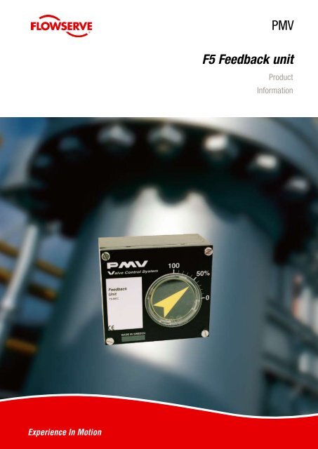
1. Jumper for field selection of 90, 60, 45 and 30 deg,operation for 4–20 mA position transmitter.2. LEDs indicate 4 and 20 mA output.3. Test outlet for 4–20 mA position transmitter.4. Info printed on the PC board.5. Field selectable direction of 4–20 mA of ouputsignal, direct or reverse.6. Easy to set cams with no fixed increments for true100% resolution.3.2.1.4. 5. 6.<strong>F5</strong> <strong>Feedback</strong> Unit<strong>F5</strong>/<strong>F5</strong>-EX• Mounts on P5/EP5 without additional mounting bracket.• Bright visible, flat or dome position indicator.• Easy to set stepless cams – 100% resolution.• Switches, mechanical or proximity, P+F Namur sensors.• Potentiometer or 4–20 mA position transmitter.• Sturdy, reliable and simple design.• Explosion proof or intrinsically safe enclosure.• ATEX, CSA and FM approvalsEasy to installInstall coupling Place <strong>F5</strong> <strong>unit</strong> on top, tighten screws Install indicator and cover
Technical dataGeneralConduit entries2x1/2 NPT or 2xPG 13.5 (M20)Housing materialDie cast aluminumSurface treatmentED paintingWeight 0,7 kg (lbs 1,5) Ex proof = 2,1 kg (lbs 4,6)Mounting Direct on P5/EP5 and VDI/VDE 3845FastenersStainless A2/A4Terminals2,5 mm² (AWG 14) Screw terminalsEnclosure IP66, NEMA 4Temp*–40°C to 85°C (–40°F to 185°F)Switches, mechanicalTypeRatingMechanical SPDT V36/2,5A 250 V ACNAMUR sensorsTypeP+F NJ2 V3NLoad Current< 1mA > 3 mAVoltage range5–25 V DCHysteresis 0,2%Temp–25°C to 85°C (–4°F to 185°F)Proximity switchesContact ratingMaximum operating timeBreakdown voltageContact resistanceSwitch typeMechanical and electrical life2 W or 2 VA @ 30 V DC/V AC, 0.1 A0.5 milliseconds200 V DC0.2 OhmsSPDT hermetically sealed in one <strong>unit</strong>> 10 million operationsPotentiometerOutput 5kΩ (4kΩ at 90°)ElementsConductive plasticPower rating at 70°1 WLinearity 1%ResolutionEssentially infinite4-20 mA position transmitterPower supplyMax. 28 V DCOutput signal4–20 mALED indication at 4 mA ±1%LED indication at 20 mA ±1%ResolutionInfiniteMinimum rotation travel 30°Maximum rotation travel90° (270° option)Linearity
Modular<strong>F5</strong> mounted on actuator for on/off applications<strong>F5</strong> mounted on positioner P5<strong>F5</strong> mounted on positioner EP5<strong>F5</strong> Series CodingModel (for installation on P5/EP5 only)<strong>F5</strong>G <strong>F5</strong> with PG 13.5 connections<strong>F5</strong>N <strong>F5</strong> with NPT 1/2” connectionsSurface treatmentU Epoxy, EDM TuframSwitchesMEC 2 x SPDT switchesNAM 2 x P+F Namur SensorsPXY 2 x Proximity switches<strong>Feedback</strong>XXX NonePOT Potentiometer 5 kOhmtP1K Potentiometer 1 kOhmP18 Potentiometer 180 deg420 4–20 mA transmitterT18 4-20 mA tranmitter, 180 degT27 4-20 mA transmitter, 270 degSpindle00 Drive coupling for P5/EP5SealsZ Nitrile, NBRModel<strong>F5</strong>IS <strong>F5</strong> Intrinsically safe<strong>F5</strong>EX <strong>F5</strong> Explosion proofElectrical connectionsG PG13.5, Not <strong>F5</strong>EXZ 1/2” NPTSurface treatmentU Epoxy, EDM TuframSwitchesMEC 2 x SPDT switchesNAM 2 x P+F Namur SensorsPXY 2 x Proximity switches<strong>Feedback</strong>XXX NonePOT Potentiometer 5 kOhmtP1K Potentiometer 1 kOhmP18 Potentiometer 180 deg420 4–20 mA transmitterT18 4-20 mA tranmitter, 180 degT27 4-20 mA transmitter, 270 degSpindle00 Drive coupling for P5/EP523 01 to 39, see dwg SPNDLS_P5Frontcover, indicatorPV9DA 90 deg, direct arrow indicatorPV3RH 30 deg, reverse, Dome indicatorSealsZ Nitrile, NBRExample<strong>F5</strong>ISNU-MEC420-00-PV9DA-Z(*For 30, 45, 60 deg rotation, change PV9 to PV3, PV4 or PV6 D=direct, R=reverse,A=arrow indicator, B=blind, H=dome)
Dimensions drawings (mm)<strong>F5</strong><strong>F5</strong> with Dome H5<strong>F5</strong> on EP5<strong>F5</strong>EX on EP5EX
p/n: FCD PMENBR0005-02Hazardous LocationsIntrinsically safe:ATEX II 1 G, EEx ia IIC T4 LCIE 95.D6 IIIX CSA, FM Class 1, Div 1,Group C, D T3C ATEXExplosion proof:ATEX II 1 G, EEx d IIB+H2, T4-T6 LCIE 97.D6140 IIIX CSA, FM Div 1,Class 1,2 & 3 Group BCDEFG T4-T6, ATEXPalmstierna International ABKorta Gatan 9SE-171 54 SolnaSWEDENTel: +46 (0) 8 555 106 00Fax: +46 (0) 8 555 106 01E-mail: infopmv@flowserve.comGermanyFlowserveSperberweg 16D-41468 NeussGERMANYTel: +49 (0) 2131 795 74 80Fax: +49 (0) 2131 795 74 99E-mail: pmvgermany@flowserve.comUKFlowserveAbex RoadNewbury, Berkshire, RG14 5EYUKTel: +44 (0) 1635 46 999Fax: +44 (0) 1635 36 034E-mail: pmvukinfo@flowserve.comItalyFlowserve SpaVia Prealpi, 3020032 Cormano (Milano)ITALYTel: +39 (0) 2 663 251Fax: +39 (0) 2 615 18 63E-mail: infoitaly@flowserve.comUSA, Mexico<strong>PMV</strong>-USA1440 Lake Front Circle, Unit 160The Woodlands, TX 77380USATel: +1 281 292 7500Fax: +1 281 292 7760E-mail: pmvusa@flowserve.comCanadaCancoppas Limited2595 Dunwin Drive, Unit 2Mississuga, Ont L5L 3N9CANADATel: +1 905 569 6246Fax: +1 905 569 6244E-mail: controls@cancoppas.comRätt Grafiska AB Ordernr: 20971Flowserve Corporation has established industry leadership in the design and manufacture of its products. When properly selected, this Flowserve product is designed to perform its intended function safelyduring its useful life. However, the purchaser or user of Flowserve products should be aware that Flowserve products might be used in numerous applications under a wide variety of industrial service conditions.Although Flowserve can (and often does) provide general guidelines, it cannot provide specific data and warnings for all possible applications. The purchaser/user must therefore assume the ultimateresponsibility for the proper sizing and selection, installation, operation, and maintenance of Flowserve products. The purchaser/user should read and understand the Installation and Maintenance (I & M)instructions included with the product, and train its employees and contractors in the safe use of Flowserve products in connection with the specific application.While the information and specifications contained in this literature are believed to be accurate, they are supplied for informative purposes onlyand should not be considered certified or as a guarantee ofsatisfactory results by reliance thereon. Nothing contained herein is to be construedas a warranty or guarantee, express or implied, regarding any matter with respect to this product. Because Flowserve iscontinually improving andupgrading its product design, the specifications, dimensions and information contained herein are subject to change without notice. Should any question arise concerning theseprovisions, the purchaser/user should contact Flowserve Corporation at any one of its worldwide operations or offices.©2007 Flowserve Corporation, Irving, Texas, USA. Flowserve and <strong>PMV</strong> are registered trademarks of Flowserve Corporation.Asia Pacific HeadquartersFlowserve Pte Ltd.No. 12 Tuas Avenue 20REPUBLIC OF SINGAPORE 638824Tel: +65 (0) 687 98900Fax: +65 (0) 686 24940South AfricaFlowserveUnit 1, 12 Director RoadSpartan Ext. 21613 Kempton Park, GautengSOUTH AFRICATel: +27 (0) 11 397 3150Fax: +27 (0) 11 397 5300The NetherlandsFabromatic BVRechtzaad 174703 RC RoosendaalTHE NETHERLANDSTel: +31 (0) 30 6771946Fax: +27 (0) 30 6772471E-mail: fcbinfo@flowserve.comChinaFlowserveHanwei BuildingNo. 7 Guanghua RoadChao Yang District100004 BeijingCHINATel: +86 (10) 6561 1900Fax: +86 (10) 6561 1899www.pmv.nu