Undergraduate Laboratory Experiments in Ku-Band Radio Astronomy
Undergraduate Laboratory Experiments in Ku-Band Radio Astronomy
Undergraduate Laboratory Experiments in Ku-Band Radio Astronomy

You also want an ePaper? Increase the reach of your titles
YUMPU automatically turns print PDFs into web optimized ePapers that Google loves.
TAMKE-ALLAN OBSERVATORY<strong>Undergraduate</strong> <strong>Laboratory</strong> <strong>Experiments</strong> <strong>in</strong> <strong>Ku</strong>-<strong>Band</strong> <strong>Radio</strong><strong>Astronomy</strong>: A Very Small <strong>Radio</strong> Telescope InterferometerVSRTD A V I D E . F I E L D ST A M K E - A L L A N O B S E R V A T O R YR O A N E S T A T E C O M M U N I T Y C O L L E G EA L A N E . E . R O G E R SP R E E T H I P R A T A PP H I L L I P S C H U T EH A Y S T A C K O B S E R V A T O R YM A S S A C H U S E T T E S I N S T I T U T E O F T E C H N O L O G Y
U N D E R G R A D U A T E L A B O R A T O R Y E X P E R I M E N T S I N KU- B A N D R A D I O A S T R O N O M YA Very Small <strong>Radio</strong> TelescopeInterferometer
Table of ContentsACKNOWLEDGEMENTS 61 7Introduction 7This is a heuristic manual. The student must be ready to experiment, question and th<strong>in</strong>k. 7Interferometery 7To the student 8Current web resources 8A selected historical bibliography 92 11Familiarization with Components 11A set of basic components will be provided. They will be chosen from currently availablegeneric devices and may vary somewhat <strong>in</strong> operat<strong>in</strong>g parameters. As <strong>in</strong> life, you must be readyto question and learn. 11Component list and function 11LNB characterization 12DC power <strong>in</strong>jector 14In-l<strong>in</strong>e amplifier characteristics 15Frame grabber function 15Envelope detector importance 153 18Software Components and Installation 18Key components of the VSRT software are the analysis code, the frame grabber driver and Java<strong>in</strong>terface, and the control parameter file (used by control functions of the analysis code). For properoperation, software components must be <strong>in</strong>stalled on the PC by the <strong>in</strong>structor or the studentaccord<strong>in</strong>g to the follow<strong>in</strong>g procedure. 18Frame grabber software 182
Analysis and control software 18A reference map for student measurements 19Installation of frame grabber and analysis software 20Control parameter file srt.cat 21srt.cat file for Westford, MA 22srt.cat file as modified for use at TAO 244 29VSRT Construction 29The VSRT is a 2 or more detector system. Signals from both detectors (LNBs with or withoutdishes) are comb<strong>in</strong>ed to produce an <strong>in</strong>strument hav<strong>in</strong>g twice the capture area of a s<strong>in</strong>gle dish,and a resolution dependent on the separation of the antennas. 29Configurations 29A simple VSRT – the tw<strong>in</strong> LNB setup 29Generic VSRT configuration 31Interpretation of VSRT Output 325 33Generic Source Characterization 33A variety of sources will be used to simulate radio astronomy measurements. 33Exam<strong>in</strong>ation of 2 unmodulated sources 33A fundamentally important measurement 34Exam<strong>in</strong>ation of a s<strong>in</strong>gle unmodulated source 34Exam<strong>in</strong>ation of a s<strong>in</strong>gle modulated source 35Student measurements 356 36CFL Parameterization 36Your reference sources for many Indoor Lab <strong>Experiments</strong> will be Compact Fluorescent Lamps(CFLs). You will f<strong>in</strong>d them useful and <strong>in</strong>terest<strong>in</strong>g. 36Lamp construction, modulation, and <strong>in</strong>stability 36Student measurements – s<strong>in</strong>gle base and s<strong>in</strong>gle source 37Student Measurements – s<strong>in</strong>gle base and complex source 37Student Measurements – complex base and complex source 387 39S<strong>in</strong>gle Dish <strong>Experiments</strong> 39The VSRT has maximum utility when operated as an <strong>in</strong>terferometer; nevertheless, s<strong>in</strong>gle dishmeasurements can be very <strong>in</strong>structive. 39Sensitivity to sources 39Exploration of LNB sensitivity 39Exploration of dish/LNB sensitivity 39LNB programmability options 40Determ<strong>in</strong>ation of polarization sensitivity 40S<strong>in</strong>gle dish radiometry measurements 413
<strong>Radio</strong>metry Calculations 428 44Double Antenna <strong>Experiments</strong> 44A serious VSRT is a tw<strong>in</strong>-antenna system for exam<strong>in</strong><strong>in</strong>g celestial sources. Signals from bothantennas are comb<strong>in</strong>ed to produce an <strong>in</strong>strument hav<strong>in</strong>g twice the capture area of a s<strong>in</strong>gle dish,and a resolution dependent on the separation of the antennas. 44Celestial sources 44Calibration of the 2-element <strong>in</strong>terferometer. 44Intensity function of relative temperature 44Measurements of relative temperature 45Correction for beam fill<strong>in</strong>g fraction 45Student fill<strong>in</strong>g fraction measurement 459 47Null<strong>in</strong>g a Complex Source 47A simple double-source experiment will demonstrate the phase sensitivity of the VSRT <strong>in</strong> 2-detector configuration. Counter-<strong>in</strong>tuitive results can be most <strong>in</strong>structive. 47Experimental setup 47Total Power Measurements 4710 51Antenna Mounts and Track<strong>in</strong>g 51Mounts take many forms. The most important criterion for these exercises is that yourmount<strong>in</strong>g arrangement be mechanically stable and reproducible. 51Criteria for simple mounts 51Steerable mounts -- exercise 51Track<strong>in</strong>g 53Student exercise -- po<strong>in</strong>t<strong>in</strong>g 5411 55Solar StudiesError! Bookmark not def<strong>in</strong>ed.To effectively study the sun, it is helpful to track it, thus provid<strong>in</strong>g time for averag<strong>in</strong>g thesignal and study<strong>in</strong>g transient phenomena. If one has available the VSRT track<strong>in</strong>g hardware, itmay be employed to acquire, track and exam<strong>in</strong>e various sources. Temperature may bedeterm<strong>in</strong>ed by an absolute measurement. 55Acquir<strong>in</strong>g the sun with a dish or <strong>in</strong>terferometer 55Absolute temperature determ<strong>in</strong>ation 55Measurement of absolute absorber temperature 56Measurement of absolute solar temperature 56References 5612 58Sensitivity 584
Sensitivity determ<strong>in</strong>es what sources may be profitably exam<strong>in</strong>ed. A s<strong>in</strong>gle-dish and VSRT<strong>in</strong>terferometer will be considered. 58Importance of sensitivity considerations 58Multi-antenna sensitivity 59Sample Calculation of detectability 60Example calculation 61Extension of <strong>in</strong>tegration time 6113 62Solar Studies 62The sun may be exam<strong>in</strong>ed as to overall flux, polarization, and structure.. 62Suitability of the sun for study 62Solar flux measurements 62Solar circular polarization measurements 62Solar l<strong>in</strong>ear polarization measurements 64Solar raster images 65Scann<strong>in</strong>g fixed extended objects 65Scann<strong>in</strong>g orbit<strong>in</strong>g celestial objects 65Tropospheric sc<strong>in</strong>tillation measurements 66References 6614 67<strong>Ku</strong> band Satellite Studies 67Satellite signals may be both a source of test and setup signals, and a source of <strong>in</strong>terference. 67Satellite signals 67Scann<strong>in</strong>g us<strong>in</strong>g the VSRT 67Clarke belt structure 67Satellite circular polarization measurements 67Tropospheric sc<strong>in</strong>tillation measurements 6815 69Phase Closure 69A closure phase may be computed for 3 or more detectors and shown to be 0 or 180 degrees.Its actual value is sensitive to the symmetry of the source. This technique can be developed tomake sensitive and sophisticated measurements. 69Student validation of phase closure 70Student demonstration of phase closure failure 7116 72Corrections, Addenda, and Notes 72Students are <strong>in</strong>vited to record their comments on this page and to send them to the authors forconsideration <strong>in</strong> future experiment manuals. Notations of errors and suggestions forimprovements will be greatly appreciated.. 725
AcknowledgementsS<strong>in</strong>cere thanks are extended to Bill Lord and Heather Fries for work<strong>in</strong>g with us onequipment setup and configuration and <strong>in</strong> help<strong>in</strong>g evaluate potential experiments to selectthe most effective approaches. Thanks go also to students at Tamke-Allan Observatory,Roane State Community College, who tested the experiments and offered helpfulsuggestions.The authors6
FEBRUARY 2008Experiment1IntroductionThis is a heuristic manual. The student must be ready to experiment,question and th<strong>in</strong>k.InterferometeryThis is an <strong>in</strong>troductory laboratory manual for experiments <strong>in</strong> <strong>in</strong>terferometry, with anemphasis on techniques useful <strong>in</strong> radio astronomy. An <strong>in</strong>terferometer is an <strong>in</strong>strumentthat comb<strong>in</strong>es two signals (normally from two detectors) <strong>in</strong> a manner that the signals<strong>in</strong>terfere to produce a resultant signal. The resultant signal is usually the vector sum of thetwo signals, but <strong>in</strong> some cases it is the product or some other mix. The traditional<strong>in</strong>terferometer, usually studied and analyzed <strong>in</strong> physics courses, comb<strong>in</strong>es the two signals<strong>in</strong> a way that both amplitude and phase <strong>in</strong>formation are used. By vary<strong>in</strong>g the positions ofthe two detectors, it is possible to synthesize an effective aperture that is equivalent to theseparation of the detectors and to reconstruct the imp<strong>in</strong>g<strong>in</strong>g wavefront, thus provid<strong>in</strong>gsignificant <strong>in</strong>formation about the extent and structure of the signal source. Thetraditional phase-sensitive <strong>in</strong>terferometer requires retention of the signal phase at eachdetector – the phase-sensitive <strong>in</strong>terferometry technique will not be discussed <strong>in</strong> detailhere.A special case of the <strong>in</strong>terferometer is the <strong>in</strong>tensity <strong>in</strong>terferometer, which performs an<strong>in</strong>tensity correlation of signals from the two detectors. Although <strong>in</strong> the <strong>in</strong>tensity<strong>in</strong>terferometer the phase <strong>in</strong>formation from the two antennas is discarded, the correlationof the two signals rema<strong>in</strong>s useful. Aperture synthesis is not practical, but some importantsource characteristics may be determ<strong>in</strong>ed.The VSRT <strong>in</strong>terferometeric techniques developed here <strong>in</strong> <strong>Experiments</strong> 1-13 describe an<strong>in</strong>tensity <strong>in</strong>terferometer.If the number of detectors <strong>in</strong> is greater than two, then the signals of the several detectorsmay be comb<strong>in</strong>ed mathematically to effectively recover some of the relative phase<strong>in</strong>formation from the detectors and to yield very useful results. This technique, called thephase closure technique, can produce results approach<strong>in</strong>g that of a phase sensitive7
FEBRUARY 2008<strong>in</strong>terferometer. The closure phase is <strong>in</strong> theory unaffected by phase errors occurr<strong>in</strong>g at thedetectors. It is widely used for aperture synthesis imag<strong>in</strong>g <strong>in</strong> astronomical <strong>in</strong>terferometryand for process<strong>in</strong>g recorded signals obta<strong>in</strong>ed from antennas separated by large distances.Phase closure will be discussed <strong>in</strong> Experiment 14.To the studentIt is imperative that the student ma<strong>in</strong>ta<strong>in</strong> his/her own lab record book. Buy acomposition book and record sufficient <strong>in</strong>formation that you and your <strong>in</strong>structor canunderstand or recreate your setup and your results. This is an undergraduate lab manualthat uses relatively few components to develop basic understand<strong>in</strong>g of concepts suitablefor an <strong>in</strong>troduction to radio concepts of Physics, <strong>Radio</strong> <strong>Astronomy</strong>, or <strong>Ku</strong>-bandEng<strong>in</strong>eer<strong>in</strong>g.Each experiment should be completed and understood before the next is undertaken.Each experiment record must conta<strong>in</strong> name, partners, date, equipment layout,observations and f<strong>in</strong>d<strong>in</strong>gs. F<strong>in</strong>d<strong>in</strong>gs, conclusions, and comments should follow.Current web resourcesThe primary reference source for the VSRT experiments is the set of memos prepared byA. Rogers and his colleagues. They may be found athttp://www.haystack.mit.edu/edu/undergrad/VSRT/VSRT_Memos/memo<strong>in</strong>dex.htmlA complimentary web resource is the larger set of <strong>Radio</strong> <strong>Astronomy</strong> resources fromHaystack Observatory, entitled “<strong>Radio</strong> <strong>Astronomy</strong> Tutorial”, found athttp://www.haystack.mit.edu/edu/undergrad/materials/RA_tutorial.htmlThe limited bibliography at the end of this section is an attempt to select somebackground references that will give the student a perspective on the development ofradio astronomy, <strong>in</strong> particular that associated with <strong>in</strong>terferometeric observations. Thecitations are good ones, but not very current. A more complete list of citations may befound at http://nedwww.ipac.caltech.edu/level5/Rayburn/Rayburn4.htmlIf the student has difficulty <strong>in</strong> locat<strong>in</strong>g a desired reference, then it may be borrowed; tothis end, a comprehensive list of <strong>Astronomy</strong>-related libraries may be accessed athttp://www.cv.nrao.edu/fits/www/yp_library.htmlF<strong>in</strong>ally, amateur radio astronomers can be sources of knowledge and assistance, and theiractivities are summarized at http://radio-astronomy.org/8
FEBRUARY 2008A selected historical bibliographyBayl<strong>in</strong>, Maddox, and McCormac, World Satellite TV and Scrambl<strong>in</strong>g Methods: TheTechnicians‟ Handbook, 2nd ed. (1991) Bayl<strong>in</strong> Publications,.Broten, N.W., Legg, T.H., Locke, J.L., McLeish, C.W., Richards, R.S., Chisholm, R.M.,Gush, H.P., Yen, J.L., Galt, J.A., "Long base l<strong>in</strong>e <strong>in</strong>terferometry: a new technique", (1967)Science 156: 1592-1593.Brown, R.H., "The Intensity Interferometry - its application to astronomy", (1974)London: Taylor & Francis.Hey, J.S., "The Evolution of <strong>Radio</strong> <strong>Astronomy</strong>" (1973) New York: Science History Publ.Jansky, C.M. Jr., "My brother Karl Jansky and his discovery of radio waves from beyondthe earth" (1979 fall) Cosmic Search 1: 12-16 .Jennison, Roger, “A phase sensitive <strong>in</strong>terferometer technique for the measurement of theFourier transforms of spatial brightness distributions of small angular extent” (1958),Monthly Notices of the Royal Astronomical Society 118 pp 276 ff.Kandu, M.R., “<strong>Radio</strong> Physics of the Sun”, Proceed<strong>in</strong>gs of the Symposium, College Park,MD, August 7-10., (1980) Dordrecht, D. Reidel Publ. Co pp158-169.Kandu, M.R., Solar <strong>Radio</strong> <strong>Astronomy</strong>, (1965) Interscience Publishers, New York .Kraus, J., "The first 50 years of radio astronomy, part 3: Post-war radio astronomy",(1983) Astro Search 1: 5-6.Kraus, J., "Big Ear", (1976) Columbus: Cygnus Books.Kraus, J., "The first 50 years of radio astronomy, part 1: Karl Jansky and his discovery ofradio waves from our galaxy", (1981 fall) Cosmic Search 3: 8-12.Kraus, J., "The first 50 years of radio astronomy, part 2: Grote Reber and the first radiomaps of the sky" (1982 first half) Cosmic Search 4: 14-19.Kraus, J.D., "<strong>Radio</strong> <strong>Astronomy</strong>", (1966) New York: McGraw-HillKraus, J.D., "Recent advances <strong>in</strong> radio astronomy", (1964 Sept.) IEEE Spectrum 1: 78-95.<strong>Ku</strong>ndu, Mukul R., Solar <strong>Radio</strong> <strong>Astronomy</strong>, The <strong>Radio</strong> <strong>Astronomy</strong> Observatory, (1965)The University of Michigan, Ann Arbor, Michigan, Interscience Publishers,Lonc, W., <strong>Radio</strong> <strong>Astronomy</strong> Projects, 2 nd Edition (2003) <strong>Radio</strong>-Sky Publish<strong>in</strong>g.9
FEBRUARY 2008Lovell, B. "Out of the Zenith",(1973) Oxford: University Press.Lovell, B., "The Story of Jodrell Bank", (1968) New York: Harper & Row.Nita, G. M., D. Gary and L. Lanzerotti, (2004) Space Weather Journal 2 S11005.Penzias, A.A., Wilson, R.W., "A measurement of excess antenna temperature at 4080Mc/s", (1965) Astrophys. J. 142: 419-421.Smerd, S. F., “<strong>Radio</strong>-Frequency Radiation from the Quiet Sun.”, (August 30, 1949).Division of <strong>Radio</strong>physics, C.S.I.R.O., University Grounds, Sydney.Sullivan, W.T. III, "A new look at Karl Jansky's orig<strong>in</strong>al data", (1978) Sky and Telescope.56: 101-105Sullivan, W.T. III, "<strong>Radio</strong> astronomy's golden anniversary", (1982) Sky andTelescope. 64: 544-550.Swenson, G.W. Jr., Mathur, N.C., "The <strong>in</strong>terferometer <strong>in</strong> radio astronomy", (1968) Proc.IEEE 56: 2114-2130.Westerhout, G., "The early history of radio astronomy", (1972) Annals N.Y. Acad. Sci.198: pp 211-218.Wilson, R.W., "The cosmic microwave background", (1979) Rev. Mod. Phys. 51: 435-445.10
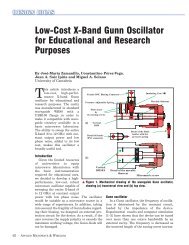
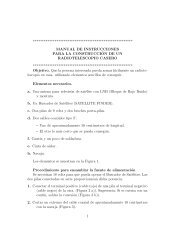
D E S I G N C U S T O M I Z A T I O NExperiment2Familiarization withComponentsA set of basic components will be provided. They will be chosen fromcurrently available generic devices and may vary somewhat <strong>in</strong> operat<strong>in</strong>gparameters. As <strong>in</strong> life, you must be ready to question and learn.Component list and functionA kit conta<strong>in</strong><strong>in</strong>g the components listed below will be provided. Be sure that youcan identify the components shown and know their function. This kit ofequipment will be sufficient for the <strong>in</strong>itial set-up of a s<strong>in</strong>gle basel<strong>in</strong>e (2 dish) VerySmall <strong>Radio</strong> Telescope (VSRT) <strong>in</strong>terferometer.Description18"x20" DIRECTV Satellite Dish Antenna with 3 dual LNBs WNC2-, 3-, or 4-way <strong>Ku</strong> band splitter with DC pass all portsSeveral In-l<strong>in</strong>e amplifiersPower <strong>in</strong>jectorsCompUSA Video Grabber or equivalent, USB 2.012-15v AC-to-DC power supply3-amp barrel diodesMale-to-male "F" connector adapters
FEBRUARY 2008"F" connector to BNC jack adapterCoaxial Adapter, BNC female / RCA maleDetector diodes or pre-assembled envelope detector us<strong>in</strong>g high-frequency diodes,e.g. 1N6263Coax cables with F connectors100pt capacitor 272-123 1 <strong>Radio</strong> ShackCompact Fluorescent LampsLNB characterizationLNB is an acronym for Low Noise Block converter. Each receiver head normallyconsists of one or more LNB receiver units with its own local oscillator, mixer, amplifierand filters. A functional diagram is presented <strong>in</strong> Figure 1. .Each LNB accepts signals overa broad band from about 11.5 to 13.2 GHz and this block is mixed with a local oscillatorsignal of about 11 GHz. Thus the output block conta<strong>in</strong>s a range of IntermediateFrequency (IF) signals extend<strong>in</strong>g from about 0.3 to 2 GHz.Figure 1. Block diagram of an LNB.The LNB is the device on the front of a satellite dish that receives the very low levelmicrowave signal from the satellite, amplifies it, changes the signals to a lower frequencyband and sends them down the cable to the <strong>in</strong>door receiver. Nom<strong>in</strong>al signal frequenciesare as follows <strong>in</strong> Figure 2:12
FEBRUARY 2008Inputfrequencyband fromsatellitewaveguideInput band(GHz)Local Oscillator (LO)frequency (GHz)Output L bandfrequency (MHz).<strong>Ku</strong> band 10.7-11.7 9.75 950-195010.95-11.7 10 950-170010.95 - 12.15 10 950-215011.45-11.95 10.5 950-145011.2-11.7 10.25 950-145011.7-12.75 10.75 950-200012.25-12.75 11.3 950-145011.7-12.75 10.6 1100-2150Figure 2. Example Input and output frequencies of selected LNB.Some functions of the LNB are set by the DC voltage supplied to it, normally <strong>in</strong> therange 11-18 volts. The DC voltage is fed <strong>in</strong>to the coaxial output connector us<strong>in</strong>g a DC<strong>in</strong>jector.LNBs are designed to be able to select satellite signals accord<strong>in</strong>g to frequency andpolarization (Right Hand Circular Polarization, RCP or Left Hand Circular, LCP). This isaccomplished by send<strong>in</strong>g various control signals, typically the specific DC voltage leveland a 22 kHz signal (present or absent) up along the coax cable to the LNB, as shown <strong>in</strong>Figure 3. Programmability options vary accord<strong>in</strong>g to brand and model. S<strong>in</strong>ce the DirectTV assembly is very common, it will be presented as an example. The importance ofthese programm<strong>in</strong>g options will become apparent later <strong>in</strong> this manual where vary<strong>in</strong>g DClevels will be used to control LNB polarization sensitivity.Figure 3. Programm<strong>in</strong>g options for the Direct TV feed assembly with 3 <strong>Ku</strong> band dualLNBs13
FEBRUARY 2008If one is us<strong>in</strong>g comb<strong>in</strong>ed <strong>Ku</strong>/Ka Direct TV LNBs, then the follow<strong>in</strong>g characteristics (seeFigure 4) will be obta<strong>in</strong>ed:Figure 4. Programm<strong>in</strong>g options for the Direct TV feed assembly with comb<strong>in</strong>ed <strong>Ku</strong>/Kasensitivity.DC power <strong>in</strong>jectorThe DC <strong>in</strong>jector provides power for <strong>in</strong>-l<strong>in</strong>e amplifiers and the LNB. As shown <strong>in</strong> Figure5, it connects to an external power source and is isolated from the RF signal path by ahigh impedance <strong>in</strong>ductor. The RF is transmitted through the DC <strong>in</strong>jector by a coupl<strong>in</strong>gcapacitor.Figure 5. Schematic of a typical power <strong>in</strong>jector. As shown here, the right side of thedevice is the upstream side.The port of the <strong>in</strong>jector labeled „SIGNAL + DC” (shown <strong>in</strong> Figure 5 on the right side)must connect upstream, toward the antenna, where it will power the LNB and any <strong>in</strong>-l<strong>in</strong>eamplifiers. In some cases, upstream component function will be controlled by DC leveland either the power supply voltage must be varied, or diodes may be connected <strong>in</strong> serieswith the supply to drop the voltage by approximately 0.5-0.7 VDC per diode.Care must be taken to avoid rout<strong>in</strong>g DC levels to the envelope detector, which may beharmed if this occurs.14
FEBRUARY 2008In-l<strong>in</strong>e amplifier characteristicsIn-l<strong>in</strong>e amplifiers receive DC current through the coax. The DC <strong>in</strong>jector is located“downstream” of the amplifier. RF enters on the upstream side (the antenna side) andthe amplified signal proceeds downstream, toward the receiver – <strong>in</strong> this case the envelopedetector and the USB video digitizer.Amplifiers may be cascaded up to the po<strong>in</strong>t that they beg<strong>in</strong> to oscillate. Table 1 lists sometypical amplifiers that you may have <strong>in</strong> your kit of parts, and the specified ga<strong>in</strong> of eachtype.Table 1. List of some typical <strong>in</strong>-l<strong>in</strong>e amplifier characteristics.Frame grabber functionA frame grabber consist<strong>in</strong>g of an analogue processor, analogue to digital converter andassociated tim<strong>in</strong>g and <strong>in</strong>terfac<strong>in</strong>g components digitizes the signal from the <strong>in</strong>tegrator andmakes it available to the driver program runn<strong>in</strong>g <strong>in</strong> the PC.Envelope detector importanceAn envelope detector is used to rectify and smooth the vary<strong>in</strong>g signal after process<strong>in</strong>g bythe amplifiers. It must follow the DC power <strong>in</strong>jector and must be isolated from circuitDC levels. There are several possible configurations of the envelope detector, with onepossible configuration shown <strong>in</strong> Figure 6.Figure 6. Envelope detector. This is one of several useful variations. The circuit rectifiesand performs as a square law detector.15
FEBRUARY 2008It is helpful to construct the envelope detector <strong>in</strong> a small box to avoid a flexible circuitwith higher probability of component lead failure. Two variations of the envelopedetector are shown <strong>in</strong> Figure 7. The photograph on the left shows the circuit of Figure 6,while photograph on the right shows another variation, where the grounded diode isreplaced by an air-core <strong>in</strong>ductor that ma<strong>in</strong>ta<strong>in</strong>s a ground-reference DC level, butpreserves the (RF) analogue component.Figure 7. Photographs of two variations of the envelope detector.The envelope detector has several functions. First, the envelope detector conditions thesignal for digitization by the video frame grabber. The high frequency L-bandcomponents com<strong>in</strong>g from the signal splitter and through the amplifiers are shunted toground, while the video digitizer responds to signals below about 5 MHz.Second, the envelope detector has power characteristics that make it useful for powercomparisons; i.e., it functions as an (approximate) square law detector. The device (asdeterm<strong>in</strong>ed by the diode oriented horizontally <strong>in</strong> Figure 6) exhibits a power law that isaround the ideal square law at 0 dBm but becomes greater than square at lower levels andis close to a l<strong>in</strong>ear voltage detector at high levels. These experiments will be performed atlow signal levels for which the response is approximate square law as suggested <strong>in</strong>Figure 816
FEBRUARY 2008Figure 8. Power law characteristics of diode envelope detector operated at low forwardvoltage.While the deviation from a square law at higher signal levels will result <strong>in</strong> errors <strong>in</strong> totalpower measurement and a degradation <strong>in</strong> signals to noise ratio (SNR), the error will besmall on both the relative signal strengths of the fr<strong>in</strong>ges from a 2 detector (or more)basel<strong>in</strong>e <strong>in</strong>terferometer constructed as discussed <strong>in</strong> Experiment 4 and developed <strong>in</strong>succeed<strong>in</strong>g <strong>Experiments</strong>.17
FEBRUARY 2008Experiment3Software Components andInstallationKey components of the VSRT software are the analysiscode, the frame grabber driver and Java <strong>in</strong>terface, and thecontrol parameter file (used by control functions of theanalysis code). For proper operation, software componentsmust be <strong>in</strong>stalled on the PC by the <strong>in</strong>structor or the studentaccord<strong>in</strong>g to the follow<strong>in</strong>g procedure.Frame grabber softwareThe function of the frame grabber is to perform a high-speed analogue to digitalconversion.Frame Grabber Software has been written to <strong>in</strong>terface with the analysis program. It ismuch different than the standard frame grabber software. The specialized frame grabbersoftware must be <strong>in</strong>stalled prior to connect<strong>in</strong>g the device; otherwise <strong>in</strong>dustry-standarddrivers will be <strong>in</strong>stalled and the device will not operate as <strong>in</strong>tended for VSRT <strong>in</strong>put. Touse the new software, a USB software <strong>in</strong>terface must be present. This <strong>in</strong>terface is JcommUSB API Personal Edition 1. It is available from www.Icaste.com and must also be<strong>in</strong>stalled It will permit output of the video frame grabber to be routed to the analysissoftware.Analysis and control softwareAnalysis software consists of a Java code that performs both signal analysis and mountcontrol functions. Real-time data acquisition results and control parameters are presented18
FEBRUARY 2008on the PC screen. Typical results are displayed by the graphical user <strong>in</strong>terface (GUI)display shown <strong>in</strong> Figure 9.Figure 9. Analysis Software GUI explanation.A reference map for student measurementsThe usefulness of Figure 9 will become apparent as the student performs experiments,makes measurements and <strong>in</strong>terprets the results. The student must ensure that the timeseries data do not appear truncated or clipped. Useful frequency data will be displayed (ifof sufficient power) <strong>in</strong> the Power vs. Frequency frame. This is the basic Power Spectrumdisplay frame. The time-averaged version of this frame appears <strong>in</strong> the Av. PowerSpectrum (red background) frame. Scan plots of sources will appear <strong>in</strong> the Scan Plotframe. A record of experimental results over the course of several m<strong>in</strong>utes appears <strong>in</strong> thePeak Power vs. Time frame.If track<strong>in</strong>g is <strong>in</strong> progress, reception direction (beam coord<strong>in</strong>ates) will appear <strong>in</strong> theReception Beam Coord<strong>in</strong>ates frame. Site location, Track<strong>in</strong>g Status, VSRT analysis results,Detector Info, Clock Time, and Source Info Frames also appear.19
FEBRUARY 2008Installation of frame grabber and analysis softwareDo NOT plug <strong>in</strong> the USB frame grabber yet. If you do, you risk load<strong>in</strong>g defaultframe grabber drivers rather than the driver that is required for operation of the Javaprogram.Please take care to <strong>in</strong>stall the SRT/VSRT software <strong>in</strong> the root directory of your bootdrive (normally C:\) and not <strong>in</strong> the programs directory.1. Download the SRT/VSRT software.2. After you download the SRT/VSRT Install.exe file, click on "My Computer" onyour desktop (or <strong>in</strong> the START menu), then f<strong>in</strong>d the directory where the <strong>in</strong>stall.exe file islocated and left click on the file name.3. An <strong>in</strong>stall program will open and a menu driven w<strong>in</strong>dow will appear. SELECTC:\SRTv as the directory <strong>in</strong> which to <strong>in</strong>stall the SRT/VSRT software. NOTE: DO NOTINSTALL THE SRT/VSRT EXECUTABLE IN THE "PROGRAM FILES"DIRECTORY4. You will then be prompted to select the location for VSRT Icon. SELECT "On theDesktop"5. When the Installation is complete, the SRT/VSRT <strong>in</strong>stallation w<strong>in</strong>dow will rema<strong>in</strong>on the screen until you click on the DONE button. There will also be a w<strong>in</strong>dow ask<strong>in</strong>gyou to accept a license for a MS C++ library. Click YES. A short activity of load<strong>in</strong>g theC++ libraries should take a few m<strong>in</strong>utes or less.6. You should now plug <strong>in</strong> you USB frame-grabber hardware.20
FEBRUARY 20087. The W<strong>in</strong>dows "Hardware Install Wizard" will open automatically when it detects theUSB Hardware.Question 1: "Can W<strong>in</strong>dows connect to W<strong>in</strong>dows Update to <strong>in</strong>stall software?"Select: No, not at this timeQuestion 2: "What do you want the wizard to do?"Select: Install from a list or specific location [advanced]Under "Search for the best driver <strong>in</strong> these locations"Check: "Include this location <strong>in</strong> the search"Browse and enter the SRT/VSRT Install directory <strong>in</strong> the dialog box.Example: C:\VSRTOr whatever name you assigned. The necessary files needed by the wizard will havebeen loaded with the VSRT softwareClick: NextYou will then see the wizard perform<strong>in</strong>g the file transfer. When the transfer iscomplete,Click: F<strong>in</strong>ish8. You are now ready to open your VSRT console!9. Click on the SRT/VSRT Icon now on the Desktop.Control parameter file srt.catThe analysis code also has control functions that determ<strong>in</strong>e operation of the softwaredur<strong>in</strong>g an observ<strong>in</strong>g run. The analysis code calls the file srt.cat, which provides controlparameters.Srt.cat is a text file that conta<strong>in</strong>s keywords to set the various options and parametersneeded by the software. If a l<strong>in</strong>e starts with an “*” or “#” it is taken as a comment. Twoexamples of srt.cat will be presented here. The first is the standard code developed atHaystack for operation <strong>in</strong> Westford, MA. This file identifies the site and operat<strong>in</strong>gparameters for their configuration of the VSRT.21
FEBRUARY 2008The second example file is the file as modified for use at Tamke-Allan Observatory <strong>in</strong>Rockwood, TN.srt.cat file for Westford, MA* sample srt.cat file fro VSRT tests*SIMULATE RECEIVER - for SRT this l<strong>in</strong>e (with * removed) forces* simulation of the USB <strong>in</strong>terface to the frame grabber*SIMULATE RECEIVER*SIMULATE ANTENNA - simulate RS232 <strong>in</strong>terface to antenna motors*SIMULATE ANTENNA -4 - simulates with time 4 hours ahead*SIMULATE ANTENNA 10 - simulates with a factor of 10 speed-up <strong>in</strong> timeSIMULATE ANTENNA*VSRT 2 1000 400 - VSRT mode with frame grabber 2 stations* detector_ga<strong>in</strong>_scale=1000 plot_scale=400* these parameters should be O.K. for lab demonstrationsVSRT 2 1000 400*SG2100MOUNT - specifies the 2-axis mount with 2 SG2100 drivesSG2100MOUNT*AZFEEDOFFSET 9 - specifies the feed offset of 9 degreesAZFEEDOFFSET 9*STATION 42.5 71.5 Haystack - antenna_location latitude longitude_west nameSTATION 42.5 71.5 Haystack* source coords epoch 1950 unless specified* right ascension hr mn sc decl<strong>in</strong>ation deg mn sec name epochSOU 05 31 30 21 58 00 Crab22
FEBRUARY 2008SOU 05 32 48 -5 27 00 OrionSOU 23 21 12 58 44 00 CassSOU 00 00 00 00 00 00 SunSOU 17 42 54 -28 50 00 SgrASOU 06 29 12 04 57 00 RosettSOU 18 17 30 -16 18 00 M17SOU 20 27 00 41 00 00 CygEMNSOU 00 00 00 00 00 00 MoonSOU 00 39 00 40 30 00 Androm* synchronous satellite degrees_west name* every entry will be plotted on the screen at its designated position2* current azimuth and elevation* any plotted source can be selected by click<strong>in</strong>g on itSSAT 10 10SSAT 20 20SSAT 30 30SSAT 40 40SSAT 50 50SSAT 60 60SSAT 70 70SSAT 80 80SSAT 90 90SSAT A0 10023
FEBRUARY 2008SSAT B0 110SSAT C0 120SSAT D0 130SSAT E0 140SSAT F0 150ELLIMITS -1.0 80.0 // sg2100 - limits of antenna motion* stow position at -1 degrees elevationAZLIMITS 99.0 259.0 // sg2100 - limits of azimuth motion* stow position for SG2100 assumed at (99 + 259)/2* the LIMITS can be adjusted to correct for mount offsetsCOMM 1 /* COM 1 */ - serial port for antenna controlsrt.cat file as modified for use at TAOThis is a portion of the srt.cat file as modified for the Tamke-Allan Observatory (TAO)site near Rockwood, Tennessee. If the control parameters are not set for the actual site ofuse, target acquisition and track<strong>in</strong>g will be adversely effected.* sample srt.cat file*SIMULATE RECEIVER*SIMULATE ANTENNA*DEBUG*VSRT 3 10000 // for 3 stations = 3 basel<strong>in</strong>es*VSRT 2 1000 400 250 270VSRT 2 1000 400*ISOCHRONOUS*HH90MOUNT 10.0 4.0 Sun24
FEBRUARY 2008SG2100MOUNTAZFEEDOFFSET 9*AXISTILT 5 180 5* first word is key word* STATION: latitude longitude west <strong>in</strong> degrees* SAT: satellite ID then longitude west* SOU: source ra, dec, name, epoch*STATION 42.5 71.5 HaystackSTATION 35.8 84.6 TAO* source coords epoch 1950 unless specifiedSOU 05 31 30 21 58 00 CrabSOU 05 32 48 -5 27 00 Orion*SOU 05 42 00 -1 00 00 S8SOU 23 21 12 58 44 00 CassSOU 00 00 00 00 00 00 SunSOU 17 42 54 -28 50 00 SgrASOU 06 29 12 04 57 00 RosettSOU 18 17 30 -16 18 00 M17SOU 20 27 00 41 00 00 CygEMNSOU 00 00 00 00 00 00 Moon*SOU 21 12 00 48 00 00 G90*SOU 05 40 00 29 00 00 G180*SOU 12 48 00 28 00 00 GNpoleSOU 00 39 00 40 30 00 Androm25
FEBRUARY 2008*SOU 05 14 12 18 44 00 AC1*SOU 03 29 00 54 00 00 PULSARSSAT 10 10SSAT 15 15SSAT 20 20SSAT 25 25SSAT 30 30SSAT 35 35SSAT 40 40SSAT 45 45SSAT 50 50SSAT 55 55SSAT 60 60SSAT 65 65SSAT 70 70SSAT 75 75SSAT 80 80SSAT 85 85SSAT 90 90SSAT 95 95SSAT A0 100SSAT A5 105SSAT B0 110SSAT B5 11526
FEBRUARY 2008SSAT C0 120SSAT C5 125SSAT D0 130SSAT D5 135SSAT E0 140SSAT E5 145SSAT F0 150SSAT F5 155*SSAT DBS 102*GALACTIC 10 1 RC_CLOUD*AZEL 130 12 vane*AZLIMITS 92.0 265.0 /* mid az range is south */*AZLIMITS 78.0 359.0*ELLIMITS 5.0 175.0 /* elevation limit south - north */*ELLIMITS 10.0 175.0ELLIMITS -1.0 80.0 // sg2100AZLIMITS 99.0 259.0 // sg2100*AZLIMITS 280 80 // sg2100 for southern hemisphere*ALFASPID 1.0 1.0*CASSIMOUNT 14.25 16.5 2.0 110.0 30.0*CASSIMOUNTCOMM 1 /* COM 1 */CALCONS 0.1 /* ga<strong>in</strong> correction constant to put power <strong>in</strong> units of K */27
FEBRUARY 2008*BEAMWIDTH 7.0scans */BEAMWIDTH 4.0scans *//* 3 dB antenna beamwidth <strong>in</strong> degrees - used to set offsets for/* 3 dB antenna beamwidth <strong>in</strong> degrees - used to set offsets for*MANCAL 1 /* 0 or absence <strong>in</strong>dicates automated cal vane */*NOISECAL 200.0 /* <strong>in</strong>itial value for noise diode calibration */DIGITAL /* needed for digital receiver */TOLERANCE 1 /* optional max error <strong>in</strong> counts */* COUNTPERSTEP 50 /* optional stepped antenna motion */* RECORDFORM TAB VLSR /* optional tabs between fields and VLSR <strong>in</strong> output */*ELBACKLASH 3.0 /* optional correction for elevation backlash */28
FEBRUARY 2008Experiment4VSRT ConstructionThe VSRT is a 2 or more detector system. Signals from both detectors(LNBs with or without dishes) are comb<strong>in</strong>ed to produce an <strong>in</strong>strumenthav<strong>in</strong>g twice the capture area of a s<strong>in</strong>gle dish, and a resolutiondependent on the separation of the antennas.ConfigurationsAn <strong>in</strong>terferometer is an <strong>in</strong>strument that comb<strong>in</strong>es two signals (normally from twodetectors) <strong>in</strong> a manner that the signals <strong>in</strong>terfere to produce a resultant signal. Theresultant signal is usually the vector sum of the two signals, but <strong>in</strong> some cases it is theproduct or some other mix.. A special case of the <strong>in</strong>terferometer is the <strong>in</strong>tensity<strong>in</strong>terferometer, which performs an <strong>in</strong>tensity correlation of signals from the two detectors.The VSRT <strong>in</strong>terferometeric techniques developed here <strong>in</strong> <strong>Experiments</strong> 1-13 describe an<strong>in</strong>tensity <strong>in</strong>terferometer.Initial experiments with a s<strong>in</strong>gle LNB will be covered <strong>in</strong> Experiment 5.A simple VSRT – the tw<strong>in</strong> LNB setupThe student should setup a simple <strong>in</strong>tensity <strong>in</strong>terferometer consist<strong>in</strong>g of two bare LNBsas shown <strong>in</strong> Figure 10. The envelope detector is placed between the DC power <strong>in</strong>jectorand the USB frame grabber and is represented here as a s<strong>in</strong>gle diode.29
FEBRUARY 2008Figure 10. 2-element LNB <strong>in</strong>terferometer setup for Experiment 4. Note that the diodeshown represents the envelope detector circuit.30
FEBRUARY 2008The system should be carefully constructed with all F-connectors tightened and with thecomponents and cables affixed to a board to provide stability as shown <strong>in</strong> Figure 11.Figure 11. Components of the VSRT should be rigidly affixed to a stable platform.Generic VSRT configurationA generic VSRT configuration, with parabolic dishes, tw<strong>in</strong> LNBs, signal splitter,amplifiers, DC power <strong>in</strong>jectors with and without diode voltage offset, a low pass filter, theenvelope detector, the USB video frame grabber and the PC, is presented <strong>in</strong> Figure 12. Ingeneral the student will use a comb<strong>in</strong>ation of the components shown here. Componentfunctions are described <strong>in</strong> Experiment 2.31
FEBRUARY 2008Figure 12. Generic VSRT Block Diagram. Please see text for a discussion ofcomponents.Interpretation of VSRT OutputThe VSRT analysis software performs several functions and generates displays of results.In general the output appears as shown <strong>in</strong> Figure 9.32
FEBRUARY 2008Experiment5Generic SourceCharacterizationA variety of sources will be used to simulate radio astronomymeasurements.Exam<strong>in</strong>ation of 2 unmodulated sourcesThe simplest test of the VSRT <strong>in</strong>terferometer is to po<strong>in</strong>t one feed (or dish) at the other.The experimental setup should be that of Figure 10 shown <strong>in</strong> Experiment 4. In this, bothLNBs will share the same noise. This noise correlates the output of both LNBs andhence produces a large signal at the splitter.With the very large bandwidth of the LNB <strong>in</strong>termediate frequency (I.F.) , the correlationwill average to zero over frequency for any substantial separation of the feeds unless thesplitter output is passed through a narrow band filter. Figure 13 shows the amplitude vstime (time series) signal and the frequency spectrum for 2 LNB feeds fac<strong>in</strong>g each other.33
FEBRUARY 2008Figure 13. Time series plot and frequency plot with LNB feeds po<strong>in</strong>t<strong>in</strong>g directly towardeach other. The frequency shown, 707 KHz, is the difference frequency between the twolocal oscillators.A fundamentally important measurementThis is a fundamentally important result, <strong>in</strong> that it demonstrates that if both detectors(both LNBs) see the same noise, then this noise will correlate the output and the outputfrequency spectrum will show a peak with a frequency equal to the difference frequencyof the local LNB oscillators.Exam<strong>in</strong>ation of a s<strong>in</strong>gle unmodulated sourceAnother useful test source is the signal from a fluorescent lamp. A circle lamp or sphericalbulb is most useful as it provides a small diameter source. The frame grabber electronicscomb<strong>in</strong>ed with a few seconds of <strong>in</strong>tegration is sufficient to detect the lamp at a distanceof several feet from the feed and at much larger distances if the dish is used along withthe feed. Figure 14 shows the signal from a fluorescent circle desk lamp at a distance ofabout 2 feet from each feed. Fr<strong>in</strong>ges are too weak to be seen <strong>in</strong> the time series data butcan be clearly seen <strong>in</strong> the fr<strong>in</strong>ge rate spectrum.The frequency detected and shown here is the difference frequency of the correlatednoise from the LNBs. The source is considered unmodulated because the modulationfrequency (60 Hz, yield<strong>in</strong>g 120 pulses per second) is far below the m<strong>in</strong>imum frequencydetected by the Java software analyzer.34
FEBRUARY 2008Figure 14. Fr<strong>in</strong>ges from a circle (Circl<strong>in</strong>e) lamp exam<strong>in</strong>ed with 2 LNBs <strong>in</strong> the standard<strong>in</strong>terferometer configuration. A l<strong>in</strong>ear fluorescent lamp would give a similar pattern.Exam<strong>in</strong>ation of a s<strong>in</strong>gle modulated sourceA spiral fluorescent lamp (A&H CF20/S/41K) or Compact Fluorescent Lamp (CFL) ismore compact than a Circl<strong>in</strong>e lamp and it is a good test source, although there are someunwanted modulation spurs <strong>in</strong> this lamp around, 90 kHz. The student should exam<strong>in</strong>ethe output of a CFL us<strong>in</strong>g the VSRT.Student measurementsRecord the local oscillator difference frequency that you detect with the two LNBs fac<strong>in</strong>geach other. This is the frequency that you will see as you exam<strong>in</strong>e an unmodulated source.Exam<strong>in</strong>e the spectrum of your CFL lamp with one dish po<strong>in</strong>ted at the CFL and the otherdish po<strong>in</strong>ted away. Record this as the frequency of your CFL lamp. This measurementmust be made after the CFL has operated for 5 m<strong>in</strong>utes. There also will be changes <strong>in</strong> thisfrequency as the lamp ages. CFL lamps will be discussed briefly here and considered moredeeply <strong>in</strong> Experiment 6.Some CFLs exhibit a periodic variation <strong>in</strong> RF output with a period of perhaps 5s. If youhave such a lamp you may choose to try a different one, or compensate for this variability.Interest<strong>in</strong>gly, the variation does not appear very much <strong>in</strong> the visible power output. Youshould verify this.Configure your equipment so the LNBs both see the same <strong>in</strong>coherent source (a nearbyCFL). What are the signals that you detect?Configure your equipment so the LNBs face each other but both see the CFL lamp.What are the signals that you detect?35
FEBRUARY 2008Experiment6CFL ParameterizationYour reference sources for many Indoor Lab <strong>Experiments</strong> will beCompact Fluorescent Lamps (CFLs). You will f<strong>in</strong>d them useful and<strong>in</strong>terest<strong>in</strong>g.Lamp construction, modulation, and <strong>in</strong>stabilityIn the 1950s and 1960s radio astronomers often used gas discharge tubes mounted <strong>in</strong>sidethe receiver waveguide to calibrate the radiometer. In simple terms, the gas dischargeresults <strong>in</strong> a plasma of electrons which is optically thick to microwaves. The noisetemperature output is equal to the electron temperature, which is typically around 10,000K. The modern energy sav<strong>in</strong>g bulb, currently available <strong>in</strong> the supermarkets, is a high<strong>in</strong>tensity discharge (HID) <strong>in</strong> mercury-vapor. The lamps are mostly made <strong>in</strong> Ch<strong>in</strong>a andprobably are pretty similar from one brand to another. The most common brand is GEand the discharge tubes are either helical or loop up and down. Wattage ranges from 15 to30 w (equivalent light output to about 50-100 w <strong>in</strong>candescent). The electronics <strong>in</strong> the baseproduce a high start<strong>in</strong>g voltage (most likely around 1 kv) generated from a frequency(derived from a transistor oscillator) <strong>in</strong> the range of 50 to 90 KHz. The high frequency isused to reduce the 120 Hz flicker. There are two problems associated with the use ofthese lamps for VSRT tests, demonstrations and experiments:1] There is often a 50-90 KHz modulation of the microwave output that can be confusedwith the modulation produced <strong>in</strong> the detector by <strong>in</strong>terferometric fr<strong>in</strong>ges.2] There is often a variation <strong>in</strong> the microwave output with a period of perhaps 5-15seconds. This may disappear when the lamps are operated for a while and become morestable.Both of these problems appear to be a m<strong>in</strong>imum <strong>in</strong> the large lamps. The GE Biaxelectronic 27 W 120 VAC 60 Hz 400 ma FLE27QBX/2/SW gave the best results.Alan Rogers measured a brightness temperature of about 5000 K for this lamp, butthe brightness temperature <strong>in</strong> the RF portion of the spectrum can appear to be much36
FEBRUARY 2008higher. The tubes appear to be optically th<strong>in</strong> at 12 GHz so the maximum outputoccurs when the tubes po<strong>in</strong>ted towards the antenna.Student measurements – s<strong>in</strong>gle base and s<strong>in</strong>glesourceSetup 2 LNBs (2 feeds) 6.5 cm apart and s<strong>in</strong>gle fluorescent lamp <strong>in</strong>itially about 30cm away from the VSRT as shown <strong>in</strong>Figure 15(a). Measure the correlation vs distance and angle. Make plots of thecorrelation vs distance and angle. The distance dependence should follow the <strong>in</strong>versesquare law and the angle plots will trace the feed antenna pattern. With the lamp at50 cm vary the distance between the feeds and measure the correlation vs the feedseparation.The lamp may be modeled as a source of 5 cm diameter, which equals 0.1 radians at 50cm. The student should become aware that plac<strong>in</strong>g a photoflood reflector shield aroundthe lamp will <strong>in</strong>crease the source <strong>in</strong>tensity for some experiments. This will also, however,widen the diameter of the source and experiments requir<strong>in</strong>g a small source will becomemore difficult to <strong>in</strong>terpret.Consider that the <strong>in</strong>terferometer resolution theoretical resolution for the 6.5 cmseparation at the wavelength of 2.5 cm (12 GHz) is 0.38 radians. Thus the source isunresolved and you cannot see much dependence <strong>in</strong> signal power with variations <strong>in</strong>lateral position of the source (source azimuth). Demonstrate this.As the LNB separation is made greater and basel<strong>in</strong>e approaches 25 cm, the sourcewill become resolved. You can move the source and see signal fr<strong>in</strong>ges on the longterm<strong>in</strong>tensity plot. Measure this.Student Measurements – s<strong>in</strong>gle base and complexsourceReplace the s<strong>in</strong>gle CFL with two CFLs. The feeds are polarized as can bedemonstrated by reflect<strong>in</strong>g the signal from the lamp off a metal sheet as illustrated <strong>in</strong>Figure 15(b). This will reduce the correlation, which can be brought back byreflect<strong>in</strong>g the signal <strong>in</strong>to both feeds as shown <strong>in</strong>Figure 15 (c).37
FEBRUARY 2008Figure 15. LNB configurations <strong>in</strong> s<strong>in</strong>gle-source <strong>in</strong>terference experiments.Student Measurements – complex base andcomplex sourceThe SRT software (<strong>in</strong> VSRT mode) can analyze the fr<strong>in</strong>ge phase from 3 basel<strong>in</strong>es to formthe closure phase. The closure phase concept, which is discussed <strong>in</strong> Experiment 15 can bedemonstrated by plac<strong>in</strong>g 3 feeds close together to form a triangle of basel<strong>in</strong>es. When thelamp source is turned on fr<strong>in</strong>ges should be observed at 3 different fr<strong>in</strong>ge rates. The fr<strong>in</strong>gerates should exhibit a simple arithmetic relation with<strong>in</strong> the experimental noise. Thestudent should demonstrate this. The student should also show that this relation (phaseclosure) does not occur if two lamps are used to produce an asymmetric double source.38
FEBRUARY 2008Experiment7S<strong>in</strong>gle Dish <strong>Experiments</strong>The VSRT has maximum utility when operated as an<strong>in</strong>terferometer; nevertheless, s<strong>in</strong>gle dish measurements can be very<strong>in</strong>structive.Sensitivity to sourcesA satellite f<strong>in</strong>der may be used to convert output of a s<strong>in</strong>gle dish to a power levelspecified on a meter and (typically after exceed<strong>in</strong>g a present detection threshold) toprovide an audio <strong>in</strong>dication of detected power.S<strong>in</strong>gle dish experiments can be done with the VSRT by disconnect<strong>in</strong>g one of theLNBs from the antenna splitter and us<strong>in</strong>g a modulated source, such as a CFL.Exploration of LNB sensitivityUse a s<strong>in</strong>gle LNB (not mounted on a dish) to demonstrate the modulation peak of as<strong>in</strong>gle CFL. Plot the acceptance angle of the LNB as the source is moved across theaperture of the LNB. Quantify the sensitivity with angle and with distance from theLNB to the CFL. Determ<strong>in</strong>e the half power po<strong>in</strong>ts on the plot (3 dB po<strong>in</strong>ts) by us<strong>in</strong>g a2x splitter to determ<strong>in</strong>e reference half-power values.Exploration of dish/LNB sensitivityMount the LNB on a dish and aga<strong>in</strong> demonstrate the modulation peak. Quantify thesensitivity with angle and with distance from the dish to the CFL. Determ<strong>in</strong>e the halfpower po<strong>in</strong>ts on the plot (3 dB po<strong>in</strong>ts) by us<strong>in</strong>g a 2x splitter to determ<strong>in</strong>e referencehalf-power values. For maximum signal, you may need to reset the DC power voltageto the LNB, s<strong>in</strong>ce the level of the voltage selects whether the LNB is sensitive to RightHand Circular (RHC) or to Left Hand Circular (LHC) Polarization.39
FEBRUARY 2008LNB programmability optionsLNBs are designed to be able to select satellite signals accord<strong>in</strong>g to frequency andpolarization (Right Hand Circular Polarization, RCP or Left Hand Circular, LCP). Thisis accomplished by send<strong>in</strong>g various control signals, typically DC voltage level and a 22kHz signal up along the coax cable to the LNB. Programmability options varyaccord<strong>in</strong>g to brand and model. S<strong>in</strong>ce the Direct TV assembly is very common, it willbe presented as an example.The Direct TV feed assembly with 3 <strong>Ku</strong> band dual LNBs has the follow<strong>in</strong>gcharacteristics as presented <strong>in</strong> Figure 16Figure 16. Programm<strong>in</strong>g options for the Direct TV feed assembly with 3 <strong>Ku</strong> band dualLNBs.In this table, the Left LNB unit is on the left side, look<strong>in</strong>g at assembly with feedspo<strong>in</strong>ted toward the observer and with connectors below. RCP/LCP or RHCP/LHCPdenotes the circular polarization “handedness” after reflection from the dish (i.e.polarization <strong>in</strong> sky).Determ<strong>in</strong>ation of polarization sensitivityThe CFLs may be used to generate circular polarized <strong>Ku</strong> signals and this signal may beused to analyze performance of the LNBs. The experiment will „work‟ for a s<strong>in</strong>gle dish(if a power detector or satellite f<strong>in</strong>der is used) or <strong>in</strong> the standard VSRT configuration.A simple experiment to demonstrate that the VSRT or two LNB feeds are sensitive tocircular polarization can be set up us<strong>in</strong>g a 27 W fluorescent lamp (FLE27QBX/2/SW)as a signal source to generate fr<strong>in</strong>ges between 2 feeds spaced right next to each other.If the lamp is temporarily covered with an alum<strong>in</strong>um beverage can, whose top hasbeen cut away with scissors, the fr<strong>in</strong>ges will completely disappear. Weak fr<strong>in</strong>ges can bemade to rema<strong>in</strong> when the lamp is covered if a helix antenna of the correct hand senseis placed through a small hole <strong>in</strong> the base of the can as illustrated <strong>in</strong> the photos ofFigure 17.Measurements must be made rapidly to prevent overheat<strong>in</strong>g of the lamp.Putt<strong>in</strong>g the helix <strong>in</strong>side the can creates an analyzer that can determ<strong>in</strong>e the sense ofpolarization produced by the CFL. With the voltage to the power <strong>in</strong>jector at 13v,only the left -handed helix will typically produce fr<strong>in</strong>ges. A straight wire can pick up thenoise signal from <strong>in</strong>side the can and convey the signal to the LNB outside.40
FEBRUARY 2008If the helix is extended through the can, the sensitivity of the LNB to polarizationcan be determ<strong>in</strong>ed more dramatically. Used <strong>in</strong> this way, it can easily be shown that forcerta<strong>in</strong> voltages the LNB is sensitive to right hand polarization (RCP). Reflection onthe dish reverses the sense of polarization.Figure 17. Cans should be chosen to fit over the CFLs and they should be labeled LHCand RHC to facilitate measurements.Another way the experiment can be conducted is to cover the lamp with a can and anexposed helix and then change the voltage from 13v to 18v, not<strong>in</strong>g that fr<strong>in</strong>ges on theLCP helix will appear and disappear as a function of voltage. Recall that the sense ofpolarization will change as the signal is reflected from the dish.S<strong>in</strong>gle dish radiometry measurementsIf a s<strong>in</strong>gle LNB is connected to the detector (via a s<strong>in</strong>gle CAE-9220 amplifier), the outputfrom the detector can be observed with a digital multimeter (e.g. <strong>Radio</strong> Shack model 22-813 or a USB data logg<strong>in</strong>g meter such as Fluke model 189).41
FEBRUARY 2008Typical read<strong>in</strong>gs (with detector output loaded with frame grabber) are as shown <strong>in</strong> Figure18.Figure 18. Typical read<strong>in</strong>gs at envelope detector output with 75 ohm load. A 1000 ohmload should <strong>in</strong>crease voltage levels by a factor of about 8.<strong>Radio</strong>metry CalculationsThe LNBs are sensitive to radio waves at 12 GHz or a wavelength of 2.5 cm. The poweroutput, P, can be characterized by the sum of 2 terms.P=g(TR+TA )whereg = amplifier plus detector ga<strong>in</strong>TR = receiver noise temperature <strong>in</strong> Kelv<strong>in</strong>TA = antenna (or feed) noise temperature <strong>in</strong> Kelv<strong>in</strong>The antenna temperature is given by the equation of radiative transferwhere TI = the <strong>in</strong>put temperatureTp = the physical temperature of the medium through which the radio waves propagateτ = medium opacityWhen outside po<strong>in</strong>ted at the sky42
FEBRUARY 2008TA ~ (3+5)Kwhere 3K is the cosmic background and 5K is the noise picked up <strong>in</strong> the propagationthrough the atmosphere.When po<strong>in</strong>ted at your hand or the groundTI ~ 300 KWhen <strong>in</strong>side a room the radio waves emitted from the objects <strong>in</strong> the room all come fromopaque objects (or reflective objects) at room temperature.When outside, one may see the large power <strong>in</strong>crease from the detector when the dish ispo<strong>in</strong>ted at the ground. There is a power <strong>in</strong>crease by about 50% when the dish is po<strong>in</strong>tedat the Sun1.Verify the above discussion by mak<strong>in</strong>g measurements and compar<strong>in</strong>g results. You maydecide to use an opaque absorber that subtends an angle of about 0.5 degrees and tocalibrate your system to measure the temperature of a distant object that subtends anangle of 0.5 degrees.43
FEBRUARY 2008Experiment8Double Antenna<strong>Experiments</strong>A serious VSRT is a tw<strong>in</strong>-antenna system for exam<strong>in</strong><strong>in</strong>g celestialsources. Signals from both antennas are comb<strong>in</strong>ed to produce an<strong>in</strong>strument hav<strong>in</strong>g twice the capture area of a s<strong>in</strong>gle dish, and aresolution dependent on the separation of the antennas.Celestial sourcesExperiment 4 <strong>in</strong>troduced the basic elements of the VSRT. The consideration of celestialsources raises the challenges of achiev<strong>in</strong>g sufficient sensitivity for detection and analysis;provid<strong>in</strong>g stable mount<strong>in</strong>g for acquir<strong>in</strong>g signals and document<strong>in</strong>g results; ensur<strong>in</strong>gtrack<strong>in</strong>g to permit longer study periods and <strong>in</strong>tegration times; and learn<strong>in</strong>g calibration andanalysis techniques that extend basic measurements and suggest<strong>in</strong>g extensions.Calibration of the 2-element <strong>in</strong>terferometer.Experiment 13 will explore solar scans by vary<strong>in</strong>g Elevation and Azimuth, and anabsolute determ<strong>in</strong>ation of solar temperature <strong>in</strong> the <strong>Ku</strong> band. In this Experiment we willperform a simple radio astronomy experiment to calibrate the temperature of the sunus<strong>in</strong>g a vane absorber. This vane needs to be <strong>in</strong> the far field of each dish and to beunresolved by the <strong>in</strong>terferometer.Intensity function of relative temperatureA 12” diameter absorber at 115‟ subtends an angle of 0.5 degree. This absorber can beused to calibrate the fr<strong>in</strong>ge amplitude, and is close to the same angular size as the Sun.Signal <strong>in</strong>tensity is a l<strong>in</strong>ear function of temperature, thus we have44
FEBRUARY 2008where A = <strong>in</strong>tensity amplitudeT = brightness temperature.Measurements of relative temperatureCalibrate the <strong>in</strong>terferometer us<strong>in</strong>g a distant absorber (wood or conductive foam) of thedimensions and distance discussed above. Perform a temperature measurement of thesun and the moon and discuss your results.Correction for beam fill<strong>in</strong>g fractionIn many cases it is impractical to construct a vane of the same angular size as the source,thus the relative area must be used as a correction factor. For example, suppose a vane of8.5” <strong>in</strong> diameter is located 285” away from the <strong>in</strong>terferometer so it subtends an angle of1.48°.Suppose that the measured amplitudes wereSun: 443Vane: 33Then the calibrated temperature of the Sun is found as follows:Solar Temperature =(443/33)×300K ×(1.48/0.5)**2 = 35,000KStudent fill<strong>in</strong>g fraction measurementThe student should make the preced<strong>in</strong>g measurement and implement corrections for skyand LNB temperature. Sources of errors should be accounted for, <strong>in</strong>clud<strong>in</strong>g thefollow<strong>in</strong>g, show<strong>in</strong>g rough estimates of the errors:45
FEBRUARY 20081] Noise <strong>in</strong> the measurement ~ 5%2] Imperfect absorption <strong>in</strong> the vane due to reflections ~ 5%3] Non l<strong>in</strong>earity <strong>in</strong> the square law detector ~ 10%46
FEBRUARY 2008Experiment9Null<strong>in</strong>g a Complex SourceA simple double-source experiment will demonstrate the phasesensitivity of the VSRT <strong>in</strong> 2-detector configuration. Counter-<strong>in</strong>tuitiveresults can be most <strong>in</strong>structive.Experimental setupFor this experiment it is better to choose lamps (CFLs) that are stable, i.e., their radiofrequency (<strong>Ku</strong> band) output must be relatively constant <strong>in</strong> time. If this is not possible,then <strong>in</strong>tensities should be monitored and recorded as the most <strong>in</strong>tense value with<strong>in</strong> a CFLcycl<strong>in</strong>g time.The student should set up two LNBs with about 15 cm separation, center to center, asshown <strong>in</strong> Figure 19. Two CFLs should be used as sources, separated by about 2m fromthe LNBs and the spac<strong>in</strong>g between them chosen so that the signals from each cause<strong>in</strong>terference; i.e., so they are <strong>in</strong> the first null of visibility as seen by the LNBs.A schematic of the experimental setup is presented <strong>in</strong> Figure 20. It is important tomonitor the total power at the output of the envelope detector us<strong>in</strong>g a voltmeter asshown <strong>in</strong> this figure.Total Power MeasurementsIn the configuration of Figure 19 and Figure 20, it will be seen that turn<strong>in</strong>g one lamp offdecreases the total power observed by the voltmeter across the power detector butINCREASES the fr<strong>in</strong>ge power as can be seen <strong>in</strong> the VSRT display of the fr<strong>in</strong>ge power vstime.The student should demonstrate this effect by monitor<strong>in</strong>g and sketch<strong>in</strong>g orphotograph<strong>in</strong>g the VSRT display, and by annotat<strong>in</strong>g the variation of total power asshown by example <strong>in</strong> Figure 21.47
FEBRUARY 2008Figure 19 <strong>Laboratory</strong> setup for Experiment 9.48
FEBRUARY 2008Figure 20 Block diagram of null<strong>in</strong>g complex source experiment.49
FEBRUARY 2008Figure 21. Example data frames of Experiment 9 (see text)..50
FEBRUARY 2008Experiment10Antenna Mounts andTrack<strong>in</strong>gMounts take many forms. The most important criterion for theseexercises is that your mount<strong>in</strong>g arrangement be mechanically stable andreproducible.Criteria for simple mountsThe simplest antenna that you have used thus far is the LNB itself. It has a very broadacceptance angle and is easily clamped <strong>in</strong>to position or positioned on a table. Similarly, a<strong>Ku</strong>-band dish with mounted LNB maybe be easily mounted on a pole or clamped <strong>in</strong>toposition.Two such dishes may be mounted on a s<strong>in</strong>gle structure for <strong>in</strong>terferometry studies. Themost important mount<strong>in</strong>g criterion is that the mount should be stable. The criterion topursue <strong>in</strong> these experiments is that your configuration must be reproducible. You mustdocument your experiments as expla<strong>in</strong>ed <strong>in</strong> the Introduction and <strong>in</strong>clude sketches anddata. You will have already have explored different mount<strong>in</strong>g options and shouldsummarize these as sketches <strong>in</strong> your laboratory notebook.Steerable mounts -- exerciseIn this experiment, you will set up and control a complex steerable mount. Steerablemounts normally are mounted with orthogonal axes for simplicity of control. If motorsare used, then the motions are orthogonal. Two common standards are RightAscension/Decl<strong>in</strong>ation and Altitude/Azimuth. We will here consider the latter. Twocontrollable motors maybe mounted as shown: <strong>in</strong> Figure 22A practicable example of this arrangement is shown <strong>in</strong> Figure 23.51
FEBRUARY 2008Figure 22. Schematic of two-axis (Altitude/Azimuth) mount.This configuration can easily drive one 18” dish, and can almost drive 2 such dishes, asshown here:Figure 23 Example mount configuration. Note the use of a sturdy base tie po<strong>in</strong>t.Unfortunately two dishes stra<strong>in</strong> the motors chosen and it is necessary to addcounterweights as shown here. Each counterweight is 2 Kg of lead as shown <strong>in</strong> Figure 24.52
FEBRUARY 2008Figure 24. The use of steel dishes results <strong>in</strong> lower cost, but the small motors are stressed.Lead counterweights of 2 kg mass each and about 20 cm offset are useful.The two motors, two dishes, two counterweights, LNBs and associated hardware, are aconsiderable load, so good design practice suggests mount<strong>in</strong>g everyth<strong>in</strong>g on a rigid pole.Another suggestion is to use alum<strong>in</strong>um, rather than PVC, for the short horizontal armshown above. It would also be desirable to vary the separation between the dishes, so thehorizontal pipe must be longer than shown.The unit must be <strong>in</strong>spected to ensure that components do not touch or b<strong>in</strong>d.Track<strong>in</strong>gAn <strong>in</strong>dustry standard communication protocol known as DiSeqc has been developed forsimple Staub drives. These motors do well with a s<strong>in</strong>gle motor controll<strong>in</strong>g a s<strong>in</strong>gle dish. As<strong>in</strong>gle motor <strong>in</strong> Altitude control operation lift<strong>in</strong>g two dishes is stressed. Thus theaforementioned lead weights may be used. An RS232 solid state switch module may beused to “push” the buttons on a handheld Stab MP01 DiSeqc 1.2 control..The MP01 generates 3 DiSeqc 1.2 commands:1] Move 1 step East2] Move 1 step West53
FEBRUARY 20083] Go to zero positionThe buttons can be “pushed” remotely by remov<strong>in</strong>g the module cover, drill<strong>in</strong>g an accesshole, and solder<strong>in</strong>g wires to the switches. These wires are then connected to the RS232switch as shown <strong>in</strong> the block diagram of Figure 25. At least 2 HH90s can be controlled <strong>in</strong>parallel. The SRT Java software will control the DiSeqc drives and USB video framegrabber. This way the same Java package will be able to support the VSRT <strong>in</strong>terferometer.The hardware configuration is shown <strong>in</strong> Figure 25.Figure 25 Motor Control electronics driven from the PC serial port.Student exercise -- po<strong>in</strong>t<strong>in</strong>gSet up a dual motor system and s<strong>in</strong>gle dish. Experiment with your Java program chang<strong>in</strong>gthe srt.cat file to acquire selected sources. Demonstrate acquisition of satellites.Demonstrate acquisition of the sun, and track<strong>in</strong>g of the sun. Clearly document your work,show<strong>in</strong>g diagrams and photographs when necessary.54
FEBRUARY 2008Experiment11Initial <strong>in</strong>vestigations of acelestial sourceTo effectively study the sun, it is helpful to track it, thus provid<strong>in</strong>g timefor averag<strong>in</strong>g the signal and study<strong>in</strong>g transient phenomena. If one hasavailable the VSRT track<strong>in</strong>g hardware, it may be employed toacquire, track and exam<strong>in</strong>e various sources. Temperature may bedeterm<strong>in</strong>ed by an absolute measurement.Acquir<strong>in</strong>g the sun with a dish or <strong>in</strong>terferometerA s<strong>in</strong>gle <strong>Ku</strong> band dish may be used to exam<strong>in</strong>e the sun. For more extended studies, atrack<strong>in</strong>g system can be built us<strong>in</strong>g a “horizon to horizon” satellite dish drive.Two such dishes may be mounted on a s<strong>in</strong>gle structure for <strong>in</strong>terferometry studies.The signals from the pair of dishes are added and the fr<strong>in</strong>ges extracted us<strong>in</strong>g theVSRT em2820-based video grabber. The process<strong>in</strong>g is supported by the Java codeand is selected <strong>in</strong> the srt.cat file us<strong>in</strong>g keyword VSRT. With the 2-axis mount the Suncan be scanned us<strong>in</strong>g the “npo<strong>in</strong>t” command.Absolute temperature determ<strong>in</strong>ationWith the VSRT setup <strong>in</strong> <strong>in</strong>terferometer mode, the system responds only to correlatednoise so that po<strong>in</strong>t<strong>in</strong>g the pair at a nearby extended object like the ground or trees willproduce little, if any, correlated output. Po<strong>in</strong>t<strong>in</strong>g the antenna at an object of brightnesstemperature TB and angular size θ will produce an output <strong>in</strong> each antenna of55
FEBRUARY 2008where T = object temperatureη = aperture efficiencyθ= angular diameter of objectA = geometric area of antennaλ = wavelengthTA = antenna temperature of each antennaIf we use the relation between aperture and beam size thenwhere θb = antenna beam full width.Measurement of absolute absorber temperatureUse the VSRT to ensure the temperature of a suspended absorber us<strong>in</strong>g the aboveconsiderations. What are the sources of error? Estimate the accuracy of yourmeasurement. Remember to subtract the temperature contribution of the atmosphere(about 8K) and that of the receiver (perhaps 60K)Measurement of absolute solar temperatureUse the VSRT to ensure the temperature of the sun us<strong>in</strong>g the above considerations. Whatare the sources of error? Estimate the accuracy of your measurement.ReferencesKandu, M.R. (1965), Solar <strong>Radio</strong> <strong>Astronomy</strong>. Interscience Publishers, New York .Kandu, M.R. (1980), <strong>in</strong> “<strong>Radio</strong> Physics of the Sun”, Proceed<strong>in</strong>gs of the Symposium,College Park, MD, August 7-10. Dordrecht, D. Reidel Publ. Co 158-169.56
FEBRUARY 2008Nita, G.M., D. Gary and L. Lanzerotti, (2004) Space Weather Journal 2 S11005.57
FEBRUARY 2008Experiment12SensitivitySensitivity determ<strong>in</strong>es what sources may be profitably exam<strong>in</strong>ed. As<strong>in</strong>gle-dish and VSRT <strong>in</strong>terferometer will be considered.Importance of sensitivity considerationsThe <strong>Ku</strong> band antenna downconverter feeds (LNBs) are typically illum<strong>in</strong>ated by 45 cmdiameter offset parabolic dishes. If the LNBs has a 60 K system temperature and 50%aperture efficiency, the Sun at 12 GHz (~ 4×10**6 J) should provide a signalapproximately triple the noise power.It is useful to calculate the background noise power and relate this to a m<strong>in</strong>imumdetectable signal, <strong>in</strong> order to see what sources might successfully be <strong>in</strong>vestigated.The first sensitivity-related exercise for a student should be to make high sensitivity“s<strong>in</strong>gle dish” measurements by connect<strong>in</strong>g a s<strong>in</strong>gle LNB to the set-up shown <strong>in</strong> Figure26. Sensitivity for s<strong>in</strong>gle dish measurements may be <strong>in</strong>creased by a factor of two byremov<strong>in</strong>g the splitter from the circuit, if this is a x2 splitter, s<strong>in</strong>ce with the splitter, thepower will be down by a factor of 2. This is a useful trick for determ<strong>in</strong><strong>in</strong>g a 3 dB powerreference po<strong>in</strong>t for beam width measurements58
FEBRUARY 2008Figure 26. Basic high-sensitivity VSRT block diagram, modified to present experimentsfor a s<strong>in</strong>gle dish. The number and type of <strong>in</strong>l<strong>in</strong>e amplifiers (shown <strong>in</strong> yellow) should bechosen to give adequate ga<strong>in</strong>, below the threshold for oscillation. The splitter (light blue)may be <strong>in</strong>serted and removed to provide a 3 dB attenuation. The diode represents theenvelope detector circuit.Multi-antenna sensitivityWith the simple addition of another LNB we have the set-up for a “s<strong>in</strong>gle basel<strong>in</strong>e”<strong>in</strong>tensity <strong>in</strong>terferometer – the full VSRT <strong>in</strong>terferometer. With uncorrelated localoscillators and a s<strong>in</strong>gle basel<strong>in</strong>e (two antennas) only the magnitude of the visibilityfunction or “fr<strong>in</strong>ge amplitude” can be measured as it is not possible to separate the fr<strong>in</strong>gephase from the local “free runn<strong>in</strong>g” oscillator phase.59
FEBRUARY 2008Source strength for detectabilityThe sensitivity of a radio receiver is determ<strong>in</strong>ed by the noise:where ΔT is the root mean square (rms) noise <strong>in</strong> the output, Tsys is the system noisetemperature, t is the <strong>in</strong>tegration time and Δν is the noise bandwidth. The constant Kdepends on the receiver type. For an <strong>in</strong>terferometer with N>1 elements, K will beSo for a 2-element <strong>in</strong>terferometer, K isFor the SRT, the measured antenna temperature (<strong>in</strong> Kelv<strong>in</strong>) can be converted to flux <strong>in</strong>Janskys , where one Jansky is def<strong>in</strong>ed as10 -26 watts m -2 Hz -1 , by the equationHere, k is Boltzmann‟s constant and Ae is the effective antenna area. The <strong>Ku</strong> band VSRTdishes have a diameter of 0.45 m and an aperture efficiency of 50%. So Ae is ( r2 eff),where r is the antenna radius and eff is the aperture efficiency. So:S = (T/3.2) x 10 5 JyExample calculation of detectabilityIn order to estimate the probability of detect<strong>in</strong>g a source with a known flux with theVSRT <strong>in</strong>terferometer, we calculate the Signal to Noise Ratio (SNR). If the SNR is greaterthan about 10, we can expect a good detection.60
FEBRUARY 2008The SNR is given by the ratio of the observed antenna temperature to the rms noise ΔTso that.So, for a 2-element VSRT <strong>in</strong>terferometer with an <strong>in</strong>tegration time of 10s, a bandwidth of4 MHz and a system temperature of 50K, the expected SNR is:SNR0.003 S Jy-1Example calculation for a proposed sourceFor the double-lobe radio source Cygnus A (the two lobes have an angular separation of130”), at a frequency of 1420 MHz (and we will tentatively assume a similar flux at theoperat<strong>in</strong>g frequency of the VSRT), the measured flux is ~800 Jy. This would give an SNRof only 2.4 <strong>in</strong> a 2-element VSRT <strong>in</strong>terferometer.Extension of <strong>in</strong>tegration timeThis is well below our hope for an SNR of 10, but suppose that we <strong>in</strong>crease the <strong>in</strong>creasethe <strong>in</strong>tegration time to 100s. Then the calculated SNR is 7.6 and the Cygnus feature isworth search<strong>in</strong>g for.61
FEBRUARY 2008Experiment13Solar StudiesThe sun may be exam<strong>in</strong>ed as to overall flux, polarization, andstructure..Suitability of the sun for studyThe sun is our nearest star and is a fasc<strong>in</strong>at<strong>in</strong>g object for study. The student shouldacquire the sun and exam<strong>in</strong>e solar <strong>in</strong>tensity and stability. This should be compared tosatellite signals.The student should exam<strong>in</strong>e how well the sun may be acquired and tracked us<strong>in</strong>g the Javasoftware to control the <strong>in</strong>terferometer.. The sun may easily dist<strong>in</strong>guished from nearbysatellites s<strong>in</strong>ce the sun takes only about 5 m<strong>in</strong>utes to move across the 3 degree acceptancecone of the dish.Solar flux measurementsThe student should already have measured the temperature of the sun <strong>in</strong> Experiment 10.The follow<strong>in</strong>g measurements will extend experience acquired <strong>in</strong> Experiment 10. Youmust be able to acquire the solar signal, ensure that you are not exam<strong>in</strong><strong>in</strong>g an artificialsatellite, and track the sun for the duration of the experiment.Solar circular polarization measurementsSolar polarization may be exam<strong>in</strong>ed. First, the dishes must be characterized accord<strong>in</strong>g totheir sensitivity to polarization by illum<strong>in</strong>at<strong>in</strong>g them <strong>in</strong>dividually by RCP and LCP sourcesus<strong>in</strong>g the CFL lamps equipped with coils as shown <strong>in</strong> Figure 27:62
FEBRUARY 2008Figure 27. Standard sources of Left and Right Hand Circular Polarized <strong>Ku</strong> microwavesare used to set LNB reception for the desired signal polarization. Us<strong>in</strong>g the cans will causeoverheat<strong>in</strong>g of the CFLs so experiments must be done quickly.It is important that the VSRT be operated with both dishes <strong>in</strong> the same mode. This isdone by sett<strong>in</strong>g the DC voltage to select the proper polarization. S<strong>in</strong>ce the Direct TVassembly is very common, it will be presented as an example (see Figure 28).Figure 28. Example of selection of polarization sensitivity. Parameters shown are for theDirect TV feed assembly with 3 <strong>Ku</strong> band LNBs. It is desirable to select and use a s<strong>in</strong>gleLNB dur<strong>in</strong>g this experiment to avoid the need for refocus<strong>in</strong>g.Naturally occurr<strong>in</strong>g signals not associated with magnetic fields are largelyunpolarized, but active solar regions are usually circularly polarized. The voltage on63
FEBRUARY 2008the LNBs should be varied to change the polarization sensitivity. Care must betaken that the voltage change may select operation of different LNBs <strong>in</strong> multi-headunits and that if this happens, refocus<strong>in</strong>g may be necessary.Solar l<strong>in</strong>ear polarization measurementsThe LNBs may be made sensitive to l<strong>in</strong>ear polarization (detected occasionally on the sun).A grid of crossed wires may be placed <strong>in</strong> front of each LNB. The direction of the wiresselects the direction of the electromagnetic field vector.64
FEBRUARY 2008Solar raster imagesThe VSRT can be operated <strong>in</strong> raster scan mode to image celestial sources. Figure 29shows the results of a VSRT scan of the sun.Figure 29. Shown here are the results (<strong>in</strong> the red scan box) of a 5x5 po<strong>in</strong>t raster scan ofthe sun. It is important to ensure alignment and track<strong>in</strong>g accuracy before beg<strong>in</strong>n<strong>in</strong>g suchmeasurementsScann<strong>in</strong>g fixed extended objectsThe student should use the VSRT <strong>in</strong> scan mode to scan a fixed irregular object thatsubtends at least 2 degrees. A tower or the edge of a build<strong>in</strong>g will suffice.The student should use the VSRT <strong>in</strong> scan mode to scan a portion of the Clarke belt,show<strong>in</strong>g at least two satellites. Note that the Clarke belt, once acquired, does not requireactive track<strong>in</strong>g s<strong>in</strong>ce the satellites are <strong>in</strong> synchronous orbit.Scann<strong>in</strong>g orbit<strong>in</strong>g celestial objectsThe student should use the VSRT to scan the sun.65
FEBRUARY 2008Tropospheric sc<strong>in</strong>tillation measurementsThe VSRT will respond to sc<strong>in</strong>tillation <strong>in</strong> the troposphere or <strong>in</strong> the <strong>in</strong>terstellar medium.Try to detect this short-term sc<strong>in</strong>tillation by monitor<strong>in</strong>g the sun.Sc<strong>in</strong>tillation <strong>in</strong> the troposphere is due to plasma effects and will respond to solarterrestrialmagnetic field coupl<strong>in</strong>g and decoupl<strong>in</strong>g. Interstellar medium sc<strong>in</strong>tillation will bedue to modulations of the <strong>in</strong>dex refraction due to the solar w<strong>in</strong>d.ReferencesKandu, M.R. (1965), Solar <strong>Radio</strong> <strong>Astronomy</strong>. Interscience Publishers, New York .Kandu, M.R. (1980), <strong>in</strong> “<strong>Radio</strong> Physics of the Sun”, Proceed<strong>in</strong>gs of the Symposium,College Park, MD, August 7-10. Dordrecht, D. Reidel Publ. Co 158-169.Nita, G.M., D. Gary and L. Lanzerotti, (2004) Space Weather Journal 2 S11005.66
FEBRUARY 2008Experiment14<strong>Ku</strong> band Satellite StudiesSatellite signals may be both a source of test and setup signals, and asource of <strong>in</strong>terference.Satellite signalsThe VSRT without any filter<strong>in</strong>g accepts signals as def<strong>in</strong>ed by LNB characteristics. Thus itaccepts signals over a broad band from about 11.5 to 13.2 GHz s<strong>in</strong>ce the I.F. extendsfrom about 0.3 to 2 GHz. With this wide open bandwidth the Clarke belt signals limitobservations of the Sun to with<strong>in</strong> 15 degrees of the Clarke belt or a decl<strong>in</strong>ation magnitudeover 15 degrees. Typical satellite signals have a flux density about equal to the quiet Sun(∼5×10⁶ J ) but go up to about twice the quiet Sun. Limit<strong>in</strong>g the I.F. to less than 900MHz, which restricts the band from 11.5 to 12.1 GHz, makes little if any improvement.However, if the I.F. is limited to over 1600 MHz, the satellite signals are elim<strong>in</strong>ated downto the detection threshold of the VSRT.Scann<strong>in</strong>g us<strong>in</strong>g the VSRTThe student should acquire and track several satellite signals. Exam<strong>in</strong>e their distributionacross the sky, stability of their signal, and the ability of the system to acquire the signalsby select<strong>in</strong>g sources on the VSRT Java program.Clarke belt structureThe student should use the VSRT <strong>in</strong> scan mode to scan a portion of the Clarke belt,show<strong>in</strong>g at least two satellites. Reasons for the location and satellite spac<strong>in</strong>g should bediscussed <strong>in</strong> your lab book. When weak signal sources (satellites) are noted, reasons fortheir low signal should be discussed.Satellite circular polarization measurementsSatellite polarization should be exam<strong>in</strong>ed. The polarization will usually be circularlypolarized. The DC power voltage on the LNBs should be varied to change the67
FEBRUARY 2008polarization sensitivity. Care must be taken that the voltage change may select a differentLNB on the multi-LNB receiver units and refocus<strong>in</strong>g may be necessary.Polarizations found should be noted and the reasons for the pattern of detectedpolarization discussed.Tropospheric sc<strong>in</strong>tillation measurementsThe VSRT will respond to sc<strong>in</strong>tillation <strong>in</strong> the troposphere. Try to detect this short-termsc<strong>in</strong>tillation by monitor<strong>in</strong>g selected satellites. Satellites at higher elevation angles shouldgive cleaner data.Sc<strong>in</strong>tillation <strong>in</strong> the troposphere is due to plasma effects and will respond to solarterrestrialmagnetic field coupl<strong>in</strong>g and decoupl<strong>in</strong>g.68
FEBRUARY 2008Experiment15Phase ClosureA closure phase may be computed for 3 or more detectors and shown tobe 0 or 180 degrees. Its actual value is sensitive to the symmetry of thesource. This technique can be developed to make sensitive andsophisticated measurements.With 3 (or more) LNBs the phase of the fr<strong>in</strong>ges can be related by summ<strong>in</strong>g them arounda triangle of basel<strong>in</strong>es. In this case, we get a “closure” phase for which the local oscillatorphases cancel when the LNBs are look<strong>in</strong>g at the same source. In this case, there will bethree detected signals, f0, f1 and f2, correspond<strong>in</strong>g to the frequency differences betweenthe LNBs, taken <strong>in</strong> pairs.The phases can be determ<strong>in</strong>ed by comput<strong>in</strong>gwhere Re and Im are the real and imag<strong>in</strong>ary components of the FFT at the frequency forwhich the fr<strong>in</strong>ges appear for this basel<strong>in</strong>e. The closure phase is given byand phase closure is a statement thatThere is a sign ambiguity <strong>in</strong> the determ<strong>in</strong>ation of the fr<strong>in</strong>ge phase from atan2 above. This= 0 or 180 degrees69
FEBRUARY 2008is because we only know the magnitude of the difference of local oscillator (L.O.) phases.Equivalently, we may express the closure phase relation by requir<strong>in</strong>g the frequencies ofthe local oscillators to obey the analogous relation,where f 0 , f 1 and f 2 are the local oscillator frequencies <strong>in</strong> <strong>in</strong>creas<strong>in</strong>g order.Student validation of phase closureThe student should set up an apparatus consist<strong>in</strong>g of three LNBs or three dishes withLNBs (depend<strong>in</strong>g on whether the experiment will be performed <strong>in</strong>side or outside, forbetter signal to noise ratio and lower background), as shown <strong>in</strong> Figure 30.Figure 30. Block diagram of 3-detector VSRT.The SRT software (<strong>in</strong> VSRT mode) can analyze the fr<strong>in</strong>ge phase from 3 basel<strong>in</strong>es to formthe closure phase. The student should connect 3 LNBs to the splitter. With a s<strong>in</strong>glesource, the frequency statement of the closure phase should be measured and shown tobe zero with<strong>in</strong> the noise. Note that the LNBs undergo a period of <strong>in</strong>stability but becomefairly stable <strong>in</strong> less than a m<strong>in</strong>ute provided that the temperature does not drift.70
FEBRUARY 2008Student demonstration of phase closure failureThe student should also show that phase closure does not occur if two lamps are used toproduce an asymmetric double source.71
FEBRUARY 2008Experiment16Corrections, Addenda, andNotesStudents are <strong>in</strong>vited to record their comments on this page and to sendthem to the authors for consideration <strong>in</strong> future experiment manuals.Notations of errors and suggestions for improvements will be greatlyappreciated...II72