IPA/CPA Series - Airpax - Sensata
IPA/CPA Series - Airpax - Sensata
IPA/CPA Series - Airpax - Sensata

You also want an ePaper? Increase the reach of your titles
YUMPU automatically turns print PDFs into web optimized ePapers that Google loves.
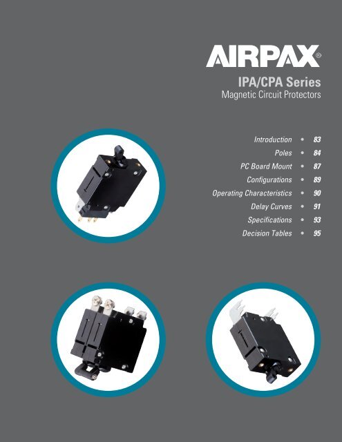
<strong>IPA</strong>/<strong>CPA</strong> <strong>Series</strong>Hydraulic Magnetic Circuit ProtectorsINTRODUCTIONThe <strong>Airpax</strong> <strong>IPA</strong>/<strong>CPA</strong> hydraulic-magnetic circuit protectorsprovide low-cost power switching, reliable circuit protectionand accurate circuit control for equipment in the internationalmarketplace.<strong>IPA</strong> models meet IEC spacing requirements that are mandatoryfor equipment which must comply with IEC specifications 601and 950 and VDE specifications 0804 and 0805. In addition, theyare UL Recognized as supplementary protectors per UL STD.1077, CSA Certified as supplementary protectors per CSA C 22.2-No. 235, TUV Approved to VDE 0642 (EN60934), CCC Approved(pending) and CE Compliant.Designed using the latest in sensitive hydraulic magnetictechnology, the <strong>IPA</strong> line adapts itself to many applications andenvironments. They’re ideal for data processing and businessmachines, medical instrumentation, broadcast equipment,vending and amusement machines, military applicationsand wherever precision operation is required. Temperaturedifferences which affect fuses and other thermal devices are nota concern.One important feature of this protector line is a “trip free” action,which means the circuit will trip in the presence of an overloadeven though the handle is held in the ON position. The delaymechanism senses the fault and the contacts open.The <strong>IPA</strong> is available in configurations including series and serieswith auxiliary switch, with a choice of delays and ratings in eitherDC, 50/60Hz or 400Hz versions. Single or multi-pole versionsare available, with a variety of pole arrangements to meet yourspecifications.83<strong>IPA</strong> <strong>Series</strong> - Introductionhttp://airpax.sensata.com
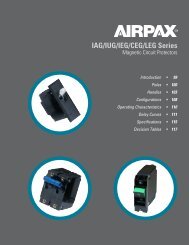
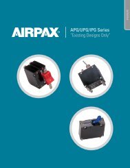
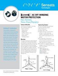
SINGLE POLE (ONE HANDLE)<strong>IPA</strong> <strong>Series</strong> (PCB Mount)LINE.635[16.13]Mounting Detail60.535[13.59]1.654[42.01].982[24.94]ONOFF1.260[32.00].551[14.00]1.260[32.00].787[19.99]1.732[43.99]1.988 MAX.[50.50].098[2.49]2X M3.165 MAX.[4.19].640 MAX.[16.26]2X .157[3.99].228[5.79]Notes:1. Tolerance ± .015 [.38] unless noted. Dimensions in brackets [ ] are millimeters.2. Main circuit breaker terminals are stationary male push-on type: .248 [6.30]wide x .031 [.787] thick x .474 [12.00] long, or screw type: M4 x .354 [8.99]wide x .031 [.787] thick x .474 [12.00] long.<strong>IPA</strong> <strong>Series</strong> - Poles 84
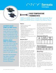
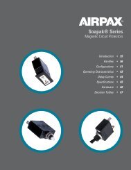
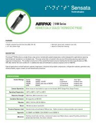
CONFIGURATIONS<strong>Series</strong> TripThe most popular configuration for magnetic protectorsis the series trip where the sensing coil and contacts are inseries with the load being protected. In addition to providingconventional overcurrent protection, the handle positionconveniently indicates circuit status.Auxiliary Switch (Applies to <strong>Series</strong> Trip Only)This is furnished as an integral part of a series pole insingle or multi-pole assemblies. Isolated electrically from theprotector’s circuit, the switch works in unison with the powercontacts and provides indication at a remote location of theprotector’s on-off status.Auxiliary switch contacts actuate simultaneously with themain breaker contacts, and will open regardless of whetherthe breaker contacts are opened manually or electrically. Forauxiliary switch ratings below 6Vac or 5Vdc, an auxiliaryswitch with gold contacts, designated as REG, is available.Gold contacts are not recommended for load current above100 milliamps. An optional auxiliary switch, RS, configurationallows an alarm or signal to be forwarded only upon electricaloverload, allowing for easier detection of fault circuit.TYPICAL RESISTANCE / IMPEDANCECurrent Ratings(Amps)1.383[35.13]<strong>Series</strong> Type (Except delays 40, 50, 60)DC(ohms)AC, 50/60Hz(ohms)AC, 400Hz(ohms)0.050 427 478 —0.100 100 103 204<strong>Series</strong> Trip0.250 19 20 340.500 4.6 6.3 8.20.750 2.04 2.06 3.521.00 0.91 0.92 1.862.50 0.17 0.19 0.285.00 0.045 0.046 0.0737.50 0.018 0.019 0.037.135[3.43] 10.0 0.013 0.014 0.02015.0 0.0072 0.0073 0.0109LINELINE20.0 0.005 0.0051 —25.0 0.003 0.0035 —DCR and Impedance values are based on measurements by the voltmeterammeter LOAD method. LOAD Rated current is applied for one hour and at a voltage notless than 20 volts. Ambient temperature: 25 C; Tolerance: Below 10 amps ±25%; Switch Above 10 <strong>Series</strong> amps ± 50%; *Consult factory for special values and for coilimpedance of delays not shown.<strong>Series</strong> Trip<strong>Series</strong> with Auxiliary Switch1.383[35.13].729 MAX.[18.52].369[9.37].377[9.58]LINE.135[3.43]1.383[35.13]1.015[25.77].775[19.68]CNONC1.024[26.00]LINELINELINELINELINELOADLOADCCCSwitch<strong>Series</strong>NONCLOADNONCLOADNONCLOADNotes:1. Main circuit protector terminals are stationary male push-on type: .248 [6.30]wide x .031 [.787] thick x .474 [12.00] long, or screw type: M4 x .354 [8.99]<strong>Series</strong> wide x with .031 [.787] Auxiliary thick Switch x .474 [12.00] long.2. Auxiliary switch terminals are: .110 [2.79] wide x .020 [0.51]thick x .343 [8.71] long..729 MAX..3773. [18.52] Tolerance ± .015 [.38] unless noted. Dimensions in brackets [ ] are [9.58] millimeters.C-NC = Breaker in“OFF” position.<strong>Series</strong> withAuxiliary SwitchBreaker in “ON” or manuallyturned “OFF” position.Breaker in electrically tripped“OFF” position.Auxiliary AlarmSwitch (IRS4, IRSG4)89.369[9.37]LINE<strong>IPA</strong> <strong>Series</strong> - ConfigurationsChttp://airpax.sensata.com
<strong>IPA</strong> <strong>Series</strong> (PCB Mount)RECOMMENDED TORQUE SPECIFICATIONSComponentTorque (in-lbs)6-32 Mounting Inserts 6 to 8M3 Mounting Screws 4 to 5M4 Terminal Screws 10 to 12Where applicable, mechanical support must be provide to theterminals when applying torqueAPPROXIMATE WEIGHT PER POLEOuncesGrams1.7 48INRUSH PULSE TOLERANCEDelayPulse Tolerance61, 62, 600 8 times rated current61F, 62F, 600F 12 times rated currentComparison of inrush pulse tolerance is with and without theinertia delay feature for each of the 50/60 Hz delays. Pulsetolerance is defined as a single pulse of half sine wave peakcurrent amplitude of 8 milliseconds duration that will not tripthe circuit protector.<strong>IPA</strong> <strong>Series</strong> - Specifications 94
HOW TO ORDERThe ordering code for <strong>IPA</strong>/<strong>CPA</strong> protectors may bedetermined by following the steps in the decisiontables shown here.1<strong>IPA</strong><strong>IPA</strong>P<strong>IPA</strong>H<strong>IPA</strong>HP<strong>CPA</strong><strong>CPA</strong>HFirst DecisionTypeOne toggle handle per unitUL RecognizedOne toggle handle per unitUL RecognizedPC board mountOne toggle handle per poleUL RecognizedOne toggle handle per poleUL RecognizedPC board mountOne toggle handle per unitUL Listed per UL489AOne toggle handle per poleUL Listed per UL489A2-1-11-111-6-66-666Second DecisionPolesSingle pole w/ quick connect terminals or PC board if P is used.Two pole w/ quick connect terminals or PC board if P is used.Three pole w/ quick connect terminals or PC board if P is used.Single pole w/ screw terminalsTwo pole w/ screw terminalsThree pole w/ screw terminalsNote:A The coding given permits a self-assigning part number. Other configurations may require afactory assigned part number. Typical examples are units with mixed ratings, combinations ofstyles or construction. With these, it is suggested that order entry be by description and/ordrawings and a part number will be assigned. Additionally, it is a standard policy to establish afactory assigned part number wherever a descriptive drawing exits to provide cross reference,traceability and manufacturing control.95<strong>IPA</strong> <strong>Series</strong> - Decision Tableshttp://airpax.sensata.com
Example:<strong>IPA</strong>P -1 -1REC4 - 61- 10.0 - L - 01 - T1 2 3 4 5 6 7 8<strong>IPA</strong> <strong>Series</strong> (PCB Mount)3-0-1-1REC4Third DecisionConfigurations-1REG4-1RS4-1RSG4Switch only<strong>Series</strong><strong>Series</strong> with silver contactAuxiliary switch<strong>Series</strong> with gold contactAuxiliary switch<strong>Series</strong> with silver contactAlarm switch<strong>Series</strong> with gold contactAlarm switchNotes: 1. For switch type, eliminate 4th & 5th decision.2. Switch will be marked with Max. current & voltage.3. The alarm switch is located in the handle pole forsingle handle types and in pole 2 for units with ahandle per pole. The auxilliary switch may be locatedin any pole. However the standard location is in pole 2.4. Switch type with alarm switch must be multi-poleconnected to a pole equipped with either anovercurrent or overvoltage mechanism.(Consult factory for further information.)4 Fourth DecisionFrequency & DelaySW Switch only56A-L-R-S-Fifth DecisionRated CurrentUse three numbers to specify requiredvalue within ranges described below.Rating0.50 to 30.0*Notes: 1. On multi-pole units, the poles are numbered left toright when viewed from terminal end.2. *15 amps maximum at 400HzSixth Decision (Optional)Mounting & Terminal TypeMetric M3 mounting inserts andif screw terminals M4.PC board mounting plate &terminals, 90 facing leftPC board mounting plate &terminals, 90 facing rightPC board terminals, rear facingwith front panel insert mount.Note: Right and Left determined with breaker viewed fromthe rear, in normal vertical mounted position. (see pages 70 & 71)-40400Hz instant trip-41-42-400-50400Hz short delay400Hz long delay400Hz motor startDC instant trip*701Seventh DecisionHandle ColorBlack with I/O markings-51DC short delay*-52-500-60-61-62-600DC long delay*DC motor start50/60Hz instant trip50/60Hz short delay50/60Hz long delay50/60Hz motor start8TCEighth Decision (Optional)Agency ApprovalTÜV*CCCNotes: 1. *25 amperes max rated current for TÜV approval.2. CCC Approval is pending.Note: For addition of inertial delay, add an “F” to anydelay numeral. (Example: 62F)*<strong>CPA</strong> types are only available with DC ratings.<strong>IPA</strong> <strong>Series</strong> - Decision Tables 96
©2013 <strong>Sensata</strong> Technologies, Inc. All rights reserved worldwide. The following data sheet is an excerpt from our <strong>Airpax</strong> PowerProtection Catalog, Literature # 2455005000, printed in the USA, May 9th, 2013.Important Notice: <strong>Sensata</strong> Technologies reserves the right to make changes to, or to discontinue, any product or service identified inthis publication without notice. Before placing orders, users should obtain the latest version of the relevant information to verify thatthe information being relied upon is current.<strong>Sensata</strong> Technologies assumes no responsibility for customers’ product designs or applications. Users must determine the suitabilityof the <strong>Sensata</strong> device described in this publication for their application, including the level of reliability required. Many factors beyond<strong>Sensata</strong>’s control can affect the use and performance of a <strong>Sensata</strong> product in a particular application, including the conditions underwhich the product is used and the time and environmental conditions in which the product is expected to perform. As these factorsare uniquely within the user’s knowledge and control, it is essential that the user evaluate the <strong>Sensata</strong> product to determine whether itis fit for a particular purpose and suitable for the user’s application.<strong>Sensata</strong> Technologies products are sold subject to <strong>Sensata</strong>’s Terms and Conditions of Sale which can be found at:www.sensata.com/terms.htm<strong>Sensata</strong> Technologies Inc.529 Pleasant StreetAttleboro, MA 02703, USAPhone: +1 508-236-3287http://airpax.sensata.com/