Forest Engineering – Timber Preparation - Sappi
Forest Engineering – Timber Preparation - Sappi
Forest Engineering – Timber Preparation - Sappi

You also want an ePaper? Increase the reach of your titles
YUMPU automatically turns print PDFs into web optimized ePapers that Google loves.
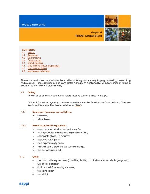
forest engineering<br />
CONTENTS<br />
4.1 Felling<br />
4.2 Debarking<br />
4.3 Debranching<br />
4.4 Cross-cutting<br />
4.5 Infield stacking<br />
4.6 Mechanised timber preparation<br />
4.7 Mechanised felling<br />
4.8 Mechanical debarking<br />
<strong>Timber</strong> preparation normally includes the activities of felling, debranching, topping, debarking, cross-cutting<br />
and stacking. These activities can be done motor-manually or mechanically. A major portion of felling in<br />
South Africa is still done motor-manually.<br />
4.1 Felling<br />
As with all other forestry operations, fellers must be suitably trained for the job.<br />
Further information regarding chainsaw operations can be found in the South African Chainsaw<br />
Safety and Operating Handbook published by FESA.<br />
4.1.1 Equipment for motor-manual felling:<br />
� chainsaw;<br />
� felling lever.<br />
4.1.2 Personal protective equipment:<br />
� approved hard hat with visor and earmuffs;<br />
� brightly coloured T-shirt and/or high visibility vest;<br />
� appropriate gloves <strong>–</strong> if required;<br />
� approved cutter pants;<br />
� steel capped safety boots;<br />
� First Aid kit and pressure pad (bomb bandage),<br />
� rain suit when required.<br />
chapter 4<br />
timber preparation<br />
4.1.3 Other:<br />
� tool pouch with required tools (round file, flat file, combination spanner, depth gauge tool);<br />
� fuel and oil container;<br />
� cloth or brush for cleaning purposes;<br />
� fire extinguisher;<br />
� first aid kit.<br />
6
forest engineering<br />
chapter 4: timber preparation<br />
4.1.4 Felling technique:<br />
� Ensure that no other person is within the felling danger zone of at least two tree lengths<br />
radius from the tree to be felled. The danger zone is 360° around the tree to be felled.<br />
� Determine an appropriate escape route. Normally 45° away from the felling direction.<br />
� Ensure the escape route is open and clear of obstacles.<br />
The following schematic drawing shows the danger zone and the escape route around the tree<br />
to be felled (see Figure 4.1).<br />
Felling direction<br />
Two tree length radius<br />
Check the possible felling direction by taking into account the following:<br />
� the angle at which the tree is leaning;<br />
� crown size and overhang;<br />
� neighbouring trees;<br />
� wind direction;<br />
� planned extraction direction;<br />
� slope on which the tree is growing;<br />
� environmental considerations;<br />
� silvicultural requirements.<br />
Fell the tree using the following three cuts:<br />
� directional notch (top cut);<br />
� directional notch (undercut) - angle to be at least 45°;<br />
� felling cut.<br />
Escape route<br />
Figure 4.1: Schematic representation of felling danger zone and escape route.<br />
The tree is steered in the desired direction by creating a felling hinge. Figure 4.2 below shows<br />
the three felling cuts.<br />
7
forest engineering<br />
Felling cut<br />
Hinge<br />
chapter 4: timber preparation<br />
Felling direction<br />
Figure 4.2: Schematic representation of felling cuts.<br />
Directional notch<br />
4.1.5 Felling production<br />
Felling operations are normally controlled by giving a pre-determined minimum production (task)<br />
level.<br />
The following factors could influence felling productivity:<br />
� safety considerations;<br />
� tree size;<br />
� tree diameter;<br />
� espacement;<br />
� terrain;<br />
� tree species;<br />
� debarking percentage (where applicable);<br />
� stem form;<br />
� crown shape and size;<br />
� lean of the tree;<br />
� felling direction;<br />
� undergrowth;<br />
� serviceability and suitability of equipment;<br />
� operator skills;<br />
� cutter working alone or with an assistant;<br />
� subsequent operations to be completed by the operator and assistant (where applicable);<br />
� environmental considerations; and<br />
8
forest engineering<br />
� silvicultural considerations.<br />
chapter 4: timber preparation<br />
The production levels for Eucalyptus and Acacia felling, debarking and stacking, which are<br />
given in Annexure “B”, are based on the following task descriptions:<br />
� The cutter and an assistant are responsible for felling, cross-cutting, debranching and<br />
stacking of brushwood.<br />
� The debarkers are responsible for debarking the logs.<br />
� The stackers are required to build stacks for further extraction or transport.<br />
Guidelines for task determination for Eucalyptus grandis can be found in Annexure “A”, and<br />
tasking guidelines for pine species can be found in Annexure “C”.<br />
4.2 Debarking<br />
Debarking is the process of removing the bark from Eucalyptus and Acacia species after felling. This<br />
can be done manually or mechanically.<br />
4.2.1 Manual debarking<br />
Manual debarking is normally performed with a sharpened hatchet. The bark is detached either<br />
as long or short strips or small plates. As far as possible, effort should be made to ensure that<br />
logs are free of cambium.<br />
Debarking spuds (hoe type piece of equipment) and shaped spades can also be used to<br />
debark. Either tree lengths or logs can be debarked.<br />
4.2.2 The following is seen as the minimum protective clothing that must be worn by manual<br />
debarkers:<br />
� overalls;<br />
� hard hat;<br />
� safety boots;<br />
� leg protectors;<br />
� rubber gloves;<br />
� eye protection.<br />
Manual debarking is a strenuous job with an awkward posture and debarkers must be trained in<br />
the correct debarking techniques.<br />
4.2.3 Debarkers must take note of the following:<br />
� Always debark on the far side of the log away from feet and legs.<br />
� Always use a properly maintained debarking tool.<br />
� Always chip away from yourself.<br />
� Do not walk or stand on wet logs.<br />
9
forest engineering<br />
chapter 4: timber preparation<br />
4.2.4 Debarking percentage<br />
Debarking percentage is the term used to express the ease of removing the bark from freshly<br />
felled Eucalyptus and Acacia species. It is the percentage of cleanly debarked logs in a total<br />
number of debarked logs.<br />
Debarking % = (number of cleanly debarked logs ÷ total number of logs sampled) x 100<br />
Cleanly debarked logs are logs where no cambium or less than 30% cambium remains on the<br />
log. Chiselled or shaved logs are where more than 30% cambium remains and the bark has to<br />
be chiselled off in small pieces. See Photo 4.1 and 4.2 below:<br />
Photo 4.1 (left): Cleanly stripped log. 1<br />
Photo 4.2 (right): Chiselled log. 1<br />
Debarking is expressed in classes as shown in the following table. Note that the table gives the<br />
debarking class, the corresponding debarking percentage and the debarking percentage as you<br />
will find it in the tasking sheets in the annexures.<br />
Debarking class Debarking % Task Table<br />
1 0 -40 40%<br />
2 41 <strong>–</strong> 55 50%<br />
3 56 <strong>–</strong> 75 60% - 70%<br />
4 76 <strong>–</strong> 85 80%<br />
5 86 - 100 90%<br />
Table 4.1: Debarking classes.<br />
Rip-stripping is a term used where the debarkers rip the bark off in long strips from standing<br />
trees. This practice is only viable when trees are debarking well. Debarkers should be on the<br />
lookout for falling branches and premature breaking of the bark when rip-stripping.<br />
1<br />
10
forest engineering<br />
Photo 4.3: Ripped stripped trees. 1<br />
The stripability percentage can be influenced by the following factors:<br />
� species;<br />
� growing site;<br />
� season of stripping;<br />
� time of day;<br />
� temperature;<br />
� time after felling; and<br />
� whether the trees are stressed (drought, disease) or not.<br />
chapter 4: timber preparation<br />
Debarking tasking tables are presented for Eucalypts grandis, Eucalyptus macarthurii,<br />
Eucalyptus smithii as well as Acacia mearnsii.<br />
4.2.5 Preparing wattle bark<br />
Wattle bark is normally stacked in bundles of approximately 40cm x 40cm x 231 or 240cm. Thin<br />
strips of bark are used to tie the bundle.<br />
Bundle size is determined by the specifications of the receiving bark mill. Bark bundles vary in<br />
mass from 25kg to 40kg per bundle. Photo 4.4 below is an example of a bark bundle being<br />
prepared.<br />
11
forest engineering<br />
Photo 4.4: Preparing a bark bundle. 1<br />
Bark thickness is an important factor as mills pay a premium for thicker bark.<br />
chapter 4: timber preparation<br />
The tables in Annexure “E” 2 give an indication of bark mass and volume for different bark<br />
thicknesses.<br />
4.3 Debranching<br />
Debranching is the process of removing the branches from felled trees.<br />
4.3.1 When debranching by axe the following should be noted:<br />
� Work from the butt-end of the tree towards the top.<br />
� Always debranch from the far side of the log.<br />
� Axe strokes should be with the angle of the branch and not against it.<br />
� Only debranch merchandisable timber. Do not waste effort to debranch above the<br />
minimum diameter mark.<br />
� Debranchers should be outside the danger zone of two tree lengths from felling<br />
operations. 3<br />
Debranching by chainsaw is the preferred method to remove branches. There are mainly two<br />
different methods to approach debranching, namely the six point lever method and the sweep<br />
method. 4 See Figure 4.3 and 4.4.<br />
4.3.2 Irrespective of which method is used, the following basic rules should be observed:<br />
� Work at a comfortable height and try to avoid bending over. This can be achieved by<br />
planning ahead and by correct felling. Use already felled trees, rocks or the terrain to<br />
create a comfortable working height.<br />
� Get a firm foothold and work with the chainsaw close to your body.<br />
� Flex your knees and not your back.<br />
� Do not move your feet when you are sawing on the same side of the tree as you are<br />
standing.<br />
12
forest engineering<br />
� The weight of the saw should be against the tree and not your leg.<br />
� Lead with your left leg when starting to debranch.<br />
Figure 4.3 (left): Six point lever method of debranching.<br />
Figure 4.4 (right): Sweep method of debranching.<br />
chapter 4: timber preparation<br />
4.4 Cross-cutting<br />
Cross-cutting is the process whereby felled trees are cut into marketable lengths infield or at landings.<br />
It is important to use the correct technique when cross-cutting. Using the wrong technique can cause<br />
accidents, pinching of the saw or splitting of the log.<br />
4.4.1 Observe the following when cross-cutting:<br />
� Determine the stresses the stem is under, example upward, downward or sideways.<br />
� Observe carefully how the timber reacts to being sawn.<br />
� Be aware of where you are standing when you cross-cut.<br />
� Stand off to one side instead of right in front of the cut.<br />
� When cross-cutting stems with sideways tension one must always stand on the inside of<br />
the curve when cutting.<br />
Figure 4.5, 4.6 and 4.7 demonstrate the cutting technique for the most common tensions a stem<br />
can be subjected to. 3<br />
13
forest engineering<br />
Figure 4.5: Stem with downward tension.<br />
Method to use:<br />
1. Start by making a cut downwards until the cut begins to pinch the guidebar.<br />
2. Continue the cut from the bottom upwards. Try to make the two cuts meet.<br />
Figure 4.6: Stem with upward tension.<br />
chapter 4: timber preparation<br />
Method to use:<br />
1. Start by making a cut upwards until the cut begins to pinch the guidebar.<br />
2. Continue the cut from the top side downwards. Try to make the two cuts meet.<br />
14
forest engineering<br />
Figure 4.7: Stem under sideways tension.<br />
chapter 4: timber preparation<br />
Method to use:<br />
1. Cut an open directional wedge on the inside or non-stressed side of the stem.<br />
2. Start at the top and saw in stages until the stem breaks.<br />
3. Remember to always stand on the inside or non-stressed side of the stem.<br />
Guidelines for cross-cutting can be found in Annexure “F”.<br />
4.5 Infield stacking<br />
Infield stacking is the process whereby logs are grouped infield for further loading. The size of the<br />
stack is determined by the available volume, the log size and the loading method that will be used.<br />
Stacking can be done by hand or mechanically. As excessive infield disturbance of the soil is not<br />
good practice, mechanical stacking by 3-wheeler should be minimised where possible.<br />
Stackers should always ensure that the stacking area is free of bark, branches or other debris.<br />
Building the stack on bearers will ensure that minimum debris is picked up at loading.<br />
4.5.1 Stacking productivity and quality may be influenced by the following factors:<br />
� safety considerations;<br />
� log length;<br />
� piece size and mass;<br />
� available volume per hectare;<br />
� terrain conditions;<br />
� stacking area;<br />
� stacking method; and<br />
� machinery employed.<br />
Positioning of the stack is an important element. If the stack is positioned in between stumps<br />
or standing trees, it could negatively affect the loading of the timber. The stack must be<br />
15
forest engineering<br />
chapter 4: timber preparation<br />
created in such a position that the section of the stack at the point where the grab of the<br />
loading machine secures the logs is free of all obstacles.<br />
All stackers should be issued with logging tongs and should be trained in the proper use of<br />
them.<br />
Photo 4.5: Logging tongs.<br />
4.5.2 Stack types<br />
Depending on the terrain, stacking method, piece size and loading method, there are different<br />
types of stacks that can be constructed.<br />
4.5.3 Rough-lining of timber<br />
In this method the timber is just turned so that it all faces the same direction. The timber is<br />
normally not stacked but lies on long roughly aligned rows. See Photo 4.6.<br />
Photo 4.6: Roughlined timber.<br />
16
forest engineering<br />
chapter 4: timber preparation<br />
4.5.4 Classic stack<br />
This type of stack is constructed by laying down two bearer logs approximately 2m apart.<br />
Uprights are hit into the ground to support the stacked timber. Depending on the loading<br />
and/or extraction method, stack size may vary anything from 2 to 5 tons per stack. See<br />
Photo 4.7.<br />
Photo 4.7: Classic stack.<br />
4.5.5 Diamond stack<br />
This type of stack does not require any uprights to be driven into the ground for support. The<br />
stack is built to supply its own support. This type of stack works well in flat areas. See<br />
Photo 4.8.<br />
Photo 4.8: Diamond stack.<br />
17
forest engineering<br />
chapter 4: timber preparation<br />
4.5.6 Stacking production<br />
Stacking production is a function of the log size (length and volume), available volume, terrain<br />
and the type of stack to be built. Task tables for stacking of Eucalyptus are given in<br />
Annexure “D”. These tasks are based on building a classic stack.<br />
4.6. Mechanised timber preparation<br />
Mechanised timber preparation is gaining acceptance throughout our industry. Various equipment<br />
manufacturers are actively importing harvesting machines and related equipment.<br />
The mechanised timber preparation system can be classified into semi-mechanised and fullymechanised<br />
systems. See flowchart below.<br />
Semimechanised<br />
Mechanised<br />
harvesting<br />
Fully<br />
mechanised<br />
Wheeled based Tracked base Cut to length Multi stem<br />
Wheeled<br />
leveling / nonleveling<br />
Purpose built Hybrid Wheeled<br />
Tracked<br />
leveling / nonleveling<br />
Wheeled<br />
leveling / nonleveling<br />
Tracked<br />
leveling / nonleveling<br />
Figure 4.8: Classification of mechanized harvesting systems.<br />
Semi mechanised systems are defined as a combination of motor-manual felling and mechanical<br />
debarking or further processing. The debarking, for example, can be done by a debarking head or<br />
other mechanical means like flail debarkers. Photo 4.9 shows a locally developed debarking head<br />
and Photo 4.10 a small flail debarker.<br />
18
forest engineering<br />
Photo 4.9: Locally designed debarking head.<br />
Photo 4.10: Locally manufactured flail debarker.<br />
chapter 4: timber preparation<br />
Fully mechanised systems are systems where the felling and further conversion of the tree is done by<br />
fully mechanical means. The full mechanical system can further be categorised as Cut to Length (CTL)<br />
or multi stem systems.<br />
19
forest engineering<br />
chapter 4: timber preparation<br />
CTL systems normally use equipment that can process one tree at a time. The tree is felled,<br />
debranched, debarked (where applicable) and cross-cut into lengths and deposited ready for loading by<br />
one machine. See Photo 4.11.<br />
CTL systems can furthermore be classified into so-called hybrid systems or purpose built systems. The<br />
hybrid systems are set up utilising an excavator or other suitable carrier together with a harvesting<br />
head.<br />
Purpose built systems are specifically designed to perform a harvesting function.<br />
Photo 4.11: Tracked single stem harvester (CTL system).<br />
Multi stem systems can process more than one stem at a time. See Photo 4.12. The multi stem system<br />
normally uses a felling and bunching piece of equipment, an extraction piece of equipment, a cross-cut<br />
or debarking system or even a chipping system.<br />
Photo 4.12: Equipment used in a multi stem harvesting system (feller buncher, grapple skidder,<br />
slasher deck).<br />
4.7 Mechanised felling<br />
Mechanised felling has the following advantages over motor manual felling:<br />
� Increased safety of the felling operation.<br />
� Increased felling production and productivity.<br />
� Improved downstream extraction activities due to improved directional felling and<br />
bunching.<br />
20
forest engineering<br />
� Multi shift felling allows for better equipment utilization.<br />
The following factors could influence mechanised felling productivity:<br />
� safety considerations;<br />
� tree species;<br />
� tree size;<br />
� tree diameter;<br />
� espacement;<br />
� terrain;<br />
� underfoot conditions;<br />
� debarking percentage (where applicable);<br />
� stem form;<br />
� crown shape and size;<br />
� number and size of branches;<br />
� equipment type; and<br />
� operator competence.<br />
chapter 4: timber preparation<br />
Mechanical felling heads use either a shear or a non-shear function to cut through a tree.<br />
Shears cut through a tree like scissors. See Photo 4.13. Non-shear disks cut through the tree using<br />
either a rotating disk or a bar and chain. See Photo 4.14.<br />
Photo 4.13 (left): Shear type felling head. 5<br />
Photo 4.14 (right): Felling head utilizing bar and chain. 1<br />
4.8 Mechanical debarking<br />
There are various types of mechanical debarking heads on the market. They all work on the principle<br />
of grooved rollers rotating the stem under pressure, which causes the bark to be stripped off as the<br />
stem passes through the rollers. Cutting knives shear off the branches in front of the rollers (see<br />
Photo 4.15).<br />
21
forest engineering<br />
chapter 4: timber preparation<br />
As with manual debarking there are various factors that could influence the debarking production and<br />
quality. Such factors include:<br />
� species;<br />
� roller feed speed;<br />
� roller pressure;<br />
� tree form;<br />
� number and size of branches;<br />
� operator competence; and<br />
� terrain.<br />
1 Photos by A. Immelman.<br />
Photo 4.15: Felling/debarking head. 1<br />
Photo 4.16 (left): Mechanically debarked timber. 1<br />
Photo 4.17 (right): <strong>Timber</strong> presentation from mechanical felling, debarking and cross-cutting. 1<br />
22
forest engineering<br />
2<br />
Tables taken from De La Borde’s <strong>Timber</strong> Harvesting Manual <strong>–</strong> 1992.<br />
3<br />
Zaremba - 1976.<br />
4<br />
Husqvarna undated.<br />
5<br />
Photo by G. van Huysteen.<br />
chapter 4: timber preparation<br />
23