GT tanks
GT tanks
GT tanks
- No tags were found...

You also want an ePaper? Increase the reach of your titles
YUMPU automatically turns print PDFs into web optimized ePapers that Google loves.
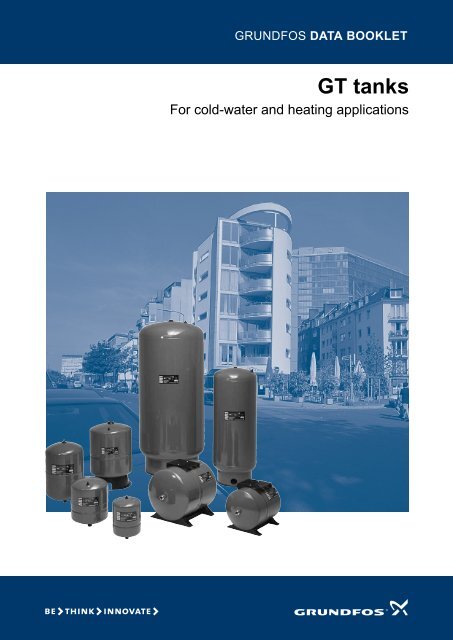
GRUNDFOS DATA BOOKLET<strong>GT</strong> <strong>tanks</strong>For cold-water and heating applications
<strong>GT</strong> <strong>tanks</strong>Contents1. General data 3Applications 3Type key 3Tank range 3Overview of tank types 3Approvals and markings 3Tank colours 3Operating conditions 4Material specifications 42. Cold water 5Cold-water <strong>tanks</strong> 5Tank range 5Sizing 7<strong>GT</strong>-U, 10 bar 8<strong>GT</strong>-U, 16 bar 9<strong>GT</strong>-U, 25 bar 10<strong>GT</strong>-H, 10 bar 11<strong>GT</strong>-H, 16 bar 12<strong>GT</strong>-H, 10 bar 13<strong>GT</strong>-D, 10 bar, <strong>GT</strong>-DF, 8.6 bar 14<strong>GT</strong>-C, <strong>GT</strong>-CF, 8.6 bar 153. Heating 16Applications 16Tank range 16Sizing 16<strong>GT</strong>-HR, 6 bar 174. Further product documentation 18WebCAPS 18WinCAPS 192
<strong>GT</strong> <strong>tanks</strong>11. General dataApplicationsThe Grundfos <strong>GT</strong> pressure <strong>tanks</strong> are long-life <strong>tanks</strong>ideally suited for controlling the pressure in domestic aswell as industrial applications in the following systems:• cold-water (drinking-water) systems.See Cold-water <strong>tanks</strong>, page 5.• heating systems. See 3. Heating, page 16.Grundfos <strong>GT</strong> <strong>tanks</strong> ensure long, maintenance-free,reliable and controlled operation.<strong>GT</strong> <strong>tanks</strong> can be integrated in many different systemswith a wide variety of pumps. The large number of <strong>tanks</strong>izes and types available makes it possible to select thepressure tank that best suits the application and systemin question.Type keyExample <strong>GT</strong> - U - 25 PN 10 G 1/2 VType rangeTank type:U = bladderH = diaphragmD = double diaphragmDF = double diaphragm with FlowThruC = composite tankCF = composite tank with FlowThruHR = non-replaceable diaphragm forheating applicationsTank volume [litres]Pressure ratingPipe connectionPosition:V =verticalH = horizontalTank rangeApplication Positioning Volume range [l]Vertical 8 to 5000Cold waterHorizontal 24 to 80Heating Vertical 8 to 1000Overview of tank typesThe table below shows the available tank types inrelation to application.Symbol Description● Recommended- Not recommendedTank typeApplication<strong>GT</strong>-U <strong>GT</strong>-H <strong>GT</strong>-D <strong>GT</strong>-DF <strong>GT</strong>-C <strong>GT</strong>-CF <strong>GT</strong>-HRHeating - - - - - - ●Chilled water - - - - - - ●Sea water - - - - ● - -Grey water* ❍ ● ● - ● - -Drinking water ❍ ❍ ❍ ❍ ❍ ● -* Grey water, also known as sullage, is non-industrial wastewatergenerated from domestic processes, such as dish washing, laundryand bathing.Approvals and markingsApprovalsMarkingsTank typeWRAS NSF ACS CE GOST<strong>GT</strong>-U - - ● ● -<strong>GT</strong>-H - - ● ● ●<strong>GT</strong>-D - - ● ● ●<strong>GT</strong>-DF - - ● ● ●<strong>GT</strong>-C - - ● ● ●<strong>GT</strong>-CF - - ● ● ●<strong>GT</strong>-HR - - - ● -Tank coloursApplication Colour Colour codeCold water Grey NCS S7005-R80B, gloss 20-35Heating Red RAL3011General data3
1<strong>GT</strong> <strong>tanks</strong>General dataOperating conditionsMaximum operating pressure25 bar <strong>GT</strong>-U bladder tank<strong>GT</strong>-U bladder tank16 bar<strong>GT</strong>-H diaphragm tank<strong>GT</strong>-U bladder tank10 bar <strong>GT</strong>-D double-diaphragm tank<strong>GT</strong>-H diaphragm tank<strong>GT</strong>-DF double-diaphragm tank with FlowThru8.6 bar <strong>GT</strong>-CF composite tank with FlowThru<strong>GT</strong>-C composite tank6 bar <strong>GT</strong>-HR heating tank (5 to 1000 litres)10 °C 20 °C 30 °C 40 °C 50 °C 60 °C 70 °C 80 °C 90 °C 100 °CMaximum liquid temperatureMaterial specificationsPos. Component Material Tank type1 Tank bodyLow-carbon sheet steel<strong>GT</strong>-U, <strong>GT</strong>-H, <strong>GT</strong>-D, <strong>GT</strong>-DF, <strong>GT</strong>-HRFibreglass, epoxy resin, composite<strong>GT</strong>-C, <strong>GT</strong>-CA, <strong>GT</strong>-CF2 Bladder, diaphragmButyl<strong>GT</strong>-U, <strong>GT</strong>-H, <strong>GT</strong>-D, <strong>GT</strong>-DF, <strong>GT</strong>-C, <strong>GT</strong>-CFEPDM rubber<strong>GT</strong>-HRStainless steel EN 1.4301/AISI 304<strong>GT</strong>-H, <strong>GT</strong>-D, <strong>GT</strong>-DF3 Flange/pipe connectionStainless steel EN 1.4401/AISI 316 Ti<strong>GT</strong>-UPolyvinyl chloride (PVC)<strong>GT</strong>-C, <strong>GT</strong>-CFLow-carbon sheet steel<strong>GT</strong>-HR4 Air valve Steel/brass <strong>GT</strong>-U, <strong>GT</strong>-H, <strong>GT</strong>-D, <strong>GT</strong>-DF, <strong>GT</strong>-C, <strong>GT</strong>-CF, <strong>GT</strong>-HR5 Clamping ring/feetLow-carbon sheet steel<strong>GT</strong>-U, <strong>GT</strong>-H, <strong>GT</strong>-D, <strong>GT</strong>-DF, <strong>GT</strong>-HRPolypropylene (PP)<strong>GT</strong>-C, <strong>GT</strong>-CF6 Lifting eye/skirtLow-carbon sheet steel<strong>GT</strong>-U, <strong>GT</strong>-H, <strong>GT</strong>-D, <strong>GT</strong>-DF, <strong>GT</strong>-HRPolypropylene (PP)<strong>GT</strong>-C, <strong>GT</strong>-CF7 Tapped hole Low-carbon sheet steel <strong>GT</strong>-U<strong>GT</strong>-U<strong>GT</strong>-H7<strong>GT</strong>-HR644112235563TM03 8262 0907 - TM02 9095 0907 - TM03 1677 2705Fig. 1Sectional drawings, examples of <strong>tanks</strong>The actual <strong>GT</strong> tank may look different from the examples shown above.4
2<strong>GT</strong> <strong>tanks</strong>Cold water<strong>GT</strong>-CF (composite tank with FlowThru)The FlowThru connection diverts system water into andmore importantly out of the tank while the pump isrunning. This constant flushing ensures that the waterin the tank remains fresh and eliminates the risk ofstagnant water during normal system operation.See figs 2 and 3.Fig. 2Illustration of the FlowThru functionTM04 5424 3309TM04 5422 3309Fig. 3Illustration of the FlowThru principle6
2<strong>GT</strong> <strong>tanks</strong>Cold water<strong>GT</strong>-U, 25 barVertical installation, maximum pressure 25 bar, pre-charge pressure 4 barDimensions, weights and product numbers8 litres 80 to 800 litres1000 to 3000 litresDDDCHHH1CHH1CTM03 1681 2809 - TM03 8257 2809 - TM03 8258 2809Fig. 8Dimensional sketchesTank typeSize[l]Dimensions[mm]D H H1 CGross weight[kg]ReplaceablebladderStainless-steelflangeProduct numberCoated flange<strong>GT</strong>-U-8 PN 25 G 3/4 V 8 206 320 - G 3/4 8 - 96573347 -<strong>GT</strong>-U-80 PN 25 DN 50 V 80 450 925 185 DN 50 107 ● - 96603459<strong>GT</strong>-U-120 PN 25 DN 50 V 120 450 1235 185 DN 50 142 ● - 96603460<strong>GT</strong>-U-180 PN 25 DN 50 V 180 450 1515 185 DN 50 179 ● - 96603462<strong>GT</strong>-U-300 PN 25 DN 50 V 300 750 1275 200 DN 50 201 ● - 96603463<strong>GT</strong>-U-400 PN 25 DN 50 V 400 750 1395 200 DN 50 302 ● - 96603465<strong>GT</strong>-U-600 PN 25 DN 50 V 600 750 1860 185 DN 50 404 ● - 96603466<strong>GT</strong>-U-800 PN 25 DN 50 V 800 750 2260 185 DN 50 150 ● - 96603468<strong>GT</strong>-U-1000 PN 25 DN 50 V 1000 750 2760 185 DN 50 559 ● - 96603469<strong>GT</strong>-U-1500 PN 25 DN 65 V 1500 1200 2050 285 DN 65 911 ● - 96967953<strong>GT</strong>-U-2000 PN 25 DN 65 V 2000 1200 2500 285 DN 65 1184 ● - 96967955<strong>GT</strong>-U-3000 PN 25 DN 65 V 3000 1500 2520 315 DN 65 1632 ● - 96967957Note: For some <strong>GT</strong>-U <strong>tanks</strong>, the bladder is available as a spare part. The part number can be found on Grundfos.com (WebCAPS).10
2<strong>GT</strong> <strong>tanks</strong>Cold water<strong>GT</strong>-H, 16 barVertical installationDimensions, weights and product numbers8 to 35 litres 60 to 80 litresHDCHDCTM02 9086 2809 - TM02 9087 2809Fig. 10 Dimensional sketchesTank typeSize[l]Dimensions[mm]D H CGross weight[kg]Product number<strong>GT</strong>-H-8 PN 16 G 3/4 V 8 203 311 G 3/4 2.6 96528356<strong>GT</strong>-H-12 PN 16 G 3/4 V 12 229 364 G 3/4 3.1 96528357<strong>GT</strong>-H-18 PN 16 G 1 V 18 279 366 G 1 5.0 96528358<strong>GT</strong>-H-24 PN 16 G 1 V 24 290 445 G 1 5.1 96528360<strong>GT</strong>-H-35 PN 16 G 1 V 35 318 481 G 1 7.5 96528361<strong>GT</strong>-H-60 PN 16 G 1 V 60 388 528 G 1 10 96528362<strong>GT</strong>-H-80 PN 16 G 1 V 80 388 626 G 1 16.7 9652836312
<strong>GT</strong> <strong>tanks</strong>2<strong>GT</strong>-H, 10 barHorizontal installationDimensions, weights and product numbersCold waterL4DSupporting bracketCB1B4L3L2L1ZBHB24 x ZB3TM02 9085 2809 - TM01 1611 1501Fig. 11 Dimensional sketchesTank typeSize[l]Dimensions[mm]D H B L1 L2 L3 L4 Z CGross weight[kg]Productnumber<strong>GT</strong>-H-24 PN 10 G 1 H 24 289 444 235 447 250 84 156 4 G 1 6.5 96528388<strong>GT</strong>-H-60 PN 10 G 1 H 60 414 528 342 532 299 102 199 4 G 1 12.8 96528389<strong>GT</strong>-H-80 PN 10 G 1 H 80 414 724 342 730 229 201 306 4 G 1 18.0 96528390Supporting bracketTank typeSize[l]Dimensions[mm]B1 B2 B3 B4 Z<strong>GT</strong>-H-24 PN 10 G 1/4 H 24 220 165 139 107 10<strong>GT</strong>-H-60 PN 10 G 1/4 H 60 220 165 139 107 9<strong>GT</strong>-H-80 PN 10 G 1 H 80 220 165 139 107 913
2<strong>GT</strong> <strong>tanks</strong>Cold water<strong>GT</strong>-D, 10 bar, <strong>GT</strong>-DF, 8.6 barVertical installationDimensions, weights and product numbers<strong>GT</strong>-D<strong>GT</strong>-DFHDCTM02 9087 2809 - TM04 5936 4409Fig. 12 Dimensional sketchesTank typeSize[l]Dimensions[mm]D H CGross weight[kg]Product number<strong>GT</strong>-D<strong>GT</strong>-D-60 PN 10 G 1 V 60 406 571 G 1 13.5 96748301<strong>GT</strong>-D-80 PN 10 G 1 V 80 388 787 G 1 18.0 96528342<strong>GT</strong>-D-100 PN 10 G 1 V 100 406 880 G 1 16.0 96528343<strong>GT</strong>-D-130 PN 10 G 1 V 130 406 1081 G 1 23.0 96528344<strong>GT</strong>-D-170 PN 10 G 1 1/4 V 170 533 921 G 1 1/4 31.0 96528345<strong>GT</strong>-D-240 PN 10 G 1 1/4 V 240 533 1219 G 1 1/4 38.0 96528346<strong>GT</strong>-D-300 PN 10 G 1 1/4 V 300 533 1575 G 1 1/4 45.0 96528347<strong>GT</strong>-D-450 PN 10 G 1 1/4 V 450 660 1505 G 1 1/4 70.0 96528348<strong>GT</strong>-DF<strong>GT</strong>-DF-80 PN 8.6 G 1 1/4 V 80 406 744 G 1 1/4 16.4 96980804<strong>GT</strong>-DF-170 PN 8.6 G 1 1/4 V 170 533 921 G 1 1/4 30.9 96980807<strong>GT</strong>-DF-325 PN 8.6 G 1 1/4 V 325 660 1130 G 1 1/4 55.5 9698080814
3<strong>GT</strong> <strong>tanks</strong>Heating3. HeatingApplicationsThe <strong>GT</strong>-HR <strong>tanks</strong> are conventional diaphragm-typeexpansion <strong>tanks</strong> ranging from 8 to 1000 litres for 6 barworking pressure for closed heating systems andchilled-water applications. These <strong>tanks</strong> can beincorporated in an expansion system in a tinyhousehold or a large multi-storey building.Typical applications:• domestic-heating and chilled-water systems• commercial-building heating and chilled-watersystems• industrial-heating and chilled-water systems.<strong>GT</strong>-HR <strong>tanks</strong> can be used with any Grundfos pump.Tank rangeThe <strong>GT</strong>-HR <strong>tanks</strong> are available in sizes ranging from8 to 1000 litres and are suitable for vertical installation.The <strong>tanks</strong> have a non-replaceable diaphragm that ispre-charged with nitrogen (1.5 bar).The <strong>tanks</strong> have a non-toxic butyl rubber diaphragm,dividing the tank chamber into two compartments.The upper compartment contains compressednitrogen. The lower compartment has a liner ofpolypropylene (PP) and is filled with water from thepump.SizingThe required tank volume can be calculated from theformula below:V e =(0.07 x t - 2.5) x (p s + 1)100 x (p s - p e )x V [litres]If the necessary information required to calculate thetank according to the formula is not available, the sizingof the tank can be based on heat input to the installationand maximum system pressure.Pre-conditionsHeating systems: flat radiators, specific water volumeof 11.3 l/kW, flow-pipe temperature of 70 °C and returnpipetemperature of 50 °C.Maximum systempressure [bar]6Pre-charge pressure [bar] 3 Tank size [l]Heat input [kW]4 88 1216 1827 2544 3560 50100 80120 100170 140250 200310 250370 300490 400620 500740 600990 8001230 1000Grundfos recommendation• Set the tank pre-charge pressure to at least 0.2 barabove the static pressure of the heating system.• The tank pre-charge pressure should not be lowerthan 1 bar.V etp sp eVTank volume [litres]Maximum temperature in system [°C]Maximum system pressure [bar] (safety valve pressure)Pre-charge pressure [bar]Total volume of water in system [litres]Sizing exampleA heating system has a heat input of 160 kW, themaximum system pressure is 6 bar, and the heatingsystem will be pre-charged by 3 bar.Use the column for 6 bar maximum system pressure.The nearest value above 160 kW is 170 kW.This corresponds to a tank size of 140 litres.16
4<strong>GT</strong> <strong>tanks</strong>Further product documentation4. Further product documentationWebCAPSWebCAPS is a Web-based Computer Aided ProductSelection program available on www.grundfos.com.WebCAPS contains detailed information on more than185,000 Grundfos products in more than20 languages.In WebCAPS, all information is divided intosix sections:• Catalogue• Literature• Service• Sizing• Replacement• CAD drawings.CatalogueThis section is based on fields of application and pump types,and contains• technical data• curves (QH, Eta, P1, P2, etc.) which can be adapted to thedensity and viscosity of the pumped liquid and show thenumber of pumps in operation• product photos• dimensional drawings• wiring diagrams• quotation texts, etc.LiteratureIn this section you can access all the latest documents of a givenpump, such as• data booklets• installation and operating instructions• service documentation, such as Service kit catalogue andService kit instructions• quick guides• product brochures.ServiceThis section contains an easy-to-use interactive servicecatalogue. Here you can find and identify service parts of bothexisting and discontinued Grundfos pumps.Furthermore, this section contains service videos showing youhow to replace service parts.18
0 1<strong>GT</strong> <strong>tanks</strong>4SizingThis section is based on different fields of application andinstallation examples, and gives easy step-by-step instructions inhow to• select the most suitable and efficient pump for your installation• carry out advanced calculations based on energyconsumption, payback periods, load profiles, life cycle costs,etc.• analyse your selected pump via the built-in life cycle cost tool• determine the flow velocity in wastewater applications, etc.ReplacementFurther product documentationIn this section you find a guide to selecting and comparingreplacement data of an installed pump in order to replace thepump with a more efficient Grundfos pump.The section contains replacement data of a wide range of pumpsproduced by other manufacturers than Grundfos.Based on an easy step-by-step guide, you can compareGrundfos pumps with the one you have installed on your site.When you have specified the installed pump, the guide willsuggest a number of Grundfos pumps which can improve bothcomfort and efficiency.CAD drawingsIn this section it is possible to download 2-dimensional (2D) and3-dimensional (3D) CAD drawings of most Grundfos pumps.These formats are available in WebCAPS:2-dimensional drawings:• .dxf, wireframe drawings• .dwg, wireframe drawings.3-dimensional drawings:• .dwg, wireframe drawings (without surfaces)• .stp, solid drawings (with surfaces)• .eprt, E-drawings.WinCAPSWinCAPS is a Windows-based Computer AidedProduct Selection program containing detailedinformation on more than 185,000 Grundfos productsin more than 20 languages.The program contains the same features and functionsas WebCAPS, but is an ideal solution if no Internetconnection is available.WinCAPS is available on CD-ROM and updated oncea year.Fig. 15 WinCAPS CD-ROMSubject to alterations.19
Being responsible is our foundationThinking ahead makes it possibleInnovation is the essence96552805 0611Repl. 96552805 0211ECM: 1077482GBThe name Grundfos, the Grundfos logo, and the payoff Be–Think–Innovate are registrated trademarksowned by Grundfos Management A/S or Grundfos A/S, Denmark. All rights reserved worldwide.GRUNDFOS A/S . DK-8850 Bjerringbro . DenmarkTelephone: +45 87 50 14 00www.grundfos.com