NATURAL VENTILATION SYSTEM The Complete Solution - Gilberts ...
NATURAL VENTILATION SYSTEM The Complete Solution - Gilberts ...
NATURAL VENTILATION SYSTEM The Complete Solution - Gilberts ...

You also want an ePaper? Increase the reach of your titles
YUMPU automatically turns print PDFs into web optimized ePapers that Google loves.
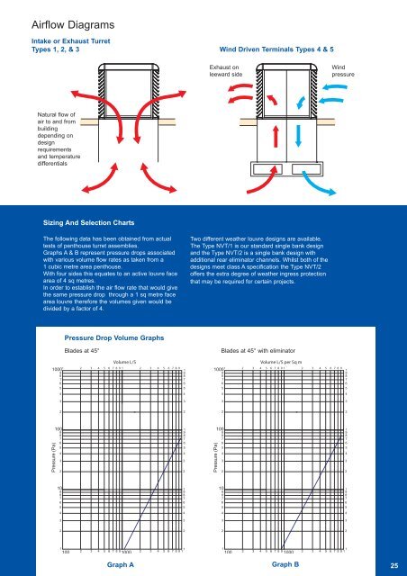
Airflow DiagramsIntake or Exhaust TurretTypes 1, 2, & 3 Wind Driven Terminals Types 4 & 5Exhaust onleeward sideWindpressureNatural flow ofair to and frombuildingdepending ondesignrequirementsand temperaturedifferentialsSizing And Selection Charts<strong>The</strong> following data has been obtained from actualtests of penthouse turret assemblies.Graphs A & B represent pressure drops associatedwith various volume flow rates as taken from a1 cubic metre area penthouse.With four sides this equates to an active louvre facearea of 4 sq metres.In order to establish the air flow rate that would givethe same pressure drop through a 1 sq metre facearea louvre therefore the volumes given would bedivided by a factor of 4.Two different weather louvre designs are available.<strong>The</strong> Type NVT/1 is our standard single bank designand the Type NVT/2 is a single bank design withadditional rear eliminator channels. Whilst both of thedesigns meet class A specification the Type NVT/2offers the extra degree of weather ingress protectionthat may be required for certain projects.Pressure Drop Volume GraphsBlades at 45°Blades at 45° with eliminator1 1000987652 3 4 5 6 7 8 9 1Volume L/S2 3 4 5 6 7 8 9 11987651 100098765Volume L/S per Sq m2 3 4 5 6 7 8 9 12 3 4 5 6 7 8 9 1198765444433332222Pressure (Pa)10098765432198765432Pressure (Pa)10098765432198765432109876519876510987651987654444333322221100 2 3 4 5 6 7 8 9 100012 3 4 5 6 7 8 9 11100 2 3 4 5 6 7 8 9 100012 3 4 5 6 7 8 9 1Graph AGraph B25