2-V 900-Mhz Quadrature Coupled LC Oscillators with ... - CiteSeerX
2-V 900-Mhz Quadrature Coupled LC Oscillators with ... - CiteSeerX
2-V 900-Mhz Quadrature Coupled LC Oscillators with ... - CiteSeerX

Create successful ePaper yourself
Turn your PDF publications into a flip-book with our unique Google optimized e-Paper software.
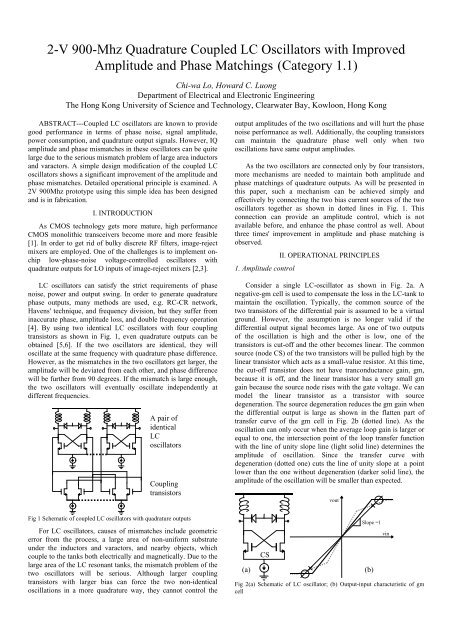
2-V <strong>900</strong>-<strong>Mhz</strong> <strong>Quadrature</strong> <strong>Coupled</strong> <strong>LC</strong> <strong>Oscillators</strong> <strong>with</strong> ImprovedAmplitude and Phase Matchings (Category 1.1)Chi-wa Lo, Howard C. LuongDepartment of Electrical and Electronic EngineeringThe Hong Kong University of Science and Technology, Clearwater Bay, Kowloon, Hong KongABSTRACT---<strong>Coupled</strong> <strong>LC</strong> oscillators are known to providegood performance in terms of phase noise, signal amplitude,power consumption, and quadrature output signals. However, IQamplitude and phase mismatches in these oscillators can be quitelarge due to the serious mismatch problem of large area inductorsand varactors. A simple design modification of the coupled <strong>LC</strong>oscillators shows a significant improvement of the amplitude andphase mismatches. Detailed operational principle is examined. A2V <strong>900</strong><strong>Mhz</strong> prototype using this simple idea has been designedand is in fabrication.I. INTRODUCTIONAs CMOS technology gets more mature, high performanceCMOS monolithic transceivers become more and more feasible[1]. In order to get rid of bulky discrete RF filters, image-rejectmixers are employed. One of the challenges is to implement onchiplow-phase-noise voltage-controlled oscillators <strong>with</strong>quadrature outputs for LO inputs of image-reject mixers [2,3].<strong>LC</strong> oscillators can satisfy the strict requirements of phasenoise, power and output swing. In order to generate quadraturephase outputs, many methods are used, e.g. RC-CR network,Havens' technique, and frequency division, but they suffer frominaccurate phase, amplitude loss, and double frequency operation[4]. By using two identical <strong>LC</strong> oscillators <strong>with</strong> four couplingtransistors as shown in Fig. 1, even quadrature outputs can beobtained [5,6]. If the two oscillators are identical, they willoscillate at the same frequency <strong>with</strong> quadrature phase difference.However, as the mismatches in the two oscillators get larger, theamplitude will be deviated from each other, and phase differencewill be further from 90 degrees. If the mismatch is large enough,the two oscillators will eventually oscillate independently atdifferent frequencies.A pair ofidentical<strong>LC</strong>oscillatorsCouplingtransistorsoutput amplitudes of the two oscillations and will hurt the phasenoise performance as well. Additionally, the coupling transistorscan maintain the quadrature phase well only when twooscillations have same output amplitudes.As the two oscillators are connected only by four transistors,more mechanisms are needed to maintain both amplitude andphase matchings of quadrature outputs. As will be presented inthis paper, such a mechanism can be achieved simply andeffectively by connecting the two bias current sources of the twooscillators together as shown in dotted lines in Fig. 1. Thisconnection can provide an amplitude control, which is notavailable before, and enhance the phase control as well. Aboutthree times' improvement in amplitude and phase matching isobserved.1. Amplitude controlII. OPERATIONAL PRINCIPLESConsider a single <strong>LC</strong>-oscillator as shown in Fig. 2a. Anegative-gm cell is used to compensate the loss in the <strong>LC</strong>-tank tomaintain the oscillation. Typically, the common source of thetwo transistors of the differential pair is assumed to be a virtualground. However, the assumption is no longer valid if thedifferential output signal becomes large. As one of two outputsof the oscillation is high and the other is low, one of thetransistors is cut-off and the other becomes linear. The commonsource (node CS) of the two transistors will be pulled high by thelinear transistor which acts as a small-value resistor. At this time,the cut-off transistor does not have tranconductance gain, gm,because it is off, and the linear transistor has a very small gmgain because the source node rises <strong>with</strong> the gate voltage. We canmodel the linear transistor as a transistor <strong>with</strong> sourcedegeneration. The source degeneration reduces the gm gain whenthe differential output is large as shown in the flatten part oftransfer curve of the gm cell in Fig. 2b (dotted line). As theoscillation can only occur when the average loop gain is larger orequal to one, the intersection point of the loop transfer function<strong>with</strong> the line of unity slope line (light solid line) determines theamplitude of oscillation. Since the transfer curve <strong>with</strong>degeneration (dotted one) cuts the line of unity slope at a pointlower than the one <strong>with</strong>out degeneration (darker solid line), theamplitude of the oscillation will be smaller than expected.voutFig 1 Schematic of coupled <strong>LC</strong> oscillators <strong>with</strong> quadrature outputsFor <strong>LC</strong> oscillators, causes of mismatches include geometricerror from the process, a large area of non-uniform substrateunder the inductors and varactors, and nearby objects, whichcouple to the tanks both electrically and magnetically. Due to thelarge area of the <strong>LC</strong> resonant tanks, the mismatch problem of thetwo oscillators will be serious. Although larger couplingtransistors <strong>with</strong> larger bias can force the two non-identicaloscillations in a more quadrature way, they cannot control the(a)CSSlope =1Fig 2(a) Schematic of <strong>LC</strong> oscillator; (b) Output-input characteristic of gmcell(b)vin
Ideally, the differential amplitude can be as large as theproduct of the bias current and the equivalent parallel resistanceof one <strong>LC</strong> tank.If a large capacitor is connected from the common sourcenode to ground as shown in Fig. 3, the ac ground at the nodewould be maintained (curve 2 in Fig. 4b) and the gm gain wouldnot be degraded. When the differential output of the oscillator issmall, the gm cell does not require so much current from thecurrent source and the extra current is stored in the capacitor.When the differential output of the oscillator is larger, the gmcell requires more current and draws current from the capacitoras shown in Fig. 3 and curve 2 in Fig. 4c. The transfer curvewould be similar to the ideal one <strong>with</strong>out source degeneration(solid line in Fig. 2b). According to the simulation, larger andcloser-to-theoretical amplitude is obtained (curve 2 in Fig. 4a)<strong>with</strong> a large capacitor (e.g. 100pF). Better phase noise is alsoexpected due to the absence of the noisy degeneration resistance.As a comparison, the corresponding waveforms for the originaloscillator <strong>with</strong>out a capacitor are shown as curves 1 in Fig. 4.(a)(b)Mid. Mid. Hi.Lo.(Lo.)(Hi.)Fig 3(a) Less current flow in gm cell when small differential output; (b) Morecurrent flow in gm cell when large differential output(1) (2)(1)(2)(1)(2)Fig 4(a) Single-ended output voltage of <strong>LC</strong> oscillator; (b) Common sourcevoltage; (c) Current flow into gm cell. (1) <strong>with</strong>out capacitor (2) <strong>with</strong>capacitorIn practice, it is not desirable to use such a huge capacitor inthe circuit. In coupled <strong>LC</strong> oscillators, the similar effect and resultcan be achieved if their bias current sources are connectedtogether (Fig. 5). For example, <strong>with</strong>out loss of generality, let usassume that the differential output of oscillator A is small andthe differential output of oscillator B is large. Oscillator A doesnot need much current while oscillator B wants more. OscillatorA can supply its extra current to oscillator B. One-fourth periodlater, oscillator B output becomes small, and oscillator A outputbecomes large. Oscillator B has extra current to return tooscillator A. For both oscillators, the other oscillator functionsjust like a capacitor connected to its common source node.Compared to circuit in Fig. 3, the circuit works the same way. Asshown in Fig. 6 and similar to the case <strong>with</strong> a capacitor shown inFig. 4, a larger and closer-to-theoretical output amplitude, aflatten common source voltage, and a gm cell current <strong>with</strong> extracurrent pulses can be observed.(a)(b)(c)Mid. Mid. Hi.Lo.(Lo.)(Hi.)Fig 5 Current flows in two oscillators <strong>with</strong> 90-degree phase difference(2)(1)(1)(2)(1)(2)Fig 6(a) Output voltage of <strong>LC</strong> oscillator; (b) Common source voltage; (c)Current flow into gm cell. (1) <strong>with</strong>out common source node connection (2)<strong>with</strong> connectionIn addition to providing larger amplitude and better phasenoise, connecting the two current sources can also maintain thematching of the amplitudes of the two coupled oscillators. Forexample, oscillator A has larger output amplitude and oscillatorB has smaller output amplitude due to the unmatched <strong>LC</strong> tanks.Since oscillator B has smaller amplitude, it cannot store andrelease too much current for oscillator A. Oscillator A will seeoscillator B as a small-value capacitor. On the contrary, oscillatorB will see oscillator A as a large value capacitor. As shown inFigs. 7a and 7b, when the differential output is large, smallervoltage ripples at the common source node and larger peakcurrent pulse are observed for oscillator B (T2) as compared tothose for oscillator A (T1). The amplitudes of both oscillatorswill be increased due to the parallel capacitors but the amplitudeof oscillator B will be increased more due to a larger capacitorconnected. This mechanism can reduce the amplitude mismatchof the oscillator due to the mismatch between the two <strong>LC</strong> tanks.Both increase in amplitude and decrease in amplitude mismatchcan be observed in simulation (Fig. 8). This amplitude control isa result of the parallel capacitor effect only because the averagebias currents in two unmatched oscillators are the same, just likethe case <strong>with</strong> a capacitor in parallel.T1 T2 T1 T2 T1(1)Osc A Osc B(2).Fig 7(a) Common source voltage of mismatch coupled <strong>LC</strong> oscillators; (b) (1)Current in smaller-amplitude oscillator A (2) Current in larger-amplitudeoscillator B. T1: period when differential output is large in oscillator A; T2:period when differential output is large in oscillator B(a)(b)(c)(a)(b)
(b) I+ output (b) Q+ output(a) I+ output (a) Q+ output(2)(1)Fig 8 IQ outputs of coupled <strong>LC</strong> oscillators (a) <strong>with</strong>out common sourceconnection and (b) <strong>with</strong> connection2. <strong>Quadrature</strong> Phase ControlA better phase matching can be obtained for the quadratureoutputs of the proposed <strong>LC</strong> oscillator due to the better-matchedoutput amplitudes and the current interaction between the twooscillators.a) Matched output amplitudesThe four coupling transistors force the two oscillators tooscillate at the same frequency and 90-degree out-of-phase.However, the quadrature phase can be maintained only if theamplitudes of the two oscillators are the same. A simplesimulation using the circuit shown in Fig. 9 can show this. Sincethe output amplitudes of the two oscillators, which share thesame current source, are more matched, the four couplingtransistors can maintain the quadrature phase better.To the outputs of the two identical <strong>LC</strong> oscillators1 1 A AFig 9 Circuit to verify imperfect control of the phase for different IQamplitudesb) Current interactionThe two oscillators can supply extra current for each otherwhen more current is needed to enhance both oscillations if theyoscillate at the same frequency <strong>with</strong> quadrature phase difference.This effect favors them to oscillate at the same frequency and<strong>with</strong> a 90-degree phase difference than any other condition. Thismechanism can be proved by two identical oscillators <strong>with</strong> onlythe current sources being connected together but <strong>with</strong>out fourcoupling transistors. After startup, they can automaticallyoscillate <strong>with</strong> 90-degree out-of-phase (Fig. 10). Another evidenceis that a pair of coupled oscillators <strong>with</strong> shared current sourcecan always form the quadrature relationship between the outputsmuch faster as shown in Fig. 11.Fig 11 Phase error <strong>with</strong> time of coupled <strong>LC</strong> oscillators (1) <strong>with</strong>out commonsource connection and (2) <strong>with</strong> connectionIII. DESIGN CONSIDERATIONSIn addition to the <strong>LC</strong> oscillator, the size of the four couplingtransistors and their bias need to be designed. The fourtransistors form a 4-stage-ring-oscillator-like frame for the two<strong>LC</strong> oscillators to be put inside. The frame tries to maintain thequadrature-phase relationship between the two <strong>LC</strong> oscillators,while the two imperfectly-matched <strong>LC</strong> oscillators try to oscillateat different frequencies and break the quadrature-phaserelationship. At the same time, the <strong>LC</strong> oscillators maintain thepurity of the frequency while the ring oscillator gives a poorphase noise. Thus, it is a tradeoff between the quadrature-phasemaintenance and the phase-noise performance. The ratio oftransistor sizes and biases of the coupling transistors (the ringoscillator) to the negative feedback transistors in <strong>LC</strong> oscillatordetermines whether the whole oscillator is closer to being eithera ring oscillator <strong>with</strong> poor phase noise but good phase matchingor a <strong>LC</strong> oscillator <strong>with</strong> poor phase matching but good phasenoise. The tradeoff should be made based on the mismatches ofthe <strong>LC</strong> tanks, the quadrature phase and phase noise requirements.Fortunately, by connecting the two bias current sources together,the quadrature-phase relationship becomes stronger and thecoupling transistors can be smaller to reduce the noise andincrease the tuning range of the oscillator. Similar to the twonegative gm cells, the common source nodes of couplingtransistors are also connected together to increase the gain andimprove the matchings. However, less significant effect isobserved due to the smaller size and bias.IV. LAYOUT CONSIDERATIONSGood matching of the transistors is important to maintain agood quadrature outputs <strong>with</strong> amplitude and phase matchings.Instead of putting two identical oscillators together, they have tobe considered and laid out as a whole. Instead of pairs oftransistors, groups of four transistors have to be matched bylayout techniques, such as interleaving, common centroid androtational symmetry. A special floorplan technique is used tomatch two oscillators. For good IQ matching, every transistor issplitted into two to match <strong>with</strong> the transistors of 90-degree phaselag and 90-degree phase lead (Fig. 12a).I- Q+IQIQQIQIFig 10 Output voltage waveform of two <strong>LC</strong> oscillators <strong>with</strong> common sourcenode connection onlyQ-I+(a) (b) (c)Fig 12(a) Floorplan of gm cell transistors (matched pairs in dottedrectangles); (b) Floorplan of inductors <strong>with</strong> rotational symmetry; (c)Floorplan of inductors <strong>with</strong> x-y symmetry and common centroidNot only the positions but also the orientations of theinductors are important because of the mutual effects of themagnetic flux of the inductors. Different positions and
orientations have been considered. The best one <strong>with</strong> rotationalsymmetry and common centroid cannot be used because it wouldbe impossible to connect the outputs to outside <strong>with</strong>out affectingthe symmetry. The output wiring would affect and be affected bythe left and right inductors (Fig. 12b). As a compromise, afloorplan <strong>with</strong> x- and y- mirror symmetries and common centroid(Fig. 12c) is used in the prototype. The whole layout is shown inFig. 13. The dimension of the design is 950 µm X 950 µm.Since the DC voltage drop across the negative gm cell in thedesign is approximately 1V, it is possible to implement theoscillator at 1V supply <strong>with</strong> the same performance whileconsuming half power by increasing the size of the bias transistorto minimize its drain-to-source voltage drop. However, theprototype has been designed at 2V due to the voltagespecification of the frequency synthesizer in which the oscillatoris used. Performances of the prototype oscillator are summarizedin Table 1, and the fabrication is underway.Table 1. Summary of performancesFig 13 Layout of whole <strong>LC</strong> oscillatorV. SIMULATION RESULTSA pair of 2V <strong>900</strong>-<strong>Mhz</strong> quadrature coupled <strong>LC</strong> oscillators<strong>with</strong> the additional connection at the current sources has beendesigned using a MOSIS 0.8um process. Simulating <strong>with</strong> BSIM3models, different degrees of mismatches of the resonant tanksare tested. For simplicity, cases <strong>with</strong> different values ofmismatches of varactors in <strong>LC</strong> tanks are simulated. Simulationresults show that there are about 3 times' improvement in bothamplitude and phase matching (Fig. 14a). In both original andour proposed design, the oscillators will malfunction when thephase and gain mismatches are larger than 15% and 5 degrees,respectively. However, for our proposal, the tolerance to degreeof mismatch of the <strong>LC</strong> tank for stable single frequencyoscillation and constant phase difference is improved by about 3times (Fig. 14b) because the phase and amplitude mismatches areless for same <strong>LC</strong> tank mismatch. Similar improvements inamplitude and phase matchings are observed for mismatchesfrom other sources, e.g. inductor values, quality factors,transistors' parameters.Typical designTypical designOur proposed design(a)Our proposed designFig 14a Amplitude mismatch <strong>with</strong> mismatch error in varactors; Fig 14bphase mismatch <strong>with</strong> mismatch error in varactors(b)Supply VoltagePower consumptionSingle-end amplitudeCenter frequencyTuning rangephase noise2 V22 mW1.6 Vpp<strong>900</strong> MHz~100 MHz-105 dBc/Hz @100kHz offsetVI. LIMITATIONSThe proposed feedback mechanism to control the amplitudeis achieved by changing the effective capacitance in parallel tothe source node. However, the capacitance in parallel can onlylead the amplitude of oscillation to a closer-to-theoretical one.The feedback gain is finite and decreases as the amplitudeincreases, thus the amplitude control is not perfect and there willexist a non-zero steady-state error in the amplitude. We can onlyreduce the amplitude error but cannot eliminate it. Similarly, wecan only enhance the phase control mechanism to reduce thephase error due to the circuit mismatches but cannot completelycancel it.VII. CONCLUSIONA simple design modification, virtually at no cost, to thequadrature coupled <strong>LC</strong> oscillators has been described andexplained in details. This modification provides an automaticamplitude-matching control which is not available in the originaldesign and enhances significantly the quadrature-phase control.With such a control, better amplitude and phase matchings canbe obtained even in the presence of large mismatch of the <strong>LC</strong>tanks. The tolerance of the <strong>LC</strong> tanks mismatches for a stablesingle frequency oscillation is much increased. Better phasenoise is expected as well due to the increase in amplitude and amore solid ac ground for the common source. The improvementhas been verified by simulation, and a prototype has beendesigned and is fabricated. Some design and layout issues uniquein coupled <strong>LC</strong> oscillators are also discussed.REFERENCES[1] P. Gray, R. Meyer, "Future Directions in Silicon ICs for RFPersonal Communications," Proceedings of the IEEE 1995Custom integrated Circuits Conference, pp 83-90, May 1995[2] H. Takahashi, et al, "A Direct Conversion Receiver Utilizinga Novel FSK Demodulator and a Low-Power Consumption<strong>Quadrature</strong> <strong>Quadrature</strong> Mixer," 42 nd IEE VehicularTechnology Conference, pp.910-915, May 1992[3] T. Lee, The Design of CMOS Radio-Frequency IntegratedCircuits, Cambridge University Press, 1998.[4] B. Razavi, RF Microelectronics, Prentice Hall PTR, 1998.[5] A. Rofougaran, et al, "A <strong>900</strong><strong>Mhz</strong> CMOS <strong>LC</strong>-oscillator <strong>with</strong>quadrate outputs," ISSCC Digest of technical papers,pp.392-393, Feb. 1996.[6] B. Razavi, et al,"A 1.8Ghz CMOS voltage-controlledoscillator," ISSCC Digest of technical papers, pp. 388-399,Feb. 1997.