Microring and microdisk resonator integrated circuits on a silicon chip
Microring and microdisk resonator integrated circuits on a silicon chip
Microring and microdisk resonator integrated circuits on a silicon chip

You also want an ePaper? Increase the reach of your titles
YUMPU automatically turns print PDFs into web optimized ePapers that Google loves.
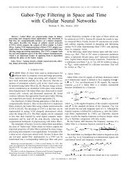
<str<strong>on</strong>g>Microring</str<strong>on</strong>g> <str<strong>on</strong>g>and</str<strong>on</strong>g> <str<strong>on</strong>g>microdisk</str<strong>on</strong>g> <str<strong>on</strong>g>res<strong>on</strong>ator</str<strong>on</strong>g> <str<strong>on</strong>g>integrated</str<strong>on</strong>g> <str<strong>on</strong>g>circuits</str<strong>on</strong>g> <strong>on</strong> a silic<strong>on</strong> <strong>chip</strong>Andrew W. Po<strong>on</strong>, Linjie Zhou, Chao Li, Nick K. H<strong>on</strong>, <str<strong>on</strong>g>and</str<strong>on</strong>g> Hui ChenPhot<strong>on</strong>ic Device Laboratory, Department of Electr<strong>on</strong>ic <str<strong>on</strong>g>and</str<strong>on</strong>g> Computer Engineering, The H<strong>on</strong>g K<strong>on</strong>gUniversity of Science <str<strong>on</strong>g>and</str<strong>on</strong>g> Technology, Clear Water Bay, The H<strong>on</strong>g K<strong>on</strong>g Special AdministrativeRegi<strong>on</strong>, ChinaPh<strong>on</strong>e: 852-2358-7905; fax: 852-2358-1485; email: eeawpo<strong>on</strong>@ust.hkABSTRACTWe report our latest experimental <str<strong>on</strong>g>and</str<strong>on</strong>g> numerical work <strong>on</strong> silic<strong>on</strong> micro<str<strong>on</strong>g>res<strong>on</strong>ator</str<strong>on</strong>g> passive <str<strong>on</strong>g>and</str<strong>on</strong>g> electro-optic active devices.On the passive device fr<strong>on</strong>t, we dem<strong>on</strong>strate an electrically tunable silic<strong>on</strong> microring notch filter for c<strong>on</strong>verting 3.6-Gbpsn<strong>on</strong>-return-to-zero (NRZ) data format to return-to-zero (RZ)-like data format. We show that the c<strong>on</strong>verted RZ-like dataquality highly depends <strong>on</strong> the notch filter extincti<strong>on</strong> ratios. On the active device fr<strong>on</strong>t, we dem<strong>on</strong>strate a silic<strong>on</strong>microring modulator using a double-coupled U-bend waveguide as a feedback <str<strong>on</strong>g>and</str<strong>on</strong>g> a pair of laterally <str<strong>on</strong>g>integrated</str<strong>on</strong>g> injecti<strong>on</strong>typep-i-n diodes for bias/signal modulati<strong>on</strong>. We show that the microring modulator extincti<strong>on</strong> ratios are electricallyc<strong>on</strong>trolled by applying a DC-bias across either the feedback-waveguide or the microring while applying a modulati<strong>on</strong>signal across the other p-i-n diode. We also propose silic<strong>on</strong> <str<strong>on</strong>g>microdisk</str<strong>on</strong>g> modulators with selectively <str<strong>on</strong>g>integrated</str<strong>on</strong>g> depleti<strong>on</strong>typeSchottky diodes. Our numerical simulati<strong>on</strong>s suggest that the <str<strong>on</strong>g>microdisk</str<strong>on</strong>g> structures can be advantageous comparedwith microring structures. We show that electrical rise time <strong>on</strong> the order of a few ps is feasible using <str<strong>on</strong>g>microdisk</str<strong>on</strong>g>s. Wealso allude to <strong>on</strong>-going work <strong>on</strong> extending the micro<str<strong>on</strong>g>res<strong>on</strong>ator</str<strong>on</strong>g> devices discussed here to building functi<strong>on</strong>al silic<strong>on</strong>optoelectr<strong>on</strong>ics <str<strong>on</strong>g>integrated</str<strong>on</strong>g> <str<strong>on</strong>g>circuits</str<strong>on</strong>g>.Keywords: silic<strong>on</strong> microring, silic<strong>on</strong> <str<strong>on</strong>g>microdisk</str<strong>on</strong>g>, silic<strong>on</strong> micro<str<strong>on</strong>g>res<strong>on</strong>ator</str<strong>on</strong>g>s, free-carrier plasma dispersi<strong>on</strong>, silic<strong>on</strong>phot<strong>on</strong>ics, silic<strong>on</strong> optoelectr<strong>on</strong>ics <str<strong>on</strong>g>integrated</str<strong>on</strong>g> <str<strong>on</strong>g>circuits</str<strong>on</strong>g>1. INTRODUCTIONSilic<strong>on</strong> micrometer-scale ring/disk <str<strong>on</strong>g>res<strong>on</strong>ator</str<strong>on</strong>g> devices that are fabricated by the mature CMOS-compatible processes haverecently attracted c<strong>on</strong>siderable interests for optical signal processing applicati<strong>on</strong>s <strong>on</strong> phot<strong>on</strong>ics <strong>chip</strong>s including in nextgenerati<strong>on</strong>wavelength-agile optical networks [1], as comp<strong>on</strong>ents for optical interc<strong>on</strong>nects <strong>on</strong> computer <strong>chip</strong>s [2-4], <str<strong>on</strong>g>and</str<strong>on</strong>g>as <strong>on</strong>-<strong>chip</strong> refractive-index-based label-free biosensors [5, 6]. As an <str<strong>on</strong>g>integrated</str<strong>on</strong>g> narrowb<str<strong>on</strong>g>and</str<strong>on</strong>g> optical filter, silic<strong>on</strong>microring <str<strong>on</strong>g>res<strong>on</strong>ator</str<strong>on</strong>g>-based channel add-drop <str<strong>on</strong>g>and</str<strong>on</strong>g> notch filters have attained high quality factors Q ~ 10 5 [7, 8]. Majorityof the dem<strong>on</strong>strated silic<strong>on</strong> micro<str<strong>on</strong>g>res<strong>on</strong>ator</str<strong>on</strong>g>s are based <strong>on</strong> c<strong>on</strong>venti<strong>on</strong>al circular/racetrack microring [7-11] <str<strong>on</strong>g>and</str<strong>on</strong>g> <str<strong>on</strong>g>microdisk</str<strong>on</strong>g>[12, 13] <str<strong>on</strong>g>res<strong>on</strong>ator</str<strong>on</strong>g>s, with alternative devices from our research group using polyg<strong>on</strong>al-shaped [14-17] <str<strong>on</strong>g>and</str<strong>on</strong>g> spiral-shaped[18, 19] <str<strong>on</strong>g>microdisk</str<strong>on</strong>g> <str<strong>on</strong>g>res<strong>on</strong>ator</str<strong>on</strong>g>s.Various silic<strong>on</strong> micro<str<strong>on</strong>g>res<strong>on</strong>ator</str<strong>on</strong>g>-based switches <str<strong>on</strong>g>and</str<strong>on</strong>g> modulators using thermooptical [20], mechanical [21], optical [22],<str<strong>on</strong>g>and</str<strong>on</strong>g> electrooptical (EO) [23-25] mechanisms have been dem<strong>on</strong>strated. Am<strong>on</strong>g these micro<str<strong>on</strong>g>res<strong>on</strong>ator</str<strong>on</strong>g> tuning methods, EOtuning by means of the well-understood free-carrier plasma dispersi<strong>on</strong> effect in silic<strong>on</strong> [26] offers an appealingcombinati<strong>on</strong> of bey<strong>on</strong>d-GHz-speed switching, as well as the possibility of electr<strong>on</strong>ic c<strong>on</strong>trol using CMOS <str<strong>on</strong>g>circuits</str<strong>on</strong>g> <strong>on</strong> thesilic<strong>on</strong> substrate. Specifically, Xu et al. in their pi<strong>on</strong>eering work [23] dem<strong>on</strong>strated GHz-speed silic<strong>on</strong> microringmodulators with laterally <str<strong>on</strong>g>integrated</str<strong>on</strong>g> injecti<strong>on</strong>-type p-i-n diodes. Owing to the high-Q res<strong>on</strong>ance sensitivity to minuterefractive index changes, the optical rise time at a probe wavelength near res<strong>on</strong>ance can be of order of magnitude shorterthan the electrical rise time (carrier transit time), <str<strong>on</strong>g>and</str<strong>on</strong>g> is not limited by the slow carrier recombinati<strong>on</strong> time. Mostrecently, Xu et al. [24] has further dem<strong>on</strong>strated their silic<strong>on</strong> EO microring modulators up to 4-GHz modulati<strong>on</strong>b<str<strong>on</strong>g>and</str<strong>on</strong>g>width. On the industry end, Luxtera Inc. [25] has reported 10-Gbps microring EO modulators using laterally
<str<strong>on</strong>g>integrated</str<strong>on</strong>g> depleti<strong>on</strong>-type p-n diode. Previously, our research group also dem<strong>on</strong>strated a silic<strong>on</strong> <str<strong>on</strong>g>microdisk</str<strong>on</strong>g> EO modulatorusing laterally <str<strong>on</strong>g>integrated</str<strong>on</strong>g> injecti<strong>on</strong>-type p-i-n diode with modulati<strong>on</strong> 3-dB b<str<strong>on</strong>g>and</str<strong>on</strong>g>width up to ~500 MHz [27].Given the impressive track record of silic<strong>on</strong> micro<str<strong>on</strong>g>res<strong>on</strong>ator</str<strong>on</strong>g> devices, it is thus c<strong>on</strong>ceivable that silic<strong>on</strong> micro<str<strong>on</strong>g>res<strong>on</strong>ator</str<strong>on</strong>g>optoelectr<strong>on</strong>ics <str<strong>on</strong>g>integrated</str<strong>on</strong>g> <str<strong>on</strong>g>circuits</str<strong>on</strong>g> (OEICs) will be the next major step forward in order to provide optical signalprocessing functi<strong>on</strong>ality bey<strong>on</strong>d any single devices can offer. Indeed, the year 2006 has seen several silic<strong>on</strong>micro<str<strong>on</strong>g>res<strong>on</strong>ator</str<strong>on</strong>g> OEIC work including modulati<strong>on</strong> of four different WDM channels using cascaded microring modulators[24], <str<strong>on</strong>g>and</str<strong>on</strong>g> vertical integrati<strong>on</strong> of a <str<strong>on</strong>g>microdisk</str<strong>on</strong>g> add-drop filter with a CMOS transistor in a three-dimensi<strong>on</strong>al structure [13].Here we report our latest experimental <str<strong>on</strong>g>and</str<strong>on</strong>g> numerical work <strong>on</strong> three microring <str<strong>on</strong>g>and</str<strong>on</strong>g> <str<strong>on</strong>g>microdisk</str<strong>on</strong>g> <str<strong>on</strong>g>res<strong>on</strong>ator</str<strong>on</strong>g>-based passive<str<strong>on</strong>g>and</str<strong>on</strong>g> EO active devices recently proposed by our research group. For passive device applicati<strong>on</strong>s, we exploit ourmicroring <str<strong>on</strong>g>res<strong>on</strong>ator</str<strong>on</strong>g>s for data format c<strong>on</strong>versi<strong>on</strong>. For active device applicati<strong>on</strong>s, we dem<strong>on</strong>strate microring carrierinjecti<strong>on</strong>-type EO modulators with external-feedback c<strong>on</strong>trol. We also numerically study the use of carrier depleti<strong>on</strong>typeSchottky diodes in <str<strong>on</strong>g>microdisk</str<strong>on</strong>g> modulators. This paper is divided into the following secti<strong>on</strong>s: secti<strong>on</strong> 2 <strong>on</strong> silic<strong>on</strong>microring filters for data format c<strong>on</strong>versi<strong>on</strong>, secti<strong>on</strong> 3 <strong>on</strong> silic<strong>on</strong> microring EO modulators with external feedback,secti<strong>on</strong> 4 <strong>on</strong> silic<strong>on</strong> <str<strong>on</strong>g>microdisk</str<strong>on</strong>g> EO modulators using selectively <str<strong>on</strong>g>integrated</str<strong>on</strong>g> depleti<strong>on</strong>-type Schottky diodes, <str<strong>on</strong>g>and</str<strong>on</strong>g> secti<strong>on</strong> 5c<strong>on</strong>cludes the paper with discussi<strong>on</strong> <strong>on</strong> future work.2. SILICON MICRORING FILTERS FOR NRZ-TO-PRZ FORMAT CONVERSIONOptical clock recovery is an essential signal processing in optical communicati<strong>on</strong>s. Current optical networks mostlyemploy n<strong>on</strong>-return-to-zero (NRZ) data format [28], which does not carry a str<strong>on</strong>g clock comp<strong>on</strong>ent. Thus, clockrecovery relies <strong>on</strong> first c<strong>on</strong>verting the NRZ format into return-to-zero (RZ)-like data format, which carries a str<strong>on</strong>g clockcomp<strong>on</strong>ent. The RZ-like format is comm<strong>on</strong>ly referred to as pseudo-RZ (PRZ) format. C<strong>on</strong>venti<strong>on</strong>al approaches forNRZ-to-PRZ format c<strong>on</strong>versi<strong>on</strong> use linear [29, 30] <str<strong>on</strong>g>and</str<strong>on</strong>g> n<strong>on</strong>linear [31, 32] approaches, as well as <str<strong>on</strong>g>integrated</str<strong>on</strong>g> optics in theform of asymmetric Mach-Zehnder interferometers (AMZIs) [33]. Most recently [34], we proposed <str<strong>on</strong>g>and</str<strong>on</strong>g> reported initialdem<strong>on</strong>strati<strong>on</strong> of using silic<strong>on</strong> microring notch filters for NRZ-to-PRZ format c<strong>on</strong>versi<strong>on</strong>. The method is a linearlyoptics approach <str<strong>on</strong>g>and</str<strong>on</strong>g> highly <str<strong>on</strong>g>integrated</str<strong>on</strong>g>. Here we report further experimental dem<strong>on</strong>strati<strong>on</strong> using electrically tunablemicroring <str<strong>on</strong>g>res<strong>on</strong>ator</str<strong>on</strong>g>s with laterally <str<strong>on</strong>g>integrated</str<strong>on</strong>g> p-i-n diodes under various forward biases.Fig.1. Schematics of the working principle of the microring <str<strong>on</strong>g>res<strong>on</strong>ator</str<strong>on</strong>g> notch filter-based NRZ-to-PRZ format c<strong>on</strong>verter. (a) An inputNRZ signal, a notch filter transmissi<strong>on</strong>, <str<strong>on</strong>g>and</str<strong>on</strong>g> the c<strong>on</strong>verted PRZ signal in frequency domain. The carrier wavelength of the input NRZsignal is at the microring notch filter wavelength λ 0 . Inset: schematic of the waveguide-coupled microring <str<strong>on</strong>g>res<strong>on</strong>ator</str<strong>on</strong>g>-based notch filter.(b) Schematic waveforms of the input NRZ signal <str<strong>on</strong>g>and</str<strong>on</strong>g> the c<strong>on</strong>verted PRZ signal. The c<strong>on</strong>verted PRZ signal pulses follow thetransiti<strong>on</strong> edges of the input NRZ signal.Figure 1 illustrates the working principle of the microring <str<strong>on</strong>g>res<strong>on</strong>ator</str<strong>on</strong>g> notch filter-based NRZ-to-PRZ format c<strong>on</strong>verter[34]. Fig. 1(a) shows the schematics of an input NRZ signal, a notch filter transmissi<strong>on</strong>, <str<strong>on</strong>g>and</str<strong>on</strong>g> the c<strong>on</strong>verted PRZ signal,all in frequency domain. The inset depicts the schematic of the microring notch filter comprising a single-modesubmicrometer waveguide laterally coupled to a racetrack microring <str<strong>on</strong>g>res<strong>on</strong>ator</str<strong>on</strong>g>. Optical NRZ signal is launched into the
us waveguide with the carrier wavelength at the microring notch filter wavelength λ 0 . After passing through the notchfilter, the NRZ signal is c<strong>on</strong>verted to a PRZ signal by suppressing the optical carrier frequency comp<strong>on</strong>ents <str<strong>on</strong>g>and</str<strong>on</strong>g>effectively enhancing the optical clock comp<strong>on</strong>ents in the notch filter transmissi<strong>on</strong>. In time domain, the transmissi<strong>on</strong>signal appears as discrete PRZ pulses corresp<strong>on</strong>ding to the transiti<strong>on</strong> edges of the NRZ signal, as shown in Fig. 1(b).Fig. 2. (a) Optical micrograph of an actively tunable racetrack microring <str<strong>on</strong>g>res<strong>on</strong>ator</str<strong>on</strong>g> notch filter with laterally <str<strong>on</strong>g>integrated</str<strong>on</strong>g> p-i-n diode <strong>on</strong>an SOI substrate. Inset: cross-secti<strong>on</strong>al schematic of the p-i-n diode. (b) Measured TE-polarized throughput-port spectrum up<strong>on</strong>various forward biases. (c) – (f) Measured transmissi<strong>on</strong> of a 3.6-Gbps NRZ signal at (c) an off-res<strong>on</strong>ance carrier wavelength (1546nm, cyan line), (d) an <strong>on</strong>-res<strong>on</strong>ance carrier wavelength under 0-V forward bias (1546.9 nm, blue line), (e) an <strong>on</strong>-res<strong>on</strong>ance carrierwavelength under 1.2-V forward bias (1546.15 nm, red line), <str<strong>on</strong>g>and</str<strong>on</strong>g> (f) an <strong>on</strong>-res<strong>on</strong>ance carrier wavelength under 1.4-V forward bias(1545.68 nm, yellow line).Figure 2(a) shows an optical micrograph of our fabricated racetrack microring <str<strong>on</strong>g>res<strong>on</strong>ator</str<strong>on</strong>g>-based notch filter with laterally<str<strong>on</strong>g>integrated</str<strong>on</strong>g> p-i-n diode surrounding most of the microring <strong>on</strong> a silic<strong>on</strong>-<strong>on</strong>-insulator (SOI) substrate. The fabricati<strong>on</strong>employs i-line optical lithography <str<strong>on</strong>g>and</str<strong>on</strong>g> dry etching as in our previous work [27]. The <str<strong>on</strong>g>integrated</str<strong>on</strong>g> diode enables active EOtuning in order to match the notch filter wavelength with the signal carrier wavelength. The racetrack arc radius is 25µm <str<strong>on</strong>g>and</str<strong>on</strong>g> the straight interacti<strong>on</strong> length is 10 µm. Inset shows the cross-secti<strong>on</strong>al schematic of the laterally <str<strong>on</strong>g>integrated</str<strong>on</strong>g> p-indiode. The rib waveguide in the intrinsic regi<strong>on</strong> has a width of 0.4 µm, a height of 0.21 µm, <str<strong>on</strong>g>and</str<strong>on</strong>g> an etched depth of0.18 µm. The p + -doped (2x10 19 cm -3 ) <str<strong>on</strong>g>and</str<strong>on</strong>g> n + -doped (1x10 20 cm -3 ) regi<strong>on</strong>s are positi<strong>on</strong>ed in the slab layer, with ~0.5-µmseparati<strong>on</strong>s from the waveguide sidewalls.Figure 2(b) shows the measured TE-polarized (electric field in the device plane) transmissi<strong>on</strong> spectra with the p-i-ndiode forward biased at 0 V, 1.0 V, 1.2 V, <str<strong>on</strong>g>and</str<strong>on</strong>g> 1.4 V. Under 0-V bias, the transmissi<strong>on</strong> dip (Q ~ 5,000) <strong>on</strong>ly exhibits anextincti<strong>on</strong> ratio (ER) of ~6 dB. As the diode is gradually forward biased (bey<strong>on</strong>d the threshold voltage of ~0.75 V), thecarrier-induced res<strong>on</strong>ance wavelength blueshift <str<strong>on</strong>g>and</str<strong>on</strong>g> the ER increases with forward biases until reaching an optimum at~18 dB up<strong>on</strong> a 1.2-V bias, suggesting a transiti<strong>on</strong> from over-coupling to critical coupling regimes.Figures 2(c) – 2(f) show the measured 3.6-Gbps NRZ signal transmissi<strong>on</strong> waveforms at an off-res<strong>on</strong>ance wavelength (0-V bias) <str<strong>on</strong>g>and</str<strong>on</strong>g> at <strong>on</strong>-res<strong>on</strong>ance wavelengths up<strong>on</strong> forward biases at 0 V, 1.2 V, <str<strong>on</strong>g>and</str<strong>on</strong>g> 1.4 V. The off-res<strong>on</strong>ance waveformlargely follows the input NRZ signal (except for the ripples observed in the optical waveform). The optical signaldisplays a rise time of ~30 ps <str<strong>on</strong>g>and</str<strong>on</strong>g> a fall time of ~35 ps. The <strong>on</strong>-res<strong>on</strong>ance waveform up<strong>on</strong> 1.2-V bias displays PRZpulses following the transiti<strong>on</strong> edges with pulse widths of ~36 ps <str<strong>on</strong>g>and</str<strong>on</strong>g> a peak extincti<strong>on</strong> ratio of ~6 dB for the rising edgepulses. The shorter NRZ signal rise time gives rise to higher PRZ pulse amplitudes. Whereas, the <strong>on</strong>-res<strong>on</strong>ancewaveform up<strong>on</strong> 0-V (1.4-V) bias displays a distorted NRZ signal, with an overshoot at the signal falling (rising) edge<str<strong>on</strong>g>and</str<strong>on</strong>g> a dip followed with a slight peak at the signal rising (falling) edge. We note that the relatively low ERs (< 10 dB)up<strong>on</strong> 0-V <str<strong>on</strong>g>and</str<strong>on</strong>g> 1.4-V biases render less optical carrier suppressi<strong>on</strong> <str<strong>on</strong>g>and</str<strong>on</strong>g> thereby less pr<strong>on</strong>ounced clock comp<strong>on</strong>ents.3. SILICON MICRORING ELECTRO-OPTIC MODULATORS WITH EXTERNAL FEEDBACKIn this secti<strong>on</strong>, we extend our actively tunable silic<strong>on</strong> microring notch filter work to an actively rec<strong>on</strong>figurable EOmodulator. We propose <str<strong>on</strong>g>and</str<strong>on</strong>g> initially dem<strong>on</strong>strate a silic<strong>on</strong> microring EO modulator that can be actively tuned by meansof an external feedback. The c<strong>on</strong>cept is based <strong>on</strong> our previous work <strong>on</strong> silic<strong>on</strong> microring notch filter comprising amicroring that is double-coupled to a U-bend waveguide [35]. Here as a modulator, both the microring <str<strong>on</strong>g>and</str<strong>on</strong>g> the feedback
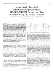
waveguide are laterally <str<strong>on</strong>g>integrated</str<strong>on</strong>g> with p-i-n diodes, allowing biasing <str<strong>on</strong>g>and</str<strong>on</strong>g> signal modulati<strong>on</strong> to be separately appliedacross the two sets of p-i-n diodes. The biasing electrically tunes the res<strong>on</strong>ance wavelength <str<strong>on</strong>g>and</str<strong>on</strong>g> ER.Fig. 3. (a) Schematic of the proposed silic<strong>on</strong> microring EO modulator with external-feedback c<strong>on</strong>trol using two terminals of lateral<str<strong>on</strong>g>integrated</str<strong>on</strong>g> p-i-n diodes. The heavily-doped n + - <str<strong>on</strong>g>and</str<strong>on</strong>g> p + -type regi<strong>on</strong>s are laterally <str<strong>on</strong>g>integrated</str<strong>on</strong>g> across the U-bend waveguide <str<strong>on</strong>g>and</str<strong>on</strong>g> two arcsof the microring. B: Biasing; M: Modulati<strong>on</strong>. I: Input; O: Output. w: waveguide width; g: gap separati<strong>on</strong> between the waveguide <str<strong>on</strong>g>and</str<strong>on</strong>g>the coupled microring. (b) Top-view optical micrograph of the fabricated microring modulator with external feedback in a thin SOIsubstrate.Figure 3(a) depicts a schematic <str<strong>on</strong>g>and</str<strong>on</strong>g> the working principle of our proposed microring modulator with external feedback.The modulator comprises a racetrack microring <str<strong>on</strong>g>res<strong>on</strong>ator</str<strong>on</strong>g> that is input- <str<strong>on</strong>g>and</str<strong>on</strong>g> output-coupled to a single-mode U-bendwaveguide. The arrows indicate the lightwave propagati<strong>on</strong> <str<strong>on</strong>g>and</str<strong>on</strong>g> coupling in the feedback-coupled microring <str<strong>on</strong>g>res<strong>on</strong>ator</str<strong>on</strong>g>.One p-i-n diode (node A) is laterally <str<strong>on</strong>g>integrated</str<strong>on</strong>g> with the U-bend feedback-waveguide <str<strong>on</strong>g>and</str<strong>on</strong>g> two other p-i-n diodes (node B)are laterally <str<strong>on</strong>g>integrated</str<strong>on</strong>g> across two arcs of the microring <str<strong>on</strong>g>res<strong>on</strong>ator</str<strong>on</strong>g>. We note that both nodes A <str<strong>on</strong>g>and</str<strong>on</strong>g> B can be employed forbiasing <str<strong>on</strong>g>and</str<strong>on</strong>g> signal modulati<strong>on</strong>. For example, by DC-biasing node A, we electro-optically tune the phase-matchingc<strong>on</strong>diti<strong>on</strong> of the feedback-coupled microring <str<strong>on</strong>g>res<strong>on</strong>ator</str<strong>on</strong>g>, <str<strong>on</strong>g>and</str<strong>on</strong>g> thereby tuning the modulator operating res<strong>on</strong>ancewavelength <str<strong>on</strong>g>and</str<strong>on</strong>g> ER.We again employ st<str<strong>on</strong>g>and</str<strong>on</strong>g>ard silic<strong>on</strong> nanofabricati<strong>on</strong> processes as in our previous work [27]. Fig. 3(b) shows the top-viewoptical micrograph of the fabricated modulator. The racetrack ring dimensi<strong>on</strong>s <str<strong>on</strong>g>and</str<strong>on</strong>g> the p-i-n diode cross secti<strong>on</strong>s are thesame as in Sec. 2. The p-i-n diode <str<strong>on</strong>g>integrated</str<strong>on</strong>g> with the U-bend waveguide is 130-µm-l<strong>on</strong>g. Whereas, the p-i-n diodes<str<strong>on</strong>g>integrated</str<strong>on</strong>g> with the microring arcs are 117-µm-l<strong>on</strong>g.Fig. 4. (a) Measured TE-polarized transmissi<strong>on</strong> spectra under various DC-bias voltages of V A = 0 V (solid line), 1.0 V (dotted line),<str<strong>on</strong>g>and</str<strong>on</strong>g> 1.2 V (dashed line). (b) Measured TE-polarized transmissi<strong>on</strong> spectra under various DC-bias voltages of V B = 0 V (solid line), 1.0V (dotted line), <str<strong>on</strong>g>and</str<strong>on</strong>g> 1.1 V (dashed line).Figure 4(a) shows the measured TE-polarized transmissi<strong>on</strong> spectra under various DC forward biases <strong>on</strong>ly across node A(V A ) of 0 V, 1.0 V, <str<strong>on</strong>g>and</str<strong>on</strong>g> 1.2 V. Up<strong>on</strong> V A = 0 V, we observe an ER of ~4 dB. As we forward-bias node A, the res<strong>on</strong>ancewavelength gradually blueshifts with an enhanced ER until reaching the maximum ER of ~12 dB up<strong>on</strong> V A = 1.2 V. Weattribute this res<strong>on</strong>ance enhancement to critical coupling between the microring <str<strong>on</strong>g>res<strong>on</strong>ator</str<strong>on</strong>g> <str<strong>on</strong>g>and</str<strong>on</strong>g> the feedback waveguide[35]. Fig. 4(b) shows the measured TE-polarized transmissi<strong>on</strong> spectra under various DC forward biases <strong>on</strong>ly across node
B (V B ) of 0 V, 1.0 V, <str<strong>on</strong>g>and</str<strong>on</strong>g> 1.1 V. Similarly, we observe an ER of ~13 dB up<strong>on</strong> V B = 1.1 V, an enhancement comparedwith that of ~4 dB up<strong>on</strong> V B = 0 V.Fig. 5. (a) Electrical input data stream with ±1-V signal levels applied across node B. (b) <str<strong>on</strong>g>and</str<strong>on</strong>g> (c) Measured 200-Mbps NRZ opticalwaveforms at a probe wavelength in the vicinity of a res<strong>on</strong>ance under V A = 0 V, <str<strong>on</strong>g>and</str<strong>on</strong>g> V A = 1.2 V. (d) Electrical input data stream with±1-V signal levels applied across node A. (e) <str<strong>on</strong>g>and</str<strong>on</strong>g> (f) Measured 200-Mbps NRZ optical waveforms at a probe wavelength in thevicinity of a res<strong>on</strong>ance under V B = 0 V, <str<strong>on</strong>g>and</str<strong>on</strong>g> V B = 1.1 V.In order to examine the modulator resp<strong>on</strong>se, we apply a 200-Mbps NRZ electrical driving signal with ±1-V signal levelsat node B, as shown in Fig. 5(a), while launching a probe wavelength in the vicinity of the res<strong>on</strong>ance. Fig. 5(b) showsthe modulated optical waveform for V A = 0 V. We observe <strong>on</strong>ly ~55% modulati<strong>on</strong> depth which is c<strong>on</strong>sistent with theER of ~4 dB. Fig. 5(c) shows the modulated optical waveform for V A = 1.2 V. The modulati<strong>on</strong> depth is improved to~90% which is c<strong>on</strong>sistent with the enhanced ER of ~12 dB.Similarly, we also forward-bias node B (V B ) <str<strong>on</strong>g>and</str<strong>on</strong>g> modulate node A by applying the same electrical driving signal, asshown in Fig. 5(d). Figs. 5(e) <str<strong>on</strong>g>and</str<strong>on</strong>g> 5(f) show the modulated optical waveforms for V B = 0 V <str<strong>on</strong>g>and</str<strong>on</strong>g> V B = 1.1 V. Weobserve that the modulati<strong>on</strong> depth improves from ~50% (V B = 0 V) to ~85% (V B = 1.1 V). We remark that the opticalwaveforms from node A modulati<strong>on</strong> exhibit shorter rise <str<strong>on</strong>g>and</str<strong>on</strong>g> fall times than those from node B modulati<strong>on</strong> (see Figs. 5(b)<str<strong>on</strong>g>and</str<strong>on</strong>g> 5(c)). We attribute this improvement to relatively less free-carriers diffusi<strong>on</strong> escape near the two ends of the l<strong>on</strong>gdiode-<str<strong>on</strong>g>integrated</str<strong>on</strong>g> U-bend waveguide. Thus, most of the free carriers can be swept out up<strong>on</strong> reverse bias. In c<strong>on</strong>trast,modulating the relatively short arcs of the partially wrapped microring allows more carriers to escape by diffusi<strong>on</strong>, <str<strong>on</strong>g>and</str<strong>on</strong>g>thereby slowing down the modulati<strong>on</strong> resp<strong>on</strong>se [23, 24].4. SILICON MICRODISK ELECTRO-OPTIC MODULATORS USING SELECTIVELYINTEGRATED DEPLETION-TYPE SCHOTTKY DIODESIn this secti<strong>on</strong>, we numerically examine our recently proposed class of silic<strong>on</strong> EO modulators using <str<strong>on</strong>g>microdisk</str<strong>on</strong>g> <str<strong>on</strong>g>res<strong>on</strong>ator</str<strong>on</strong>g>swith selectively <str<strong>on</strong>g>integrated</str<strong>on</strong>g> depleti<strong>on</strong>-type Schottky diodes [36]. Compared with microring <str<strong>on</strong>g>res<strong>on</strong>ator</str<strong>on</strong>g>s, <str<strong>on</strong>g>microdisk</str<strong>on</strong>g><str<strong>on</strong>g>res<strong>on</strong>ator</str<strong>on</strong>g>s applied as EO modulators offer three key advantages. On the optics fr<strong>on</strong>t, <str<strong>on</strong>g>microdisk</str<strong>on</strong>g> <str<strong>on</strong>g>res<strong>on</strong>ator</str<strong>on</strong>g>s have no innersidewall scattering loss, <str<strong>on</strong>g>and</str<strong>on</strong>g> thereby whispering-gallery modes (WGMs) that graze al<strong>on</strong>g the <str<strong>on</strong>g>microdisk</str<strong>on</strong>g> rim are ofintrinsically higher Q than the microring res<strong>on</strong>ances. On the fabricati<strong>on</strong> end, <str<strong>on</strong>g>microdisk</str<strong>on</strong>g> structures eliminate theundesirable polarizati<strong>on</strong>-mode mixing <str<strong>on</strong>g>and</str<strong>on</strong>g> cavity losses due to fabricati<strong>on</strong> error induced microring waveguide width n<strong>on</strong>uniformity.On the electrical fr<strong>on</strong>t, our numerical simulati<strong>on</strong> suggests that depleti<strong>on</strong>-type EO modulators using<str<strong>on</strong>g>microdisk</str<strong>on</strong>g> structures have higher modulati<strong>on</strong> b<str<strong>on</strong>g>and</str<strong>on</strong>g>width than microring structures.
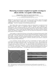
Fig. 6 (a) Schematic of a silic<strong>on</strong> <str<strong>on</strong>g>microdisk</str<strong>on</strong>g> EO modulator with selectively <str<strong>on</strong>g>integrated</str<strong>on</strong>g> depleti<strong>on</strong>-type Schottky diode. Inset: schematiccross-secti<strong>on</strong> of the Schottky diode. Al: aluminum. (b) FDTD-simulated TE-polarized mode-field profiles of a 1 st -order mode at thecoupling regi<strong>on</strong>. Our three-dimensi<strong>on</strong>al FDTD simulati<strong>on</strong>s assume a side-coupled waveguide width of 0.35 µm, a coupling gap of0.35 µm, <str<strong>on</strong>g>and</str<strong>on</strong>g> a <str<strong>on</strong>g>microdisk</str<strong>on</strong>g> diameter of 5 µm. wg: waveguide.Fig. 6(a) shows the schematic of our proposed design [36]. The inset shows the Schottky diode cross-secti<strong>on</strong> schematic.We adopt Schottky diode instead of the c<strong>on</strong>venti<strong>on</strong>al p-n diode because metal-semic<strong>on</strong>ductor juncti<strong>on</strong> has less parasiticseries resistance than p-n juncti<strong>on</strong>. Moreover, fewer processing steps are imposed as Schottky c<strong>on</strong>tact can be obtainedby depositing a metal film <strong>on</strong> the silic<strong>on</strong> wafer while defining the electrical c<strong>on</strong>tact patterns. The Schottky c<strong>on</strong>tact isformed <strong>on</strong> the slab regi<strong>on</strong> immediately outside the <str<strong>on</strong>g>microdisk</str<strong>on</strong>g> rim. The <str<strong>on</strong>g>microdisk</str<strong>on</strong>g> rim is p-typed slightly doped in orderto provide the necessary c<strong>on</strong>centrati<strong>on</strong> of depleted free-carriers up<strong>on</strong> reverse biasing the diode. As the diode is reversebiased,the majority carriers (h + ) in the <str<strong>on</strong>g>microdisk</str<strong>on</strong>g> rim regi<strong>on</strong> are swept out by the internal electric field. When the diodeis no l<strong>on</strong>ger biased, the majority carriers are swept back to neutralize the charges in the depleti<strong>on</strong> regi<strong>on</strong>. Thus, in eachmodulati<strong>on</strong> cycle, the free-carriers drift under the applied reverse bias or the internal electric field set by the depletedacceptor i<strong>on</strong>s. The absence of the slow injecti<strong>on</strong> carriers (transport by diffusi<strong>on</strong>) potentially offers high-speed opticalswitching. The <str<strong>on</strong>g>microdisk</str<strong>on</strong>g> central regi<strong>on</strong> is p-type highly doped in order to define the ohmic c<strong>on</strong>tact.In selectively embedding the Schottky diode, the <str<strong>on</strong>g>microdisk</str<strong>on</strong>g> p + -doped central regi<strong>on</strong> should be wide enough in order topreferentially suppress the higher-order WGMs, <str<strong>on</strong>g>and</str<strong>on</strong>g> in principle, <strong>on</strong>ly retain the 1 st -order WGM [37]. Whereas the<str<strong>on</strong>g>microdisk</str<strong>on</strong>g> rim should be narrow enough in order to reduce the parasitic resistance. Here we define the central dopedregi<strong>on</strong> relative radius r as the ratio of the p + -doped central regi<strong>on</strong> radius to the <str<strong>on</strong>g>microdisk</str<strong>on</strong>g> radius. Our simulati<strong>on</strong>s of a 5-µm-diameter <str<strong>on</strong>g>microdisk</str<strong>on</strong>g> suggest that we can adopt r = 0.68 (disk rim width = 0.8 µm) in order to preferentially suppressthe higher-order WGMs while retaining <strong>on</strong>ly the 1 st - order WGM. Fig. 6(b) shows the three-dimensi<strong>on</strong>al FDTDsimulatedcross-secti<strong>on</strong>al mode-field profiles at the coupling regi<strong>on</strong> of a 1 st -order WGM.Here we calculate the carrier c<strong>on</strong>centrati<strong>on</strong> variati<strong>on</strong>s in the <str<strong>on</strong>g>microdisk</str<strong>on</strong>g> rim regi<strong>on</strong> using a two-dimensi<strong>on</strong>alsemic<strong>on</strong>ductor device numerical simulati<strong>on</strong> tool MEDICI. We then compute the carrier-induced refractive index change∆n using the free-carrier plasma dispersi<strong>on</strong> formulae in silic<strong>on</strong> according to Soref <str<strong>on</strong>g>and</str<strong>on</strong>g> Bennett [26]. Fig. 7(a) shows thecalculated ∆n using 8 V reverse bias across the metal-rim separati<strong>on</strong>. We see that the smaller is the separati<strong>on</strong> (therebythe larger is the applied field), the larger is the ∆n. As a rule-of-thumb, in order to redshift a Q ~ 10 4 res<strong>on</strong>ance mode byabout a linewidth, we need a refractive index change of ~10 -4 . We choose the metal-rim separati<strong>on</strong> to be 0.4 µm whichprovides sufficient ∆n without imposing significant spatial overlap with the WGM field (see Fig. 6(b)). Fig. 7(b) showsthe calculated ∆n at various rim p-doping c<strong>on</strong>centrati<strong>on</strong>s (under 8-V reverse bias <str<strong>on</strong>g>and</str<strong>on</strong>g> 0.4-µm metal-rim separati<strong>on</strong>). Weobserve the maximum ∆n at rim p-doping c<strong>on</strong>centrati<strong>on</strong> of ~5x10 16 cm -3 .
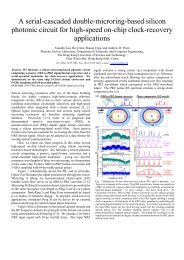
Fig. 7 (a) Calculated free-carrier induced refractive index change ∆n as a functi<strong>on</strong> of the metal-rim separati<strong>on</strong> up<strong>on</strong> 8-V reverse bias.Inset illustrates the metal-rim separati<strong>on</strong>. (b) Calculated ∆n as a functi<strong>on</strong> of p-doping c<strong>on</strong>centrati<strong>on</strong> in the <str<strong>on</strong>g>microdisk</str<strong>on</strong>g> rim. (c)Calculated ∆n temporal resp<strong>on</strong>se in the <str<strong>on</strong>g>microdisk</str<strong>on</strong>g> rim regi<strong>on</strong> (red) <str<strong>on</strong>g>and</str<strong>on</strong>g> in a (microring) waveguide (blue) from 0 V to -8 V <str<strong>on</strong>g>and</str<strong>on</strong>g> back to0 V. Inset: schematic cross-secti<strong>on</strong> of a (microring) waveguide with a laterally <str<strong>on</strong>g>integrated</str<strong>on</strong>g> Schottky diode of the same ohmic-to-Schottky separati<strong>on</strong> as in the <str<strong>on</strong>g>microdisk</str<strong>on</strong>g>. (d) Calculated ∆n rise <str<strong>on</strong>g>and</str<strong>on</strong>g> fall times as a functi<strong>on</strong> of the inner slab height (with fixed outerslab height at 0.03 µm). Inset illustrates the inner <str<strong>on</strong>g>and</str<strong>on</strong>g> outer slab heights. (e) Calculated ∆n rise <str<strong>on</strong>g>and</str<strong>on</strong>g> fall times as a functi<strong>on</strong> of theouter slab height (with fixed inner slab height at 0.21 µm).Fig. 7(c) shows the calculated ∆n temporal resp<strong>on</strong>se of a <str<strong>on</strong>g>microdisk</str<strong>on</strong>g> rim <str<strong>on</strong>g>and</str<strong>on</strong>g> a (microring) waveguide structure of thesame ohmic-to-Schottky separati<strong>on</strong> of 1.2 µm. Inset shows the waveguide cross secti<strong>on</strong>. The diode is revered-biasedfrom 0 V to -8 V <str<strong>on</strong>g>and</str<strong>on</strong>g> back to 0 V. The rise <str<strong>on</strong>g>and</str<strong>on</strong>g> fall times (~8 ps) of the <str<strong>on</strong>g>microdisk</str<strong>on</strong>g> are shorter than those of thewaveguide structure (23 ps – 14 ps). The electrical b<str<strong>on</strong>g>and</str<strong>on</strong>g>width of the Schottky diode is thus ~40 GHz. We attribute thefaster switching times of the <str<strong>on</strong>g>microdisk</str<strong>on</strong>g> than of the (microring) waveguide to the relatively low resistance provided by thelarger interface between the p + -doped central regi<strong>on</strong> <str<strong>on</strong>g>and</str<strong>on</strong>g> the <str<strong>on</strong>g>microdisk</str<strong>on</strong>g> rim regi<strong>on</strong>.In order to support the above argument, Fig. 7(d) shows the calculated ∆n rise <str<strong>on</strong>g>and</str<strong>on</strong>g> fall times at various inner slab heights(fixed outer slab height at 0.03 µm). Inset illustrates the inner <str<strong>on</strong>g>and</str<strong>on</strong>g> outer slab heights. An inner slab height of 0.21 µmcorresp<strong>on</strong>ds to the <str<strong>on</strong>g>microdisk</str<strong>on</strong>g> structure, whereas an inner slab height of 0.03 µm corresp<strong>on</strong>ds to the (microring)waveguide structure. The increase in the inner slab height increases the interface between the <str<strong>on</strong>g>microdisk</str<strong>on</strong>g> rim regi<strong>on</strong> <str<strong>on</strong>g>and</str<strong>on</strong>g>the p + -doped regi<strong>on</strong>, <str<strong>on</strong>g>and</str<strong>on</strong>g> thereby reduces the juncti<strong>on</strong> resistance. Fig. 7(c) shows the calculated ∆n rise <str<strong>on</strong>g>and</str<strong>on</strong>g> fall times atvarious outer slab heights. The effect of changing the outer slab height is less significant compared with varying theinner slab height because free-carriers (h + ) are swept in <str<strong>on</strong>g>and</str<strong>on</strong>g> out between the p + -doped central regi<strong>on</strong> <str<strong>on</strong>g>and</str<strong>on</strong>g> the p-doped rimregi<strong>on</strong> (but not via the Schottky c<strong>on</strong>tact).It should be emphasized that the b<str<strong>on</strong>g>and</str<strong>on</strong>g>width of a micro<str<strong>on</strong>g>res<strong>on</strong>ator</str<strong>on</strong>g>-based modulator is fundamentally limited by the phot<strong>on</strong>cavity lifetime τ as the res<strong>on</strong>ance mode needs time to build up <str<strong>on</strong>g>and</str<strong>on</strong>g> decay [36]. For a mode with Q ~ 10 4 , the decay time
can be estimated using the relati<strong>on</strong> Q = ωτ, where ω is the res<strong>on</strong>ance frequency. The estimated cavity lifetime is <strong>on</strong> theorder of 20 ps. Thus, the optical b<str<strong>on</strong>g>and</str<strong>on</strong>g>width of the proposed <str<strong>on</strong>g>microdisk</str<strong>on</strong>g> modulator can reach around 20 GHz (0.35/τ) <str<strong>on</strong>g>and</str<strong>on</strong>g>is fundamentally limited by the cavity lifetime.5. CONCLUSIONS AND FUTURE WORKIn summary, we reported our recent work <strong>on</strong> three silic<strong>on</strong> micro<str<strong>on</strong>g>res<strong>on</strong>ator</str<strong>on</strong>g> filters <str<strong>on</strong>g>and</str<strong>on</strong>g> modulators which can be relevantbuilding blocks to emergent applicati<strong>on</strong>-specific OEICs <strong>on</strong> silic<strong>on</strong> <strong>chip</strong>s. We experimentally investigated NRZ-to-PRZformat c<strong>on</strong>versi<strong>on</strong> using electrically tunable microring <str<strong>on</strong>g>res<strong>on</strong>ator</str<strong>on</strong>g>-based notch filters with laterally <str<strong>on</strong>g>integrated</str<strong>on</strong>g> p-i-n diodes.We showed that high-extincti<strong>on</strong>-ratio res<strong>on</strong>ances with critical coupling are essential in order to obtain pr<strong>on</strong>ouncedc<strong>on</strong>verted PRZ signals. We also experimentally dem<strong>on</strong>strated a silic<strong>on</strong> microring carrier-injecti<strong>on</strong>-type modulator with adouble-coupled U-bend waveguide as an external feedback. By applying a DC-bias either across the feedbackwaveguide or the microring, we dem<strong>on</strong>strated res<strong>on</strong>ance tuning with c<strong>on</strong>trolled extincti<strong>on</strong> ratio exceeding 10 dB at anoptimum bias voltage of the order of 1 V. Our initial experiments also suggested better modulator resp<strong>on</strong>se frommodulating the l<strong>on</strong>g U-bend feedback-waveguide than from modulating the short arcs of the microring. Lastly, wenumerically examined a silic<strong>on</strong> <str<strong>on</strong>g>microdisk</str<strong>on</strong>g> <str<strong>on</strong>g>res<strong>on</strong>ator</str<strong>on</strong>g>-based EO modulators using selectively embedded depleti<strong>on</strong>-typeSchottky diode that enables higher modulati<strong>on</strong> b<str<strong>on</strong>g>and</str<strong>on</strong>g>widths than c<strong>on</strong>venti<strong>on</strong>al injecti<strong>on</strong>-type diode. We showed that<str<strong>on</strong>g>microdisk</str<strong>on</strong>g> structures offer faster switching times (~8 ps) than microring structures. Our analysis further suggested thatour proposed device is fundamentally limited by the cavity lifetime which limits the optical b<str<strong>on</strong>g>and</str<strong>on</strong>g>width to around 20 GHz.In our <strong>on</strong>-going work, we seek to implement a silic<strong>on</strong> OEIC <strong>chip</strong> for clock recovery from high-data-rate NRZ signalsusing an <str<strong>on</strong>g>integrated</str<strong>on</strong>g> microring notch filter for NRZ-to-PRZ format c<strong>on</strong>versi<strong>on</strong> <str<strong>on</strong>g>and</str<strong>on</strong>g> a microring/<str<strong>on</strong>g>microdisk</str<strong>on</strong>g> EO modulator(injecti<strong>on</strong>-type or depleti<strong>on</strong>-type) driven by an external optoelectr<strong>on</strong>ic phase-locked loop as a phase comparator in orderto temporally gate the c<strong>on</strong>verted PRZ pulses. We envisi<strong>on</strong> that this kind of clock-recovery OEIC can find applicati<strong>on</strong>s inhigh-data-rate signal processing in fiber-optic networks [1], <str<strong>on</strong>g>and</str<strong>on</strong>g> also in optical interc<strong>on</strong>nects for Ultra-Short-Reachapplicati<strong>on</strong>s in computer <strong>chip</strong>s [3].ACKNOWLEDGEMENTSThis study was substantially supported by grants from the Research Grants Council of the H<strong>on</strong>g K<strong>on</strong>g SpecialAdministrative Regi<strong>on</strong>, China (projects HKUST6112/03E, HKUST6254/04E, & 618505).REFERENCES[1] P. Herve, <str<strong>on</strong>g>and</str<strong>on</strong>g> S. Ovadia, “Optical technologies for enterprise networks,” Intel. Technol. J. 8, 73 (2004).[2] D. A. B. Miller, “Rati<strong>on</strong>ale <str<strong>on</strong>g>and</str<strong>on</strong>g> challenges for optical interc<strong>on</strong>nects to electr<strong>on</strong>ic <strong>chip</strong>s,” Proc. IEEE 88, 728 (2000).[3] E. Mohammed, A. Alduino, T. Thomas, H. Braunisch, D. Lu, J. Heck, A. Liu, I. Young, B. Barnett, G. V<str<strong>on</strong>g>and</str<strong>on</strong>g>entop,<str<strong>on</strong>g>and</str<strong>on</strong>g> R. Mo<strong>on</strong>ey, “Optical interc<strong>on</strong>nect system integrati<strong>on</strong> for ultra short reach applicati<strong>on</strong>s,” Intel. Technol. J. 8,115 (2004).[4] L. Pavesi <str<strong>on</strong>g>and</str<strong>on</strong>g> G. Guillot, Optical Interc<strong>on</strong>nects: The Silic<strong>on</strong> Approach (Springer Series in Optical Sciences). NewYork: Springer, 2006.[5] E. Krioukov, D. J. W. Klunder, A. Driessen, J. Greve, <str<strong>on</strong>g>and</str<strong>on</strong>g> C. Otto, “Sensor based <strong>on</strong> an <str<strong>on</strong>g>integrated</str<strong>on</strong>g> opticalmicrocavity,” Opt. Lett. 27, 512 (2002).[6] N. M. Jokerst, M. A. Brooke, S. Cho, M. Thomas, J. Lillie, D. Kim, S. Ralph, <str<strong>on</strong>g>and</str<strong>on</strong>g> K. Dennis, “Integrated planarlightwave bio/chem. OEIC sensors <strong>on</strong> Si CMOS <str<strong>on</strong>g>circuits</str<strong>on</strong>g>,” Proc. SPIE 5730, 226 (2005).[7] J. Niehusmann, A. Vörckel, P. H. Bolivar, T. Wahlbrink, W. Henschel, <str<strong>on</strong>g>and</str<strong>on</strong>g> H. Kurz, “Ultrahigh-quality-factorsilic<strong>on</strong>-<strong>on</strong>-insulator microring <str<strong>on</strong>g>res<strong>on</strong>ator</str<strong>on</strong>g>,” Opt. Lett. 29, 2861 (2004).[8] I. Kiyat, A. Aydinli, <str<strong>on</strong>g>and</str<strong>on</strong>g> N. Dagli, “High-Q silic<strong>on</strong>-<strong>on</strong>-insulator optical rib waveguide racetrack <str<strong>on</strong>g>res<strong>on</strong>ator</str<strong>on</strong>g>s,” Opt.Express 13, 1900 (2005).[9] F. Xia, L. Sekaric, M. O’Boyle, <str<strong>on</strong>g>and</str<strong>on</strong>g> Y. Vlasov, “Coupled <str<strong>on</strong>g>res<strong>on</strong>ator</str<strong>on</strong>g> optical waveguides based <strong>on</strong> silic<strong>on</strong>-<strong>on</strong>insulatorphot<strong>on</strong>ic wires,” Appl. Phy. Lett. 89, 041122 (2006).[10] Q. Xu, S. S<str<strong>on</strong>g>and</str<strong>on</strong>g>hu, M. L. Povinelli, J. Shakya, S. Fan, <str<strong>on</strong>g>and</str<strong>on</strong>g> M. Lips<strong>on</strong>, “Experimental realizati<strong>on</strong> of an <strong>on</strong>-<strong>chip</strong> allopticalanalogue to electromagnetically induced transparency,” Phy. Rev. Lett. 96, 123901 (2006).
[11] M. A. Popović, T. Barwicz, M. R. Watts, P. T. Rakich, L. Socci, E. P. Ippen, F. X. Kärtner, <str<strong>on</strong>g>and</str<strong>on</strong>g> H. I. Smith,“Multistage high-order microring-<str<strong>on</strong>g>res<strong>on</strong>ator</str<strong>on</strong>g> add-drop filters,” Opt. Lett. 31, 2571 (2006).[12] A. Kazmierczak, M. Brière, E. Drouard, P. B<strong>on</strong>toux, P. Rojo-Romeo, I. O’C<strong>on</strong>nor, X. Letartre, F. Gaffiot, R.Orobtchouk, <str<strong>on</strong>g>and</str<strong>on</strong>g> T. Benyattou, “Design, simulati<strong>on</strong>, <str<strong>on</strong>g>and</str<strong>on</strong>g> characterizati<strong>on</strong> of a passive optical add-drop filter insilic<strong>on</strong>-<strong>on</strong>-insulator technology,” IEEE Phot<strong>on</strong>. Technol. Lett. 17, 1447 (2005)[13] P. Ko<strong>on</strong>ath, T. Indukuri, <str<strong>on</strong>g>and</str<strong>on</strong>g> B. Jalali, “M<strong>on</strong>olithic 3-D silic<strong>on</strong> phot<strong>on</strong>ics,” J. Lightwave Technol. 24, 1796, (2006).[14] N. Ma, C. Li, <str<strong>on</strong>g>and</str<strong>on</strong>g> A W. Po<strong>on</strong>, “Laterally coupled hexag<strong>on</strong>al micro-pillar <str<strong>on</strong>g>res<strong>on</strong>ator</str<strong>on</strong>g> add-drop filters in silic<strong>on</strong>nitride,” IEEE Phot<strong>on</strong>. Technol. Lett. 16, 2487 (2004).[15] C. Li, N. Ma, <str<strong>on</strong>g>and</str<strong>on</strong>g> A. W. Po<strong>on</strong>, “Waveguide-coupled octag<strong>on</strong>al <str<strong>on</strong>g>microdisk</str<strong>on</strong>g> channel add-drop filters,” Opt. Lett. 29,471 (2004).[16] C. Li <str<strong>on</strong>g>and</str<strong>on</strong>g> A. W. Po<strong>on</strong>, “Experimental dem<strong>on</strong>strati<strong>on</strong> of waveguide-coupled round-cornered octag<strong>on</strong>almicro<str<strong>on</strong>g>res<strong>on</strong>ator</str<strong>on</strong>g>s in silic<strong>on</strong> nitride”, Opt. Lett. 30, 546 (2005).[17] C. Li, L. Zhou, S. Zheng, <str<strong>on</strong>g>and</str<strong>on</strong>g> A. W. Po<strong>on</strong>, “Silic<strong>on</strong> polyg<strong>on</strong>al <str<strong>on</strong>g>microdisk</str<strong>on</strong>g> <str<strong>on</strong>g>res<strong>on</strong>ator</str<strong>on</strong>g>s,” IEEE J. Sel. Topics QuantumElectr<strong>on</strong>. (special issue <strong>on</strong> silic<strong>on</strong> phot<strong>on</strong>ics) 12, 1438 (2006).[18] J. Y. Lee <str<strong>on</strong>g>and</str<strong>on</strong>g> A. W. Po<strong>on</strong>, “Spiral micropillar <str<strong>on</strong>g>res<strong>on</strong>ator</str<strong>on</strong>g>-based unidirecti<strong>on</strong>al channel drop filters,” in Proc. 8thInternati<strong>on</strong>al C<strong>on</strong>ference <strong>on</strong> Transparent Optical Networks, Nottingham, UK, c<strong>on</strong>ference proceedings, 1, pp. 62-65, 2006.[19] J. Y. Lee <str<strong>on</strong>g>and</str<strong>on</strong>g> A. W. Po<strong>on</strong>, “Spiral-shaped <str<strong>on</strong>g>microdisk</str<strong>on</strong>g> <str<strong>on</strong>g>res<strong>on</strong>ator</str<strong>on</strong>g>-based channel drop filters <strong>on</strong> a silic<strong>on</strong> nitride <strong>chip</strong>,”in proceedings of IEEE 3rd Internati<strong>on</strong>al C<strong>on</strong>ference <strong>on</strong> Group IV Phot<strong>on</strong>ics, Ottawa, ON, Canada, pp. 19-21,2006.[20] I. Kiyat, A. Aydinli, <str<strong>on</strong>g>and</str<strong>on</strong>g> N. Dagli, “Low-power thermooptical tuning of SOI <str<strong>on</strong>g>res<strong>on</strong>ator</str<strong>on</strong>g> switch,” IEEE Phot<strong>on</strong>.Technol. Lett. 18, 364 (2006).[21] G. N. Niels<strong>on</strong>, D. Seneviratne, F. Lopez-Royo, P. T. Rakich, Y. Avrahami, M. R. Watts, H. A. Haus, H. L. Tuller,<str<strong>on</strong>g>and</str<strong>on</strong>g> G. Barbastathis, “Integrated wavelength-selective optical MEMS switching using ring <str<strong>on</strong>g>res<strong>on</strong>ator</str<strong>on</strong>g> filters,” IEEEPhot<strong>on</strong>. Technol. Lett. 17, 1190 (2005).[22] V. R. Almeida, C. A. Barrios, R. R. Panepucci, <str<strong>on</strong>g>and</str<strong>on</strong>g> M. Lips<strong>on</strong>, “All-optical c<strong>on</strong>trol of light <strong>on</strong> a silic<strong>on</strong> <strong>chip</strong>,”Nature 431, 1081 (2004).[23] Q. Xu, B. Shmidt, S. Pradhan, <str<strong>on</strong>g>and</str<strong>on</strong>g> M. Lips<strong>on</strong>, “Micrometre-scale silic<strong>on</strong> electro-optic modulator,” Nature 435, 325(2005).[24] Q. Xu, B. Schmidt, J. Shakya, <str<strong>on</strong>g>and</str<strong>on</strong>g> M. Lips<strong>on</strong>, “Cascaded silic<strong>on</strong> micro-ring modulators for WDM opticalinterc<strong>on</strong>necti<strong>on</strong>,” Opt. Express 14, 9430 (2006).[25] C. Gunn, “CMOS phot<strong>on</strong>ics technology platform”, invited paper 6125-01, SPIE Phot<strong>on</strong>ics West, SPIE Proceedingsvol. 6125 <strong>on</strong> Silic<strong>on</strong> Phot<strong>on</strong>ics, San Jose, CA, 25 Jan 2006.[26] R. A. Soref <str<strong>on</strong>g>and</str<strong>on</strong>g> B. R. Bennett, “Electrooptical effects in silic<strong>on</strong>,” IEEE J. Quantum Electr<strong>on</strong>. QE-23, 123 (1987).[27] L. Zhou <str<strong>on</strong>g>and</str<strong>on</strong>g> A. W. Po<strong>on</strong>, “Silic<strong>on</strong> electro-optic modulators using p-i-n diodes embedded 10-micr<strong>on</strong>-diameter<str<strong>on</strong>g>microdisk</str<strong>on</strong>g> <str<strong>on</strong>g>res<strong>on</strong>ator</str<strong>on</strong>g>s,” Opt. Express 14, 6851 (2006).[28] G. P. Agrawal: Fiber-optic communicati<strong>on</strong> systems (3 rd editi<strong>on</strong>). New York: Wiley, 2004.[29] X. Li, C. Kim, <str<strong>on</strong>g>and</str<strong>on</strong>g> G. Li, “All-optical passive clock extracti<strong>on</strong> of 40 Gbit/s NRZ data using narrow-b<str<strong>on</strong>g>and</str<strong>on</strong>g> filtering,”Opt. Express 12, 3196 (2004).[30] C.-H. Lee <str<strong>on</strong>g>and</str<strong>on</strong>g> H. K. Lee, “Passive all-optical clock signal extractor for n<strong>on</strong>-return-to-zero signals,” Electr<strong>on</strong>. Lett.34, 295 (1998).[31] A. Reale, P. Lugli, <str<strong>on</strong>g>and</str<strong>on</strong>g> S. Betti, “Format c<strong>on</strong>versi<strong>on</strong> of optical data using four-wave mixing in semic<strong>on</strong>ductoroptical amplifiers,” IEEE J. Sel. Topics Quantum Electr<strong>on</strong>. 7, 703 (2001).[32] J. Slovak, C. Bornholdt, J. Kreissl, S. Bauer, M. Biletzke, M. Schlak, <str<strong>on</strong>g>and</str<strong>on</strong>g> B. Sartorius, “Bit rate <str<strong>on</strong>g>and</str<strong>on</strong>g> wavelengthtransparent all-optical clock recovery scheme for NRZ-coded PRBS signals,” IEEE Phot<strong>on</strong>. Technol. Lett. 18, 844(2006).[33] J. Yu, G. K. Chang, J. Barry, <str<strong>on</strong>g>and</str<strong>on</strong>g> Y. Su, “40 Gbit/s signal format c<strong>on</strong>versi<strong>on</strong> from NRZ to RZ using a Mach-Zehnder delay interferometer,” Opt. Communicati<strong>on</strong>s 248, 419 (2004).[34] L. Zhou, H. Chen <str<strong>on</strong>g>and</str<strong>on</strong>g> A. W. Po<strong>on</strong>, “NRZ-to-PRZ format c<strong>on</strong>verters using narrowb<str<strong>on</strong>g>and</str<strong>on</strong>g> 10-GHz-b<str<strong>on</strong>g>and</str<strong>on</strong>g>widthmicro<str<strong>on</strong>g>res<strong>on</strong>ator</str<strong>on</strong>g>-based notch filters,” manuscript submitted to C<strong>on</strong>ference <strong>on</strong> Lasers Electro-Optics, Baltimore,Maryl<str<strong>on</strong>g>and</str<strong>on</strong>g>, May 7-12, 2007.[35] L. Zhou <str<strong>on</strong>g>and</str<strong>on</strong>g> A. W. Po<strong>on</strong>, “Silic<strong>on</strong> electro-optics switches using microring <str<strong>on</strong>g>res<strong>on</strong>ator</str<strong>on</strong>g>s with phase-tunablefeedback,” in proceedings of IEEE/LEOS 3 rd Internati<strong>on</strong>al C<strong>on</strong>ference <strong>on</strong> Group IV Phot<strong>on</strong>ics, Ottawa, Canada,Sep. 13-15, 2006.
[36] N. K. H<strong>on</strong>, L. Zhou <str<strong>on</strong>g>and</str<strong>on</strong>g> A.W. Po<strong>on</strong>, “Silic<strong>on</strong> depleti<strong>on</strong>-type <str<strong>on</strong>g>microdisk</str<strong>on</strong>g> electro-optic modulators using selectively<str<strong>on</strong>g>integrated</str<strong>on</strong>g> Schottky diodes” manuscript submitted to C<strong>on</strong>ference <strong>on</strong> Lasers Electro-Optics, Baltimore, Maryl<str<strong>on</strong>g>and</str<strong>on</strong>g>,May 7-12, 2007.[37] L. Zhou <str<strong>on</strong>g>and</str<strong>on</strong>g> A. W. Po<strong>on</strong>, “Silic<strong>on</strong>-<strong>on</strong>-insulator tunable waveguide-coupled <str<strong>on</strong>g>microdisk</str<strong>on</strong>g> <str<strong>on</strong>g>res<strong>on</strong>ator</str<strong>on</strong>g>s with selectively<str<strong>on</strong>g>integrated</str<strong>on</strong>g> p-i-n diodes” in proceedings of C<strong>on</strong>ference <strong>on</strong> Lasers <str<strong>on</strong>g>and</str<strong>on</strong>g> Electro-Optics, Baltimore, Maryl<str<strong>on</strong>g>and</str<strong>on</strong>g>, May22-27 2005.