
Create successful ePaper yourself
Turn your PDF publications into a flip-book with our unique Google optimized e-Paper software.
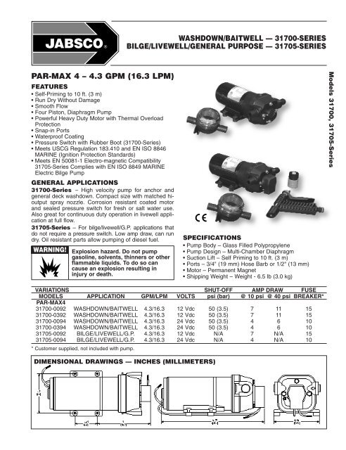
WASHDOWN/BAITWELL — 31700-SERIESBILGE/LIVEWELL/GENERAL PURPOSE — 31705-SERIESPAR-MAX 4 – 4.3 GPM (16.3 LPM)FEATURES• Self-Priming to 10 ft. (3 m)• Run Dry Without Damage• Smooth Flow• Four Piston, Diaphragm Pump• Powerful Heavy Duty Motor with Thermal OverloadProtection• Snap-in Ports• Waterproof Coating• Pressure Switch with Rubber Boot (31700-Series)• Meets USCG Regulation 183.410 and EN ISO 8846MARINE (Ignition Protection Standards)• Meets EN 50081-1 Electro-magnetic Compatibility31705-Series Complies with EN ISO 8849 MARINEElectric Bilge PumpGENERAL APPLICATIONS31700-Series – High velocity pump for anchor andgeneral deck washdown. Compact size with matched hioutputspray nozzle. Corrosion resistant coated motorand sealed pressure switch for fresh or salt water use.Also great for continuous duty operation in livewell applicationat full flow.31705-Series – For bilge/livewell/G.P. applications thatdo not require a pressure switch. Low amp draw, can rundry. Oil resistant parts allow pumping of diesel fuel.WARNING!Explosion hazard. Do not pumpgasoline, solvents, thinners or otherflammable liquids. To do so cancause an explosion resulting ininjury or death.SPECIFICATIONS• Pump Body – Glass Filled Polypropylene• Pump Design – Multi-Chamber Diaphragm• Suction Lift – Self Priming to 10 ft. (3 m)• Ports – 3/4" (19 mm) Hose Barb or 1/2" (13 mm)• Motor – Permanent Magnet• Shipping Weight – Weight - 6.5 lb (3.0 kg)Models 31700, 31705-SeriesVARIATIONSMODELSPAR-MAX431700-009231700-039231700-009431700-039431705-009231705-0094APPLICATIONWASHDOWN/BAITWELLWASHDOWN/BAITWELLWASHDOWN/BAITWELLWASHDOWN/BAITWELLBILGE/LIVEWELL/G.P.BILGE/LIVEWELL/G.P.GPM/LPM4.3/16.34.3/16.34.3/16.34.3/16.34.3/16.34.3/16.3VOLTS12 Vdc12 Vdc24 Vdc24 Vdc12 Vdc24 VdcSHUT-OFFpsi (bar)50 (3.5)50 (3.5)50 (3.5)50 (3.5)N/AN/AAMP DRAW@ 10 psi @ 40 psi774474111166N/AN/AFUSEBREAKER*151510101510* Customer supplied, not included with pump.DIMENSIONAL DRAWINGS — INCHES (MILLIMETERS)
INSTALLATIONSFig. 131700-SeriesFig. 231700-Series w/Rule ® Dual PortFig. 331705-SeriesQuick Easy InstallationVersatile Snap-in PortsMOUNTINGThe PAR-MAX pumps are self-priming and may be locatedabove or below the fresh water supply in a dry location.To vertically mount these units, it is best to do so withthe motor on top. This will prevent water dripping onmotor in the event of a leak. Place pump on a solid surfaceand secure with the four mounting screws beingcareful not to compress the rubber grommets which actas shock absorbers.PLUMBINGIT IS RECOMMENDED THAT MARINE GRADEREINFORCED HOSE BE USED FOR ALL PLUMBINGWITH THESE MODELS OF PAR-MAX PUMPS.31700-Series – Washdown/Livewell (Fig. 1)Install the Pumpgard strainer (provided) to the hose fromthe water source (thru-hull seacock or water tank).Connect the Pumpgard strainer to the pump inlet port.Connect the pump discharge to a 3-way valve or T (if livewellhas a shutoff valve). Connect to livewell and to hosebib. From hose bib use new spray nozzle.31700-Series – w/Rule ® Dual Port (Fig. 2)Install Rule ® dual port pump to seacock. Connect hosefrom dual port pump to livewell/baitwell tank (see Fig. 2).Connect washdown hose from dual port pump toPumpguard strainer, connect to pump inlet port. Connecthose from pump outlet to pressure nozzle.31705-Series – Bilge/Livewell (Fig. 3)The 31705-Series pumps can be used as either a bilgepump or as a bait tank/livewell pump. Connect from bilgeto Pumpgard strainer (provided) to pump to discharge. Orfrom thru-hull seacock to Pumpgard to pump to tank.Note – Pumpgard strainers should be mounted in themost accessible place possible to make periodic cleaningof the screen easier.The electrical circuit should be protected with an overcurrentprotection device in the positive lead. See chartfor proper size. The pump circuit should not include anyother electrical loads. The open terminal on the pressureswitch is positive. Black wire from the motor is negative.Select wire size from chart below. Use total length of wirefrom the battery to pump and return. Chart allows for 3%voltage drop. If in doubt, use next larger wire size.If you are not familiar with applicable electrical standards,have the unit installed by a qualified electrician.After installation, check the voltage at the pump motor.Voltage should be checked when pump is operating. Fullvoltage must be available at the pump motor at all times.Total lengthin feet12 Volt24 VoltOPERATION0-20(0-6 m)#14 AWG(2.5 mm 2 )#16 AWG(1.5 mm 2 )20-35(6-11 m)#12 AWG(4 mm 2 )#14 AWG(2.5 mm 2 )35-55(11-17 m)#10 AWG(6 mm 2 )#12 AWG(4 mm 2 )1. Open seacock (washdown or livewell applications).2. Open hose bib and/or spray nozzle (31700-Series) ormake sure discharge thru-hull is clear (31705-Series).3. Turn on pump.4. 31700-Series. Close spray nozzle/hose bib whenwater runs free of air. Pump is now ready for automaticdemand operation.5. 31705-Series. Pumps do not have a pressure switchand are usually switched manually.6. For prolonged operation, pump must operate at fullopen flow.WIRINGIn an easily accessible location, install a switch to controlelectricity to the pump. The switch should have an amprating equal to or greater than the fuse size specified forthe pump. Turn the pump off when not used for extendedperiods or when the tank is empty.CAUTION!Motor case will get hot.Prolonged contact during operationmay cause a burn.
WARNING: DISCONNECT POWER TO PUMP AND OPEN VALVE TORELIEVE WATER PRESSURE PRIOR TO SERVICING PUMPEXPLODED VIEW* Service kit includes Keys 2, 3 and 4B, C, D and 8KEYDESCRIPTIONQTY111111111111131705-SERIES — PART NO.12345*6*789Upper HousingValve KitDiaphragm KitLower Housing KitPressure SwitchService KitMotor Kit – 12V EMC COMP24V EMC COMPSlide ClipsPumphead Assy.Pumpgard StrainerSpray Nozzle USSpray Nozzle EC18910-400018911-701018912-305018915-9005N.A.18920-905318919-014018919-106230648-100018914-630046400-000031700-SERIES — PART NO.18910-405018911-703018912-304018915-900218916-005018920-904318919-014018919-106230648-100018914-635046400-000030703-100030704-1000DISASSEMBLEPressure Switch (5)1. Disconnect power to pump and open a faucet or valve to relievesystem pressure.2. Remove Rubber Boot, then remove the two visible PressureSwitch Screws located on each side of the Pressure Switch (5).Upper Housing (1)3. Slide Port Clip (8) back and unplug from Tank Plumbing.4. Loosen but DO NOT remove the four Pump Head Screws andcarefully remove Upper Housing Assembly (1).5. Remove Check Valve (2) and inspect for debris.Check Valve Assembly (2) Follow Steps 1, 3 & 46. Inspect Check Valve (2) and O-RingLower Housing (4) Follow Step 1, 3 & 47. Remove Rubber Plugs on housing (4-A) to access Allen Screw.8. Rotate Lower Housing (4), so access notch is aligned with CamBearing Set Screw (4-C), loosen set screw with a 1/8" AllenWrench and slide pump head off motor shaft.Diaphragm (3-B)9. Loosen four cam piston screws with Phillips head screw driverand pull apart cam (4-B) from Inner Pistons (3-A). (Both pistons(3-A & C) should be replaced when a new Diaphragm (3-B) isinstalled.)Motor (7) Follow steps 1, 3, 4, 7, & 8REASSEMBLEDiaphragm (3-B)1. Insert Outer Pistons (3-C) into Lower Housing (4-A) by bending pistonsat center fold.2. Placing the Diaphragm (3-B) (flatter side of Diaphragm facing themotor) on the Lower housing (4-A). Press each Inner Piston (3-A)through the Diaphragm and Lower Housing (4A) into Outer Piston(3-C). Hex stem of Inner Pistons (3-A) must be aligned into hex holesin Outer Pistons (3-C). Tighten cam piston screws partially, center pistonin diaphragm, and tighten screws securely (18 in. lbs. torque). Also,the Outer Pistons (3-C) must be aligned with alignment slots on CamAssembly (4-B) making sure screw holes align in cam assembly, otherwisediaphragm will leak.Cam Bearing (4-B)3. Place Cam Bearing (4-B) over Inner Pistons (3-C) and tightendown with four Phillips Head Screws. (18 in. lbs. torque)Lower Housing (4) to Motor (7)Coat motor shaft with grease prior to installing Cam Bearing (4-B).4. When installing the Lower Housing (4), rotate access notch to alignwith Cam Bearing Set Screw (4-C).5. Attach Cam Bearing (4-B) to motor shaft indentation with Cam BearingSet Screw (4-C). (35 in. lbs. torque)6. Reinsert new Notch Plugs.Check Valve (2)7. Place Ferrules (Rubber Cones) in the Upper Housing (1) coned sidefirst.8. Properly seat O-Ring in Check Valve (2) and insert Check Valve (2)into the Upper Housing (1).Upper Housing (1)9. Place Upper Housing (1) on top of the Lower Housing (4-A) and tightenHex Bolts (30 in. lbs. torque) through the Upper Housing (1) to theMotor.
TROUBLESHOOTINGSymptomPump will not prime or retainprime after operatingPump runs but no fluidMotor runs too hotFlow rate is lowPossible Cause(s)1. Air leak in suction line2. Defective valve (Key 2)3. Upper housing leaking (Key 1)4. Suction lift too high5. Debris in valve(s) (Key 2)1. Faulty suction piping2. Defective valve (Key 2)3. Suction lift too high4. Clogged inlet5. Inlet line valve closed1. Voltage incorrect2. Insufficient ventilation for motor1. Piping or hose is damaged2. Clogged valve (Key 2)3. Worn valve (Key 2)4. Voltage incorrect5. Tank over pressurizedPump leaks 1. Upper housing loose (Key 1)2. Pistons loose (Key 3A, 3C)3. Pump head loose on motor4. Switch loose (Key 5)5. Defective Diaphragm (Key 3B)Pump will not run1. No electricity2. Defective pressure switch (Key 5)3. Motor has open circuit (Key 7)4. Thermal protector has cut off (Key 7)Corrective Action1. Repair or replace2. Replace3. Tighten bolts4. Lower pump5. Clean valve(s)1. Repair or replace2. Replace3. Lower pump4. Clean or replace5. Open valve1. Check voltage2. Insure proper ventilation1. Clean or replace2. Clear obstruction3. Replace4. Check voltage5. Check tank pressure1. Tighten screws2. Tighten pistons3. Tighten pump head4. Tighten switch5. Replace1. Check connections, fuse, breakers2. Replace switch3. Replace4. Allow motor to cool 14-30 min.CONVERSION TABLETO CONVERTGallons, U.S.LitersPounds/Sq. <strong>Inc</strong>hBarFahrenheitCelsiusACCESSORIESSNAP-IN PORT SYSTEMTOLitersGallons, U.S.BarPounds/Sq. <strong>Inc</strong>hCelsiusFahrenheitMULTIPLY BY3.7850.2640.06914.5( ˚F-32) .556( ˚C X 1.8) + 32NOTE:Use 306XX-1000 Series EPDM forpotable water.Use 306XX-1001 Series Buna foroil or diesel fuel.THE PRODUCTS DESCRIBED HEREIN ARESUBJECT TO THE JABSCO ONE YEAR LIMITEDWARRANTY, WHICH IS AVAILABLE FOR YOURINSPECTION UPON REQUEST.U.S.A.Jabsco20 IconFoothill Ranch, CA 92610-3000Tel: 949.609.5106Fax: 949.859.1254UNITED KINGDOMJabscoBingley Road, HoddesdonHertfordsire EN11 OBUTel: +44 (0) 1992 450145Fax: +44 (0) 1992 467132CANADAFluid Products Canada55 Royal RoadGuelph, Ontario N1H 1T1Tel: (519) 821.1900Fax: (519) 821.2569JAPANNHK Jabsco Company Ltd.3-21-10, Shin-YokohamaKohoku-Ku, Yokohama, 222Tel: 045.475.8906Fax: 045.475.8908GERMANYJabsco GmbHOststrasse 2822840 NorderstedtTel: +49-40-53 43 73 -0Fax: +49-40-53 53 73 -11© Copyright 2002, ITT Industries Printed in U.S.A. All Rights Reserved Form: 43000-0754 Rev. 10/2002