Impact of Feedback Delay on Closed-Loop Stability - System Control ...
Impact of Feedback Delay on Closed-Loop Stability - System Control ...
Impact of Feedback Delay on Closed-Loop Stability - System Control ...

Create successful ePaper yourself
Turn your PDF publications into a flip-book with our unique Google optimized e-Paper software.
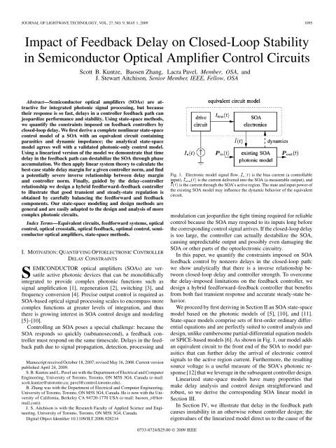
JOURNAL OF LIGHTWAVE TECHNOLOGY, VOL. 27, NO. 9, MAY 1, 2009 1095<str<strong>on</strong>g>Impact</str<strong>on</strong>g> <str<strong>on</strong>g>of</str<strong>on</strong>g> <str<strong>on</strong>g>Feedback</str<strong>on</strong>g> <str<strong>on</strong>g>Delay</str<strong>on</strong>g> <strong>on</strong> <strong>Closed</strong>-<strong>Loop</strong> <strong>Stability</strong>in Semic<strong>on</strong>ductor Optical Amplifier C<strong>on</strong>trol CircuitsScott B. Kuntze, Baosen Zhang, Lacra Pavel, Member, OSA, andJ. Stewart Aitchis<strong>on</strong>, Senior Member, IEEE, Fellow, OSAAbstract—Semic<strong>on</strong>ductor optical amplifiers (SOAs) are attractivefor integrated phot<strong>on</strong>ic signal processing, but becausetheir resp<strong>on</strong>se is so fast, delays in a c<strong>on</strong>troller feedback path canjeopardize performance and stability. Using state-space methods,we quantify the c<strong>on</strong>straints imposed <strong>on</strong> feedback c<strong>on</strong>trollers byclosed-loop delay. We first derive a complete n<strong>on</strong>linear state-spacec<strong>on</strong>trol model <str<strong>on</strong>g>of</str<strong>on</strong>g> a SOA with an equivalent circuit c<strong>on</strong>tainingparasitics and dynamic impedance; the analytical state-spacemodel agrees well with a validated phot<strong>on</strong>ic-<strong>on</strong>ly c<strong>on</strong>trol model.Using a linearized versi<strong>on</strong> <str<strong>on</strong>g>of</str<strong>on</strong>g> the model we dem<strong>on</strong>strate that timedelay in the feedback path can destabilize the SOA through phaseaccumulati<strong>on</strong>. We then apply linear system theory to calculate thebest-case stable delay margin for a given c<strong>on</strong>troller norm, and finda potentially severe inverse relati<strong>on</strong>ship between delay marginand c<strong>on</strong>troller norm. Finally, guided by the delay–c<strong>on</strong>trollerrelati<strong>on</strong>ship we design a hybrid feedforward–feedback c<strong>on</strong>trollerto illustrate that good transient and steady-state regulati<strong>on</strong> isobtained by carefully balancing the feedforward and feedbackcomp<strong>on</strong>ents. Our state-space modeling and design methods aregeneral and are easily adapted to the design and analysis <str<strong>on</strong>g>of</str<strong>on</strong>g> morecomplex phot<strong>on</strong>ic circuits.Index Terms—Equivalent circuits, feedforward systems, opticalc<strong>on</strong>trol, optical crosstalk, optical feedback, optimal c<strong>on</strong>trol, semic<strong>on</strong>ductoroptical amplifiers, state-space methods.I. MOTIVATION:QUANTIFYING OPTOELECTRONIC CONTROLLERDELAY CONSTRAINTSSEMICONDUCTOR optical amplifiers (SOAs) are versatileactive phot<strong>on</strong>ic devices that can be m<strong>on</strong>olithicallyintegrated to provide complex phot<strong>on</strong>ic functi<strong>on</strong>s such assignal amplificati<strong>on</strong> [1], regenerati<strong>on</strong> [2], switching [3], andfrequency c<strong>on</strong>versi<strong>on</strong> [4]. Precise output c<strong>on</strong>trol is required asSOA-based optical signal processing scales to encompass morecomplex functi<strong>on</strong>s at greater levels <str<strong>on</strong>g>of</str<strong>on</strong>g> integrati<strong>on</strong>, and thusthere is growing interest in SOA c<strong>on</strong>trol design and modeling[5]–[10].C<strong>on</strong>trolling an SOA poses a special challenge: because theSOA resp<strong>on</strong>ds so quickly (subnanosec<strong>on</strong>d), a feedback c<strong>on</strong>trollermust resp<strong>on</strong>d <strong>on</strong> the same timescale. <str<strong>on</strong>g>Delay</str<strong>on</strong>g>s in the feedbackpath due to signal propagati<strong>on</strong>, detecti<strong>on</strong>, processing andManuscript received October 18, 2007; revised May 16, 2008. Current versi<strong>on</strong>published April 24, 2009.S. B. Kuntze and L. Pavel are with the Department <str<strong>on</strong>g>of</str<strong>on</strong>g> Electrical and ComputerEngineering, University <str<strong>on</strong>g>of</str<strong>on</strong>g> Tor<strong>on</strong>to, Tor<strong>on</strong>to, ON M5S 3G4, Canada (e-mail:scott.kuntze@utor<strong>on</strong>to.ca; pavel@c<strong>on</strong>trol.tor<strong>on</strong>to.edu).B. Zhang was with the Department <str<strong>on</strong>g>of</str<strong>on</strong>g> Electrical and Computer Engineering,University <str<strong>on</strong>g>of</str<strong>on</strong>g> Tor<strong>on</strong>to, Tor<strong>on</strong>to, ON M5S 3G4, Canada. He is now with the University<str<strong>on</strong>g>of</str<strong>on</strong>g> California, Berkeley CA 94720-1770 USA (e-mail: baosen_z@hotmail.com).J. S. Aitchis<strong>on</strong> is with the Research Faculty <str<strong>on</strong>g>of</str<strong>on</strong>g> Applied Science and Engineering,University <str<strong>on</strong>g>of</str<strong>on</strong>g> Tor<strong>on</strong>to, Tor<strong>on</strong>to, ON M5S 3G4, Canada.Digital Object Identifier 10.1109/JLT.2008.928214Fig. 1. Electr<strong>on</strong>ic model signal flow. I (t) is the bias current (a c<strong>on</strong>trollableinput), I (t) is the current delivered into the SOA (a measurable output), andI(t) is the current through the SOA’s active regi<strong>on</strong>. The state and input power <str<strong>on</strong>g>of</str<strong>on</strong>g>the existing SOA model may influence the dynamic behavior <str<strong>on</strong>g>of</str<strong>on</strong>g> the equivalentcircuit.modulati<strong>on</strong> can jeopardize the tight timing required for reliablec<strong>on</strong>trol because the SOA may resp<strong>on</strong>d to its inputs l<strong>on</strong>g beforethe corresp<strong>on</strong>ding c<strong>on</strong>trol signal arrives. If the closed-loop delayis too large, the c<strong>on</strong>troller can actually destabilize the SOA,causing unpredictable output and possibly even damaging theSOA or other parts <str<strong>on</strong>g>of</str<strong>on</strong>g> the optoelectr<strong>on</strong>ic circuitry.In this paper, we quantify the c<strong>on</strong>straints imposed <strong>on</strong> SOAfeedback c<strong>on</strong>trol by n<strong>on</strong>zero delays in the closed-loop path:we show analytically that there is a inverse relati<strong>on</strong>ship betweenclosed-loop delay and c<strong>on</strong>troller strength. To overcomethe delay-imposed limitati<strong>on</strong>s <strong>on</strong> the feedback c<strong>on</strong>troller, wedesign a hybrid feedforward–feedback c<strong>on</strong>troller that benefitsfrom both fast transient resp<strong>on</strong>se and accurate steady-state behavior.We proceed by first deriving in Secti<strong>on</strong> II an SOA state-spacemodel based <strong>on</strong> the phot<strong>on</strong>ic models <str<strong>on</strong>g>of</str<strong>on</strong>g> [5], [10], and [11].State-space models comprise sets <str<strong>on</strong>g>of</str<strong>on</strong>g> first-order ordinary differentialequati<strong>on</strong>s and are perfectly suited to c<strong>on</strong>trol analysis anddesign, unlike cumbersome partial-differential equati<strong>on</strong> modelsor SPICE-based models [6]. As shown in Fig. 1, our model addsan equivalent circuit to the fr<strong>on</strong>t end <str<strong>on</strong>g>of</str<strong>on</strong>g> the SOA to model parasiticsthat can further delay the arrival <str<strong>on</strong>g>of</str<strong>on</strong>g> electr<strong>on</strong>ic c<strong>on</strong>trolsignals to the active regi<strong>on</strong> current. Furthermore, the resultingsource voltage is a useful measure <str<strong>on</strong>g>of</str<strong>on</strong>g> the SOA’s phot<strong>on</strong>ic resp<strong>on</strong>se[12] that we leverage in the subsequent c<strong>on</strong>troller design.Linearized state-space models have many properties thatmake delay analysis and c<strong>on</strong>trol design straightforward androbust, so we derive the corresp<strong>on</strong>ding SOA linear model inSecti<strong>on</strong> III.In Secti<strong>on</strong> IV, we illustrate that delay in the feedback pathcauses instability in an otherwise robust c<strong>on</strong>troller design; theeigenvalues <str<strong>on</strong>g>of</str<strong>on</strong>g> the linearized model direct us to the cause <str<strong>on</strong>g>of</str<strong>on</strong>g> the0733-8724/$25.00 © 2009 IEEE
1100 JOURNAL OF LIGHTWAVE TECHNOLOGY, VOL. 27, NO. 9, MAY 1, 2009The coefficients and relate the state and inputto the output . has rows and four columns;is square with dimensi<strong>on</strong> . Both are sparse, withdiag<strong>on</strong>al. If the electr<strong>on</strong>ic output is taken to be in Fig. 2,we have(25a)(25b)Fig. 4. <str<strong>on</strong>g>Feedback</str<strong>on</strong>g> <str<strong>on</strong>g>of</str<strong>on</strong>g> the SOA state N (t) into the drive current I (t) to suppresscrosstalk between optical channels P (t) as in [5].if the electr<strong>on</strong>ic output is instead,wehave(26a)(26b)Regardless, the remaining n<strong>on</strong>zero entries are given byand(27a)(27b)Fig. 5. Relative parametric phase portraits <str<strong>on</strong>g>of</str<strong>on</strong>g> the static augmented system(F;G; H;J ) under state feedback into the bias current from N (t) <strong>on</strong>ly; theflow <str<strong>on</strong>g>of</str<strong>on</strong>g> time is indicated by the arrows. The system—excited by a 13% stepmodulati<strong>on</strong> in optical power for 2 ns—is unstable, spiraling ever outward untildevice failure.(28a)(28b)where again all the derivatives are found in the appendix and areevaluated at the equilibria .Referring back to Fig. 3, there is good qualitative agreementbetween the n<strong>on</strong>linear (dashed line) and linear (solid line)equivalent circuit models. For input modulati<strong>on</strong>s typicallygreater than 20%, there is some qualitative separati<strong>on</strong> betweenthe linear and n<strong>on</strong>linear models; for a given applicati<strong>on</strong> it isthe designer’s choice how much error is acceptable, althoughthe c<strong>on</strong>troller can be designed to switch between several precomputedoperating points to lessen discrepancies. We show inSecti<strong>on</strong> VI that a c<strong>on</strong>troller designed at a single operating pointworks well even with 100% optical modulati<strong>on</strong>s.IV. STATE FEEDBACK INTO THE DRIVE CURRENT ANDSYSTEM STABILITYState feedback provides the most effective c<strong>on</strong>trol because thestate c<strong>on</strong>tains all the current informati<strong>on</strong> <str<strong>on</strong>g>of</str<strong>on</strong>g> the system. In thissecti<strong>on</strong> we isolate a source <str<strong>on</strong>g>of</str<strong>on</strong>g> closed-loop instability by comparingstate feedback c<strong>on</strong>trollers that drive the bias current withand without the equivalent circuit <str<strong>on</strong>g>of</str<strong>on</strong>g> Fig. 2.In [5], intrachannel crosstalk is suppressed by keeping the inversi<strong>on</strong>carrier density—and therefore the gain—c<strong>on</strong>stant. Thisgain c<strong>on</strong>trol is realized by feeding back the deviati<strong>on</strong> <str<strong>on</strong>g>of</str<strong>on</strong>g> theSOA’s state into the active regi<strong>on</strong> current .Forthe more general case <str<strong>on</strong>g>of</str<strong>on</strong>g> a parasitic network before the SOA asin Fig. 2, is no l<strong>on</strong>ger directly accessible and <strong>on</strong>ly maybe set by the user or c<strong>on</strong>troller. Using the same feedback schemeas in [5] with the parasitic equivalent circuit present leads toFig. 4. Analytically, this feedback is achieved by modifying thefirst equati<strong>on</strong> in the n<strong>on</strong>linear model (14) to include state feedbackthrough a c<strong>on</strong>stant c<strong>on</strong>troller ,(29)Using the exact SOA model <str<strong>on</strong>g>of</str<strong>on</strong>g> [5] augmented with the equivalentcircuit, the same operating point (150-mA bias, 1.6-mWtotal optical input power), and the feedback gain calculated forthe SOA-<strong>on</strong>ly model, now leads toan unstable closed-loop system, as illustrated by the outwardspreadingspirals in the parametric phase diagrams <str<strong>on</strong>g>of</str<strong>on</strong>g> Fig. 5.Under a 13% upward step modulati<strong>on</strong> in optical power the comp<strong>on</strong>ents<str<strong>on</strong>g>of</str<strong>on</strong>g> the equivalent circuit state begin to oscillatewildly, and the magnitudes <str<strong>on</strong>g>of</str<strong>on</strong>g> these oscillati<strong>on</strong>s increase indefinitelyuntil some part <str<strong>on</strong>g>of</str<strong>on</strong>g> the system fails or is damaged. Alreadywithin 2 ns, 150 mA in Fig. 5 (left panel) and thus thenet current is flowing back to the source, which implies thec<strong>on</strong>troller calls for backwards through the diode.The phase diagrams <str<strong>on</strong>g>of</str<strong>on</strong>g> Fig. 5 indicate that the fr<strong>on</strong>t end <str<strong>on</strong>g>of</str<strong>on</strong>g>the equivalent circuit is oscillating more heavily than the backend near the actual SOA—the swings in are roughly tentimes those <str<strong>on</strong>g>of</str<strong>on</strong>g> over the same durati<strong>on</strong>—and so it appearsthat the path through the circuit is resp<strong>on</strong>sible for the instability.
KUNTZE et al.: IMPACT OF FEEDBACK DELAY ON CLOSED-LOOP STABILITY IN SOA CONTROL CIRCUITS 1101However, more insight is obtained from the linear model. First,we c<strong>on</strong>struct the closed-loop feedback system(30a)(30b)where is a sparse matrix with andwhere and have been partiti<strong>on</strong>edover the c<strong>on</strong>trolled inputs (subscript ) and external inputs (subscript); note also that input vector now excludes any c<strong>on</strong>trolledinput and thus c<strong>on</strong>tains <strong>on</strong>ly external inputs. Examiningthe eigenvalues (poles) <str<strong>on</strong>g>of</str<strong>on</strong>g> the new system matrix ,Fig. 6. Optimal c<strong>on</strong>trol schematic. SOA gain is regulated by full state feedbackthrough the minimum-cost K into an optical c<strong>on</strong>trol channel and drive current.A. Least-Squares Optimal C<strong>on</strong>trol(31)reveals that the real parts <str<strong>on</strong>g>of</str<strong>on</strong>g> two circuit eigenvalues are positive(each), and are therefore the causes <str<strong>on</strong>g>of</str<strong>on</strong>g>the instability. The last eigenvalue bel<strong>on</strong>gs to the SOA and hasindeed been shifted further negative by the feedback as desired(open-loop value is). However, the unstablecircuit eigenvalues dominate and destabilize the entire system.Because the feedback gain remains identical between thesetwo models (with and without the fr<strong>on</strong>t-end equivalent circuit),the closed-loop phase is resp<strong>on</strong>sible for the sudden instabilitywith the circuit. In particular, the delay caused by the parasiticfr<strong>on</strong>t-end has exceeded the stable delay margin with respect tothe SOA’s state . In Secti<strong>on</strong> V, we generalize and quantifythe effect <str<strong>on</strong>g>of</str<strong>on</strong>g> delay margin <strong>on</strong> the closed-loop stability for SOAsystems.The optimal c<strong>on</strong>troller is depicted in Fig. 6: the full stateis fed through the c<strong>on</strong>stant c<strong>on</strong>troller , and used to driveboth the input current and an auxiliary optical channel. The governing equati<strong>on</strong>s (30) are modified to includethe lumped delay that accounts for signal propagati<strong>on</strong>, c<strong>on</strong>trollerlag, etc.,(32a)(32b)note again that and are partiti<strong>on</strong>ed over c<strong>on</strong>trolled and externalinputs and that c<strong>on</strong>tains <strong>on</strong>ly external inputs to thesystem. We note that for the time-domain simulati<strong>on</strong>s the n<strong>on</strong>linearversi<strong>on</strong> <str<strong>on</strong>g>of</str<strong>on</strong>g> this model is used [(6) and (14) with the appropriatedelayed feedback terms].The c<strong>on</strong>troller is optimal in the least-squares sense where acost associated with c<strong>on</strong>trol effort is minimized; the cost isgiven byV. DELAY MARGIN FOR FEEDBACK STABILITYIn the previous secti<strong>on</strong>, our analysis led to the c<strong>on</strong>clusi<strong>on</strong> thatthe phase lag through the parasitic circuit caused closed-loopinstability; equivalently, the time delay for the c<strong>on</strong>troller acti<strong>on</strong>exceeded the delay margin. <str<strong>on</strong>g>Delay</str<strong>on</strong>g> in the feedback loop is causedby other sources in additi<strong>on</strong> to the phase lag <str<strong>on</strong>g>of</str<strong>on</strong>g> the SOA’s parasitics:propagati<strong>on</strong> time through the SOA ( 10 ps for a 1-mmdevice); carrier diffusi<strong>on</strong> times in the detector, gain elements,and drivers (up to 1 ns or more depending <strong>on</strong> c<strong>on</strong>troller complexity);and passive propagati<strong>on</strong> delay in the feedback path,both optical and electr<strong>on</strong>ic (at least 10 ps for the return trip).To characterize the delay–c<strong>on</strong>trol relati<strong>on</strong>ship, we employoptimal state feedback (Secti<strong>on</strong> V-A) and determine the maximumdelay margin for stability as a functi<strong>on</strong> <str<strong>on</strong>g>of</str<strong>on</strong>g> feedback gain(Secti<strong>on</strong> V-B). Although state feedback requires measurementor estimati<strong>on</strong> <str<strong>on</strong>g>of</str<strong>on</strong>g> all the states—a difficult requirement to meet inpractice in real time—optimal c<strong>on</strong>trol minimizes feedback gainand thus we resolve the best case. More practical closed-loopc<strong>on</strong>trol schemes such as output feedback have stricter delaymargins.(33)Here, is a c<strong>on</strong>stant positive-semidefinite matrix that penalizesexcursi<strong>on</strong>s in the state from equilibrium; similarly, is ac<strong>on</strong>stant positive-definite matrix that penalizes effort <str<strong>on</strong>g>of</str<strong>on</strong>g> the c<strong>on</strong>trolledinputs. These penalty matrices are comm<strong>on</strong>ly chosen tobe diag<strong>on</strong>al so that an excursi<strong>on</strong> in a particular variable penalizes<strong>on</strong>ly that variable. Once the penalties are designed, the c<strong>on</strong>trolleris found by(34)where is a symmetric matrix found numerically via the algebraicRiccati equati<strong>on</strong>(35)
1102 JOURNAL OF LIGHTWAVE TECHNOLOGY, VOL. 27, NO. 9, MAY 1, 2009For example, if we designthe optimal state feedback c<strong>on</strong>troller is(36)(37)This c<strong>on</strong>stant c<strong>on</strong>troller minimizes excursi<strong>on</strong>s in both the stateand c<strong>on</strong>trolled input.Because the SOA states , , and are more modelspecificcompared to the source voltage , we penalize thesestates more heavily by setting the form <str<strong>on</strong>g>of</str<strong>on</strong>g> to be(38)We choose the form <str<strong>on</strong>g>of</str<strong>on</strong>g> to have identical diag<strong>on</strong>al elementssince neither c<strong>on</strong>trol input should be favoured a priori.B. <str<strong>on</strong>g>Delay</str<strong>on</strong>g> Margin <str<strong>on</strong>g>of</str<strong>on</strong>g> the <str<strong>on</strong>g>Feedback</str<strong>on</strong>g> C<strong>on</strong>trollerWe model the delay using an -order Padé approximati<strong>on</strong>given by [26](39)where is the delay and the Laplace frequency. This particularapproximati<strong>on</strong> is strictly proper and thus suppresses transientsat the start <str<strong>on</strong>g>of</str<strong>on</strong>g> the delay period [27]. We found that there wasnegligible qualitative improvement bey<strong>on</strong>d a -order delayin the feedback signals, and so that is the delay functi<strong>on</strong> we use.To measure the strength <str<strong>on</strong>g>of</str<strong>on</strong>g> the c<strong>on</strong>troller we use the Frobeniusnorm(40)because it is related to the magnitudes <str<strong>on</strong>g>of</str<strong>on</strong>g> the elements and istherefore representative <str<strong>on</strong>g>of</str<strong>on</strong>g> the combined efforts <str<strong>on</strong>g>of</str<strong>on</strong>g> the feedbackgains. Note that when is scalar, .For a given optimal c<strong>on</strong>troller design we calculate thec<strong>on</strong>troller and c<strong>on</strong>troller magnitude . To find the delaymargin associated with the c<strong>on</strong>troller magnitude, we employ theC<strong>on</strong>stant Matrices Test [28, Th. 2.13], the first step <str<strong>on</strong>g>of</str<strong>on</strong>g> whichrequires composing two new matricesand(41)(42)where is the Kr<strong>on</strong>ecker tensor product. The closed-loopsystem is unc<strong>on</strong>diti<strong>on</strong>ally stable if and <strong>on</strong>ly if at least <strong>on</strong>e <str<strong>on</strong>g>of</str<strong>on</strong>g>two c<strong>on</strong>diti<strong>on</strong>s is met: Either the generalized eigenvectors<str<strong>on</strong>g>of</str<strong>on</strong>g> do not intersect the unit circle <str<strong>on</strong>g>of</str<strong>on</strong>g> the complex plane,or else all the eigenvalues <str<strong>on</strong>g>of</str<strong>on</strong>g>are identically zer<str<strong>on</strong>g>of</str<strong>on</strong>g>or any generalized eigenvector that does intersect the unitcircle. Any c<strong>on</strong>troller that violates both these c<strong>on</strong>diti<strong>on</strong>s hasc<strong>on</strong>diti<strong>on</strong>al stability and an upper bound <strong>on</strong> the stable delaymargin [28]. For c<strong>on</strong>diti<strong>on</strong>ally stable feedback c<strong>on</strong>trollers, thedelay margin’s upper bound can be calculated [28]. For each—that is, for each generalized eigenvector <str<strong>on</strong>g>of</str<strong>on</strong>g>that lies <strong>on</strong> the complex unit circle—we calculate suchthat is an eigenvalue <str<strong>on</strong>g>of</str<strong>on</strong>g> that lies <strong>on</strong> thepositive imaginary axis. The stable delay margin supremumis then given by [28](43)so that the system is stable for delays. Thus, atypical evaluati<strong>on</strong> <str<strong>on</strong>g>of</str<strong>on</strong>g> delay margin starts with the design <str<strong>on</strong>g>of</str<strong>on</strong>g> theoptimal parameters and , proceeds with the calculati<strong>on</strong> <str<strong>on</strong>g>of</str<strong>on</strong>g>the optimal feedback , and ends by finding , which is eitherinfinite or given by (43) according to the C<strong>on</strong>stant MatricesTest.Fig. 7 shows a detailed analysis <str<strong>on</strong>g>of</str<strong>on</strong>g> the c<strong>on</strong>straints <strong>on</strong> feedbackmagnitude imposed by finite delay margins in a two-channelsystem. Panel (a) illustrates the relati<strong>on</strong>ship between delaymargin and c<strong>on</strong>troller magnitude calculated with (43)using the optimal design (38) <str<strong>on</strong>g>of</str<strong>on</strong>g> the previous secti<strong>on</strong> for asequence <str<strong>on</strong>g>of</str<strong>on</strong>g> values <str<strong>on</strong>g>of</str<strong>on</strong>g> and diag<strong>on</strong>al matrices . The resultingsolid line in Fig. 7(a) separates unstable closed-loop systemresp<strong>on</strong>se (above) from stable resp<strong>on</strong>se (below). At very lowthe delay margin is essentially unbounded, while thedelay margin quickly drops for str<strong>on</strong>ger c<strong>on</strong>trollers. The dashedlines are obtained by scaling each , and by a factor <str<strong>on</strong>g>of</str<strong>on</strong>g>10 to either reduce or increase the circuit delay from the solidline where 0.1 nH, 10 pF, for example; hencethe delay margin shifts depending <strong>on</strong> the reactive resp<strong>on</strong>se <str<strong>on</strong>g>of</str<strong>on</strong>g>the circuit.For further analysis, we mark locati<strong>on</strong>s 1, 2, and 3 aboutthe solid line <strong>on</strong> Fig. 7(a). Panel (b) <str<strong>on</strong>g>of</str<strong>on</strong>g> Fig. 7 shows the stabilitycharacteristics <str<strong>on</strong>g>of</str<strong>on</strong>g> locati<strong>on</strong>s 1 and 2 <str<strong>on</strong>g>of</str<strong>on</strong>g> panel (a) with 20%modulati<strong>on</strong> <str<strong>on</strong>g>of</str<strong>on</strong>g> the modulated “aggressor” channel (the “victim”channel remains idle at the input). Above the solid delay marginline at locati<strong>on</strong> 1 the phase portraits <str<strong>on</strong>g>of</str<strong>on</strong>g> the states spiral outwarduntil the system fails (note that the locati<strong>on</strong> 1 spirals are scaledby a factor <str<strong>on</strong>g>of</str<strong>on</strong>g> al<strong>on</strong>g both axes); at locati<strong>on</strong> 2, the system isstable and the states simply settle asymptotically at new equilibria.The performance at locati<strong>on</strong> 2 is further illustrated inpanel (c) where the c<strong>on</strong>troller magnitude is high: the aggressorchannel sees an improved gain pr<str<strong>on</strong>g>of</str<strong>on</strong>g>ile over time while crosstalkinto the idle victim channel is eliminated. By c<strong>on</strong>trast, the performanceat the weaker c<strong>on</strong>troller at locati<strong>on</strong> 3 in panel (a) isshown in panel (d), and it is clear this c<strong>on</strong>troller is significantlyless effective despite the increase in delay margin.The implicati<strong>on</strong>s <str<strong>on</strong>g>of</str<strong>on</strong>g> Fig. 7 are potentially severe: even for thisslower multi-quantum-well SOA, feedback c<strong>on</strong>trol could be unfeasiblein electr<strong>on</strong>ic domain due to the delay margin c<strong>on</strong>strainsthe c<strong>on</strong>troller—at locati<strong>on</strong> 2, the delay margin is <strong>on</strong> the order<str<strong>on</strong>g>of</str<strong>on</strong>g> mere picosec<strong>on</strong>ds. Again, this particular result is for optimalstate feedback and represents the best case, whereas the delaymargin line shifts downwards for partial state or output feedbackschemes. Hence, to complete our investigati<strong>on</strong> into the effects <str<strong>on</strong>g>of</str<strong>on</strong>g>
KUNTZE et al.: IMPACT OF FEEDBACK DELAY ON CLOSED-LOOP STABILITY IN SOA CONTROL CIRCUITS 1103Fig. 8. Hybrid feedforward–feedback c<strong>on</strong>trol design. K is the c<strong>on</strong>stant feedforwardc<strong>on</strong>troller, while K (s) is the dynamic feedback c<strong>on</strong>troller with intrinsicdelay (including propagati<strong>on</strong> delay <str<strong>on</strong>g>of</str<strong>on</strong>g> the SOA and optical circuitry).Fig. 7. Time delay margin analysis for the optimal c<strong>on</strong>troller depicted in Fig. 6using the parameters in Table I.time delay we examine the performance improvement <str<strong>on</strong>g>of</str<strong>on</strong>g> feedforwardc<strong>on</strong>trol.VI. HYBRID FEEDFORWARD–FEEDBACK CONTROLLERAs we have just seen in Secti<strong>on</strong> V, delay margin in the feedbackloop has the potential to restrict the norm and performance<str<strong>on</strong>g>of</str<strong>on</strong>g> a feedback c<strong>on</strong>troller, perhaps to the point where a sufficientlystr<strong>on</strong>g and fast c<strong>on</strong>troller cannot be realized. A comm<strong>on</strong> soluti<strong>on</strong>to overcoming the speed limitati<strong>on</strong>s <str<strong>on</strong>g>of</str<strong>on</strong>g> feedback in erbium-dopedfibre amplifier c<strong>on</strong>trol is to employ feedforwardc<strong>on</strong>trol [29]. However, feedforward c<strong>on</strong>trol has a significantlimitati<strong>on</strong> itself in that the model and parameters <str<strong>on</strong>g>of</str<strong>on</strong>g> the SOAmust be well characterized and accurate because the c<strong>on</strong>trollercannot self-adjust based <strong>on</strong> the actual outputs <str<strong>on</strong>g>of</str<strong>on</strong>g> the system.Hence, we add a weak feedback c<strong>on</strong>troller to compensate forany errors induced by imperfect feedforward c<strong>on</strong>trol. Moreover,the feedback is small enough to afford a delay margin largeenough for optoelectr<strong>on</strong>ic implementati<strong>on</strong>.Fig. 8 illustrates the hybrid feedforward–feedback c<strong>on</strong>trol design.The total power <str<strong>on</strong>g>of</str<strong>on</strong>g> the incoming data signals is sampledand fed through a c<strong>on</strong>stant c<strong>on</strong>troller ; if the implementati<strong>on</strong><str<strong>on</strong>g>of</str<strong>on</strong>g> has significant delay, the optical channels canbe relayed through an optical delay line such that feedforwardc<strong>on</strong>trol appears instantaneously at the input <str<strong>on</strong>g>of</str<strong>on</strong>g> the SOA. actuallyneeds to invert the input signal, and for this functi<strong>on</strong> asec<strong>on</strong>d SOA with a c<strong>on</strong>tinuous-wave input at frequency canbe used to generate by cross-gain modulati<strong>on</strong> [30] withnegligible delay.For the feedback circuit, the source voltage is a c<strong>on</strong>venientmeasure <str<strong>on</strong>g>of</str<strong>on</strong>g> the phot<strong>on</strong>ic state <str<strong>on</strong>g>of</str<strong>on</strong>g> the SOA (i.e., as carriersare c<strong>on</strong>sumed in the SOA active regi<strong>on</strong>, the SOA currentincreases and the result is reflected in the source voltage) and isreadily accessible. When steps up or down, there issome ripple in that we filter out using a first-order low-passR–C network with a cut<str<strong>on</strong>g>of</str<strong>on</strong>g>f frequency <str<strong>on</strong>g>of</str<strong>on</strong>g> 10 MHz. Although thelow-pass filter slows the leading edge <str<strong>on</strong>g>of</str<strong>on</strong>g> the feedback signal, ahigh-pass filter in parallel has little effect due to the relativelylow-frequency spectrum <str<strong>on</strong>g>of</str<strong>on</strong>g> ( is inherently low-pass filteredthrough the parasitic equivalent circuit from changes in theSOA active regi<strong>on</strong>).We have specifically designed this c<strong>on</strong>troller to avoid dealingwith phase relati<strong>on</strong>s between coherent signals. The feedback
1104 JOURNAL OF LIGHTWAVE TECHNOLOGY, VOL. 27, NO. 9, MAY 1, 2009Fig. 10. Eye diagrams <str<strong>on</strong>g>of</str<strong>on</strong>g> aggressor and victim channels under various c<strong>on</strong>trolschemes, modulated by 20-dB 2 0 1 pseudorandom bit sequences at 10 Gb/s;each vertical divisi<strong>on</strong> is 1 mW and each cell is 100 ps l<strong>on</strong>g.Fig. 9. Comparis<strong>on</strong> <str<strong>on</strong>g>of</str<strong>on</strong>g> feedforward, feedback, and hybrid c<strong>on</strong>trollers with+40% feedforward modeling error. On [0; 10] ns the aggressor channel doublesin power, while <strong>on</strong> [20; 30] ns it drops out completely. The best combined transientand steady-state performance in the outputs (a) and (b) is obtained with ahybrid c<strong>on</strong>troller: the feedforward comp<strong>on</strong>ent provides fast transient resp<strong>on</strong>sewhile the feedback comp<strong>on</strong>ent ensures steady-state accuracy. (c) shows thecomp<strong>on</strong>ents <str<strong>on</strong>g>of</str<strong>on</strong>g> the hybrid c<strong>on</strong>trol including the 1-ns-delayed feedback.c<strong>on</strong>troller measures the terminal voltage <str<strong>on</strong>g>of</str<strong>on</strong>g> the SOAso that the subtracti<strong>on</strong> is an incoherent operati<strong>on</strong> (the subtracti<strong>on</strong>could be achieved by any differential amplifier in the electricaldomain, for example). The feedforward c<strong>on</strong>troller simplyneeds to invert the total optical power level at its input andscale the result. Hence, the c<strong>on</strong>troller provides an optical c<strong>on</strong>trolchannel governed by(44)To illustrate the operati<strong>on</strong> <str<strong>on</strong>g>of</str<strong>on</strong>g> the hybrid feedforward–feedbackc<strong>on</strong>troller, we purposely introduce feedforward modeling errorby miscalculating by 40 , and introduce 1 ns <str<strong>on</strong>g>of</str<strong>on</strong>g> delay inthe feedback path in additi<strong>on</strong> to the inherent delay <str<strong>on</strong>g>of</str<strong>on</strong>g> the filter.Real errors in could result from poor device characterizati<strong>on</strong>,device parameter drift with age or temperature, or changingASE at the input. Fig. 9 dem<strong>on</strong>strates that the best combinedtransient and steady-state resp<strong>on</strong>se for both channels is obtainedwith the hybrid c<strong>on</strong>troller when the aggressor channel is modulated100 from 1 to 2 mW (over 0–10 ns) and 100 from1 to 0 mW (over 20–30 ns). Gain is enhanced in the aggressorchannel (a) while crosstalk into the idle victim channel (b) issuppressed most effectively with the hybrid c<strong>on</strong>trol. Feedforward-<strong>on</strong>lyc<strong>on</strong>trol introduces steady-state error, whereas feedback-<strong>on</strong>lyc<strong>on</strong>trol suffers from very poor transient resp<strong>on</strong>se dueto the closed-loop delay. Examining the comp<strong>on</strong>ents <str<strong>on</strong>g>of</str<strong>on</strong>g> the hybridc<strong>on</strong>trol signal in (c) shows that the calculati<strong>on</strong> error in feedforwardcomp<strong>on</strong>ent is suppressed as the feedback correcti<strong>on</strong> arrives.The system resp<strong>on</strong>se illustrated in Fig. 9 over the relativelyl<strong>on</strong>g time scales can be viewed as the envelope or average-powerresp<strong>on</strong>se due to the various c<strong>on</strong>trol schemes. Fig. 10 shows theeye diagrams for the same system as in Fig. 9, now modulatedby a pseudo-random bit sequence (PRBS) at 10 Gb/s anda depth <str<strong>on</strong>g>of</str<strong>on</strong>g> 20 dB ( 20 to 0 dBm), with no jitter and rise/falltimes that are essentially zero. As with Fig. 9, there are two datachannels and a c<strong>on</strong>trol channel. The simulati<strong>on</strong> takes place overthree PRBS sequences: <strong>on</strong>ly the victim channel is modulated forthe first two PRBS sequences, and the aggressor channel turns<strong>on</strong> for the final sequence. Furthermore, because the c<strong>on</strong>trollertakes time to settle after starting at , we do not plot the eyepatterns for the first PRBS sequence—this gives the appearancethat the c<strong>on</strong>troller has been running for a l<strong>on</strong>g time prior to theaggressor channel turning <strong>on</strong>.In Fig. 10, the open-loop eyes (first column) close comparedto perfect feedforward c<strong>on</strong>trol (fourth column) due to downwardfluctuati<strong>on</strong>s in the populati<strong>on</strong> inversi<strong>on</strong> density, whethercaused by interchannel crosstalk (i.e., an aggressor channel’sinput increases) or the victim channel’s own carrier depleti<strong>on</strong>.With significant closed-loop delay, the feedback-<strong>on</strong>ly c<strong>on</strong>troller(sec<strong>on</strong>d column) resp<strong>on</strong>ds too slowly to resupply the populati<strong>on</strong>inversi<strong>on</strong>; in many cases the c<strong>on</strong>troller actually resp<strong>on</strong>dswith the wr<strong>on</strong>g signal at the wr<strong>on</strong>g delayed time and furthercloses the eyes. However, with the additi<strong>on</strong> <str<strong>on</strong>g>of</str<strong>on</strong>g> fast feedforward
KUNTZE et al.: IMPACT OF FEEDBACK DELAY ON CLOSED-LOOP STABILITY IN SOA CONTROL CIRCUITS 1105(47)(48)(49)(50)(51)(52)(53)c<strong>on</strong>trol (third column)—even with a feedforward gain miscalculatedby 40 as before—the eyes are reopened and the averagepower level approaches that <str<strong>on</strong>g>of</str<strong>on</strong>g> perfect (feedforward) c<strong>on</strong>trol.Thus, the feedback c<strong>on</strong>troller works <strong>on</strong> smaller errors in thesignaland serves essentially to correct the averagepower or envelope over many bit periods.VII. CONCLUSIONSOA feedback c<strong>on</strong>trol is challenging because the c<strong>on</strong>trollermust resp<strong>on</strong>d sufficiently quickly to the subnanosec<strong>on</strong>d dynamics<str<strong>on</strong>g>of</str<strong>on</strong>g> the SOA. Signal detecti<strong>on</strong>, processing and routingcause time delay in the feedback path. In turn, time delay imposesan upper bound <strong>on</strong> the norm <str<strong>on</strong>g>of</str<strong>on</strong>g> the feedback c<strong>on</strong>troller:the greater the norm, the smaller the delay margin. Exceedingthe delay margin causes system instability that can damagethe SOA or surrounding optoelectr<strong>on</strong>ic circuitry. However,reducing the norm also reduces the c<strong>on</strong>troller performance.We calculated this delay–c<strong>on</strong>trol trade<str<strong>on</strong>g>of</str<strong>on</strong>g>f by deriving astate-space SOA model that c<strong>on</strong>tains electr<strong>on</strong>ic dynamics,designing a set <str<strong>on</strong>g>of</str<strong>on</strong>g> best-case optimal state feedback c<strong>on</strong>trollers,and employing system stability theory. We have seen thatfeedback delay places an upper bound <strong>on</strong> the maximum c<strong>on</strong>trollerstrength for stable closed-loop operati<strong>on</strong>. Equivalently,the str<strong>on</strong>ger the feedback gain or the more parasitic the SOAequivalent circuit, the smaller the lumped time delay margin.Finally, we employed the delay–c<strong>on</strong>trol relati<strong>on</strong>ship to guidethe design <str<strong>on</strong>g>of</str<strong>on</strong>g> a hybrid feedforward–feedback c<strong>on</strong>troller thatused relatively weak feedback <strong>on</strong>ly to correct steady-stateerrors due to feedforward–SOA mismatch.These state-space methods <str<strong>on</strong>g>of</str<strong>on</strong>g> model derivati<strong>on</strong>, performanceanalysis, and c<strong>on</strong>troller design are entirely general, and can beapplied to design more sophisticated c<strong>on</strong>trollers and functi<strong>on</strong>sfor active phot<strong>on</strong>ic circuitry.andAPPENDIXThe length-averaged optical powers are(45)(46)The derivative terms that appear in linear coefficients(22)–(28) are shown in (47)–(53) at the top <str<strong>on</strong>g>of</str<strong>on</strong>g> thepage, andwhere(54)(55)
1106 JOURNAL OF LIGHTWAVE TECHNOLOGY, VOL. 27, NO. 9, MAY 1, 2009REFERENCES(56)(57)(58)(59)(60)[1] K. D. LaViolette, “The use <str<strong>on</strong>g>of</str<strong>on</strong>g> semic<strong>on</strong>ductor-optical-amplifiers forl<strong>on</strong>g optical links in the CATV upstream optical network,” IEEEPhot<strong>on</strong>. Technol. Lett., vol. 10, pp. 1165–1167, Aug. 1998.[2] D. Wolfs<strong>on</strong>, A. Kloch, T. Fjelde, C. Janz, B. Dagens, and M. Renaud,“40-Gb/s all-optical wavelength c<strong>on</strong>versi<strong>on</strong>, regenerati<strong>on</strong>, and demultiplexingin an SOA-based all-active mach zehnder interferometer,”IEEE Phot<strong>on</strong>. Technol. Lett., vol. 12, pp. 332–334, Mar. 2000.[3] H. J. S. Dorren, X. Yang, A. K. Mishra, Z. Li, H. Ju, H. d. Waardt, G.-D.Khoe, T. Simoyama, H. Ishikawa, H. Kawashima, and T. Hasama,“All-optical logic based <strong>on</strong> ultrafast gain and index dynamics in a semic<strong>on</strong>ductoroptical amplifier,” IEEE J. Sel. Topics Quantum Electr<strong>on</strong>.,vol. 10, pp. 1079–1092, Sep./Oct. 2004.[4] S. Diez, C. Schmidt, R. Ludwig, H. G. Weber, K. Obermann, S. Kindt,I. Koltchanov, and K. Petermann, “Four-wave mixing in semic<strong>on</strong>ductoroptical amplifiers for frequency c<strong>on</strong>versi<strong>on</strong> and fast optical switching,”IEEE J. Sel. Topics Quantum Electr<strong>on</strong>., vol. 3, pp. 1131–1145, Oct.1997.[5] S. B. Kuntze, L. Pavel, and J. S. Aitchis<strong>on</strong>, “C<strong>on</strong>trolling a semic<strong>on</strong>ductoroptical amplifier using a state-space model,” IEEE J. QuantumElectr<strong>on</strong>., vol. 43, pp. 123–129, Feb. 2007.[6] J. Gurfinkel, D. Sadot, and M. Glick, “Dynamic c<strong>on</strong>trol analysis forsemic<strong>on</strong>ductor optical amplifier dynamics in optical network applicati<strong>on</strong>s,”Opt. Engr., vol. 46, no. 3, pp. 035004–035004, Mar. 2007.[7] Y. Li, C. Wu, S. Fu, P. Shum, Y. G<strong>on</strong>g, and L. Zhang, “Power equalizati<strong>on</strong>for SOA-based dual-loop optical buffer by optical c<strong>on</strong>trol pulseoptimizati<strong>on</strong>,” J. Lightw. Technol., vol. 43, no. 6, pp. 508–516, Jun.2007.[8] C. Michie, A. E. Kelly, I. Armstr<strong>on</strong>g, I. And<strong>on</strong>ovic, and C. Tombling,“An adjustable gain-clamped semic<strong>on</strong>ductor optical amplifier (AGC-SOA),” J. Lightw. Technol., vol. 25, no. 6, pp. 1–8, Jun. 2007.[9] F. Tabatabai and H. S. Al-Raweshidy, “Feedforward linearizati<strong>on</strong> techniquefor reducing n<strong>on</strong>linearity in semic<strong>on</strong>ductor optical amplifier,” J.Lightw. Technol., vol. 25, no. 9, pp. 1–8, Sep. 2007.[10] S. B. Kuntze, A. J. Zilkie, L. Pavel, and J. Stewart Aitchis<strong>on</strong>, “N<strong>on</strong>linearstate-space model <str<strong>on</strong>g>of</str<strong>on</strong>g> semic<strong>on</strong>ductor optical amplifiers with gaincompressi<strong>on</strong> for system design and analysis,” J. Lightw. Technol., vol.26, no. 14, pp. 2274–2281, Jul. 2008.[11] W. Mathlouthi, P. Lemieux, M. Salsi, A. Vannucci, A. B<strong>on</strong><strong>on</strong>i, and L.A. Rusch, “Fast and efficient dynamic WDM semic<strong>on</strong>ductor opticalamplifier model,” J. Lightw. Technol., vol. 24, no. 11, pp. 4353–4365,Nov. 2006.[12] A. W<strong>on</strong>for, S. Yu, R. V. Penty, and I. H. White, “Novel c<strong>on</strong>stant outputpower c<strong>on</strong>trol <str<strong>on</strong>g>of</str<strong>on</strong>g> a semic<strong>on</strong>ductor optical amplifier based switch,” Proc.CLEO, pp. 43–43, 2001.[13] R. S. Tucker, “High-speed modulati<strong>on</strong> <str<strong>on</strong>g>of</str<strong>on</strong>g> semic<strong>on</strong>ductor lasers,” J.Lightw. Technol., vol. LT-3, no. 6, pp. 1180–1192, Dec. 1985.[14] R. S. Tucker and D. J. Pope, “Microwave circuit models <str<strong>on</strong>g>of</str<strong>on</strong>g> semic<strong>on</strong>ductorinjecti<strong>on</strong> lasers,” IEEE Trans. Microw. Theory Technol., vol.MTT-31, no. 3, pp. 289–294, Mar. 1983.[15] R. S. Tucker and I. P. Kaminow, “High-frequency characteristics <str<strong>on</strong>g>of</str<strong>on</strong>g> directlymodulated InGaAsP ridge waveguide and buried heterostructurelasers,” J. Lightw. Technol., vol. LT-2, no. 4, pp. 385–393, Aug. 1984.[16] W. I. Way, “Large signal n<strong>on</strong>linear distorti<strong>on</strong> predicti<strong>on</strong> for a singlemodelaser diode under microwave intensity modulati<strong>on</strong>,” J. Lightw.Technol., vol. LT-5, no. 5, pp. 305–315, Mar. 1987.[17] M. F. Lu, J. S. Deng, C. Juang, M. J. Jou, and B. J. Lee, “Equivalentcircuit model <str<strong>on</strong>g>of</str<strong>on</strong>g> quantum-well lasers,” IEEE J. Quantum Electr<strong>on</strong>., vol.31, pp. 1418–1422, Aug. 1995.[18] J. Gao, B. Gao, and C. Liang, “Large signal model <str<strong>on</strong>g>of</str<strong>on</strong>g> quantum-welllasers for SPICE,” Microw. Opt. Technol. Lett., vol. 39, no. 4, pp.295–298, Nov. 2003.[19] L. A. Coldren and S. W. Corzine, Diode Lasers and Phot<strong>on</strong>ic IntegratedCircuits. New York: Wiley, 1995.[20] J. Mørk, A. Mecozzi, and G. Eisenstein, “The modulati<strong>on</strong> resp<strong>on</strong>se <str<strong>on</strong>g>of</str<strong>on</strong>g> asemic<strong>on</strong>ductor laser amplifier,” IEEE J. Sel. Topics Quantum Electr<strong>on</strong>.,vol. 5, pp. 851–860, May/Jun. 1999.[21] S. Iezekiel, C. M. Snowden, and M. J. Howes, “N<strong>on</strong>linear circuit analysis<str<strong>on</strong>g>of</str<strong>on</strong>g> harm<strong>on</strong>ic and intermodulati<strong>on</strong> distorti<strong>on</strong>s in laser diodes undermicrowave direct modulati<strong>on</strong>,” IEEE Trans. Microw. Theory Technol.,vol. 38, no. 12, pp. 1906–1915, Dec. 1990.[22] S. A. Javro and S. M. Kang, “Transforming tucker’s linearized laserrate equati<strong>on</strong>s to a form that has a single soluti<strong>on</strong> regime,” J. Lightw.Technol., vol. 13, no. 9, pp. 1899–1904, Sep. 1995.[23] W. B. Joyce and R. W. Dix<strong>on</strong>, “Analytic approximati<strong>on</strong>s for the Fermienergy <str<strong>on</strong>g>of</str<strong>on</strong>g> an ideal Fermi gas,” Appl. Phys. Lett., vol. 31, no. 5, pp.354–356, Sep. 1977.[24] K. Radhakrishnan and A. C. Hindmarsh, “Descripti<strong>on</strong> and use <str<strong>on</strong>g>of</str<strong>on</strong>g>LSODE, The Livermore Solver for ordinary differential equati<strong>on</strong>s,”NASA/Lawrence Livermore Nati<strong>on</strong>al Laboratory, Livermore, CA,Tech. Rep. UCRL-ID—113855, 1993.[25] Z. Stanislaw, <strong>System</strong>s and C<strong>on</strong>trol. New York: Oxford Univ. Press,2003.[26] S. Skogestad and I. Postlethwaite, Multivariable <str<strong>on</strong>g>Feedback</str<strong>on</strong>g> C<strong>on</strong>trol,2nd ed. New York: Wiley, 2005.[27] M. Vajta, “Some remarks <strong>on</strong> Padé-approximati<strong>on</strong>s,” in Proc. 3rdTEMPUS—INTCOM Symp. Intelligent <strong>System</strong>s in C<strong>on</strong>trol and Measurement,Sep. 9–14, 2000, pp. 53–58.[28] K. Gu, J. Chen, and V. Kharit<strong>on</strong>ov, <strong>Stability</strong> <str<strong>on</strong>g>of</str<strong>on</strong>g> Time-<str<strong>on</strong>g>Delay</str<strong>on</strong>g> <strong>System</strong>s.Bost<strong>on</strong>, MA: Birkhauser, 2003.[29] L. Pavel, “C<strong>on</strong>trol design for transient power and spectral c<strong>on</strong>trol inoptical communicati<strong>on</strong> networks,” in Proc. IEEE C<strong>on</strong>f. C<strong>on</strong>trol Applicati<strong>on</strong>s,Jun. 2003, vol. 1, pp. 415–422.[30] G. C<strong>on</strong>testabile, R. Proietti, N. Calabretta, and E. Ciaramella,“Cross-gain compressi<strong>on</strong> in semic<strong>on</strong>ductor optical amplifiers,” J.Lightw. Technol., vol. 25, no. 3, pp. 915–921, Mar. 2007.Scott B. Kuntze received the B.Sc.Eng. degree in mathematics and engineeringfrom Queen’s University, Kingst<strong>on</strong>, ON, Canada, in 2002 and the M.A.Sc. degreein electrical engineering (phot<strong>on</strong>ics) from the University <str<strong>on</strong>g>of</str<strong>on</strong>g> Tor<strong>on</strong>to, ON,Canada, in 2004. He is currently working towards the Ph.D. degree in phot<strong>on</strong>icsin the Department <str<strong>on</strong>g>of</str<strong>on</strong>g> Electrical and Computer Engineering at the University <str<strong>on</strong>g>of</str<strong>on</strong>g>Tor<strong>on</strong>to.He spent internships working in the Advanced Technology Investments Departmentat Nortel Networks building next-generati<strong>on</strong> phot<strong>on</strong>ic transceivers andswitches from 2000 to 2001, and in the High Performance Optical Comp<strong>on</strong>entsDivisi<strong>on</strong> at Nortel studying semic<strong>on</strong>ductor lasers using novel probingtechniques in 2002. His current research interests include the robust analysis,design, and c<strong>on</strong>trol <str<strong>on</strong>g>of</str<strong>on</strong>g> active integrated phot<strong>on</strong>ic devices using c<strong>on</strong>trol theory.Mr. Kuntze is the recipient <str<strong>on</strong>g>of</str<strong>on</strong>g> an NSERC Canadian Graduate Scholarship.Baosen Zhang received the Bachelor <str<strong>on</strong>g>of</str<strong>on</strong>g> Applied Science degree from the EngineeringScience program at the University <str<strong>on</strong>g>of</str<strong>on</strong>g> Tor<strong>on</strong>to, ON, Canada, in June2008. He is currently working towards the Ph.D. degree in electrical engineeringat the University <str<strong>on</strong>g>of</str<strong>on</strong>g> California, Berkeley.Lacra Pavel received the Ph.D. degree in electrical engineering from Queen’sUniversity, Kingst<strong>on</strong>, ON, Canada, in 1996, with a dissertati<strong>on</strong> <strong>on</strong> n<strong>on</strong>linearH-infinity c<strong>on</strong>trol.She spent a year at the Institute for Aerospace Research (NRC), Ottawa,Canada, as an NSERC Postdoctoral Fellow. From 1998 to 2002, she workedin the optical communicati<strong>on</strong>s industry at the fr<strong>on</strong>tier between systems c<strong>on</strong>trol,signal processing, and phot<strong>on</strong>ics. She joined the University <str<strong>on</strong>g>of</str<strong>on</strong>g> Tor<strong>on</strong>to, ON,Canada, in August 2002 as an Assistant Pr<str<strong>on</strong>g>of</str<strong>on</strong>g>essor in Electrical and ComputerEngineering Department. Her research interests include system c<strong>on</strong>trol and optimizati<strong>on</strong>in optical networks, game theory, robust and H-infinity optimal c<strong>on</strong>trol,and real-time c<strong>on</strong>trol and applicati<strong>on</strong>s.
KUNTZE et al.: IMPACT OF FEEDBACK DELAY ON CLOSED-LOOP STABILITY IN SOA CONTROL CIRCUITS 1107Dr. Pavelis an Associate Editor, Member <strong>on</strong> the Program Committee <str<strong>on</strong>g>of</str<strong>on</strong>g> IEEEC<strong>on</strong>trol Applicati<strong>on</strong>s C<strong>on</strong>ference 2005; Associate Chair (C<strong>on</strong>trol) <strong>on</strong> the ProgramCommittee <str<strong>on</strong>g>of</str<strong>on</strong>g> IEEE Canadian C<strong>on</strong>ference <str<strong>on</strong>g>of</str<strong>on</strong>g> Electrical and Computer Engineering2004. She is a member <str<strong>on</strong>g>of</str<strong>on</strong>g> CSS/ComSoc/LEOS and a member <str<strong>on</strong>g>of</str<strong>on</strong>g> theOptical Society <str<strong>on</strong>g>of</str<strong>on</strong>g> America (OSA).J. Stewart Aitchis<strong>on</strong> (SM’00) received the B.Sc. (with first-class h<strong>on</strong>ors) andPh.D. degrees from the Physics Department, Heriot-Watt University, Edinburgh,U.K., in 1984 and 1987, respectively. His dissertati<strong>on</strong> research was <strong>on</strong> opticalbistability in semic<strong>on</strong>ductor waveguides.From 1988 to 1990, he was a Postdoctoral Member <str<strong>on</strong>g>of</str<strong>on</strong>g> Technical Staff at Bellcore,Red Bank, NJ. His research interests were in high n<strong>on</strong>linearity glasses andspatial optical solit<strong>on</strong>s. He then joined the Department <str<strong>on</strong>g>of</str<strong>on</strong>g> Electr<strong>on</strong>ics and ElectricalEngineering, University <str<strong>on</strong>g>of</str<strong>on</strong>g> Glasgow, U.K., in 1990 and was promoted toa pers<strong>on</strong>al chair as Pr<str<strong>on</strong>g>of</str<strong>on</strong>g>essor <str<strong>on</strong>g>of</str<strong>on</strong>g> Phot<strong>on</strong>ics in 1999. His research was focused <strong>on</strong>the use <str<strong>on</strong>g>of</str<strong>on</strong>g> the half bandgap n<strong>on</strong>linearity <str<strong>on</strong>g>of</str<strong>on</strong>g> III–V semic<strong>on</strong>ductors for the realizati<strong>on</strong><str<strong>on</strong>g>of</str<strong>on</strong>g> all-optical switching devices and the study <str<strong>on</strong>g>of</str<strong>on</strong>g> spatial solit<strong>on</strong> effects. Healso worked <strong>on</strong> the development <str<strong>on</strong>g>of</str<strong>on</strong>g> quasi-phase matching techniques in III–Vsemic<strong>on</strong>ductors, m<strong>on</strong>olithic integrati<strong>on</strong>, optical rectificati<strong>on</strong>, and planar silicatechnology. His research group developed novel optical biosensors, waveguidelasers, and photosensitive direct writing processes based around the use <str<strong>on</strong>g>of</str<strong>on</strong>g> flamehydrolysis deposited (FHD) silica. In 1996, he was the holder <str<strong>on</strong>g>of</str<strong>on</strong>g> a Royal Society<str<strong>on</strong>g>of</str<strong>on</strong>g> Edinburgh Pers<strong>on</strong>al Fellowship and carried out research <strong>on</strong> spatial solit<strong>on</strong>sas a visiting researcher at CREOL, University <str<strong>on</strong>g>of</str<strong>on</strong>g> Central Florida. Since 2001,he has held the Nortel Chair in Emerging Technology, in the Department <str<strong>on</strong>g>of</str<strong>on</strong>g>Electrical and Computer Engineering at the University <str<strong>on</strong>g>of</str<strong>on</strong>g> Tor<strong>on</strong>to, ON, Canada.From 2004 to 2007, he was the Director <str<strong>on</strong>g>of</str<strong>on</strong>g> the Emerging Communicati<strong>on</strong>s TechnologyInstitute at the University <str<strong>on</strong>g>of</str<strong>on</strong>g> Tor<strong>on</strong>to. Since 2007, he has been Vice Dean<str<strong>on</strong>g>of</str<strong>on</strong>g> Research for the Faculty <str<strong>on</strong>g>of</str<strong>on</strong>g> Applied Science and Engineering, University <str<strong>on</strong>g>of</str<strong>on</strong>g>Tor<strong>on</strong>to. His research interests cover all-optical switching and signal processing,optoelectr<strong>on</strong>ic integrati<strong>on</strong>, and optical bio-sensors. His research has resulted inseven patents, around 185 journal publicati<strong>on</strong>s, and 200 c<strong>on</strong>ference publicati<strong>on</strong>s.Dr. Aitchis<strong>on</strong> is a Fellow <str<strong>on</strong>g>of</str<strong>on</strong>g> the Optical Society <str<strong>on</strong>g>of</str<strong>on</strong>g> America (OSA) and aFellow <str<strong>on</strong>g>of</str<strong>on</strong>g> the Institute <str<strong>on</strong>g>of</str<strong>on</strong>g> Physics L<strong>on</strong>d<strong>on</strong>.