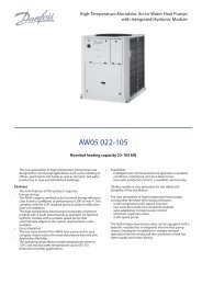
Part load performancesWith the rapid increase in energy costs and the care aboutenvironmental impacts of electricity production, the powerconsumption of air conditioning equipment has become animportant topic. The energy efficiency of a unit at full load israrely representative of the actual performance of the units, ason average a unit works less than 5% of the time at full load.The heat load of a building depends on many factors, such asthe outside air temperature, the exposure to the sun and itsoccupation.Consequently it is preferable to use the seasonal energyefficiency, calculated at several operating points that arerepresentative for the unit utilisation.Sound spectrumESEER (EUROVENT)The ESEER (European seasonal energy efficiency ratio) permitsevaluation of the average energy efficiency at part load, based onfour operating conditions defined by Eurovent. The ESEER isthe average value of energy efficiency ratios (EER) at differentoperating conditions, weighted by the operating time.ESEER (European seasonal energy efficiency ratio)Load%Air temperature°CEnergy efficiency Operatingfime, %100 35 EER 1375 30 EER 23350 25 EER 34125 20 EER 423ESEER = EER 1x 3% + EER 2x 33% + EER 3x 41% + EER 4x 23%Note: Constant leaving water temperature = 7°C<strong>BW10</strong> - standard unitOctave bands, HzSound power125 250 500 1k 2k 4k level020 dB(A) 60.1 52.8 51.6 63.2 60.8 56.5 dB(A) 67.0025 dB(A) 63.9 56.3 55.7 63.2 59.8 58.2 dB(A) 68.5030 dB(A) 61.1 58.8 57.6 64.0 62.6 59.9 dB(A) 69.0035 dB(A) 64.1 59.2 59.0 63.9 61.2 57.8 dB(A) 69.3040 dB(A) 58.6 59.7 58.4 66.7 63.6 58.5 dB(A) 70.0045 dB(A) 56.9 56.1 56.8 66.2 64.8 62.1 dB(A) 70.1050 dB(A) 47.2 59.6 64.6 67.9 65.7 56.3 dB(A) 71.5060 dB(A) 43.2 60.9 65.2 67.5 67.2 56.7 dB(A) 72.0070 dB(A) 46.3 61.4 66.8 67.4 65.9 54.8 dB(A) 72.0080 dB(A) 40.1 61.2 65.4 69.6 67.6 54.8 dB(A) 73.0090 dB(A) 50.6 64.1 63.9 69.2 68.9 58.4 dB(A) 73.4<strong>BW10</strong> - Unit with low-noise option (option 257)Octave bands, HzSound power125 250 500 1k 2k 4k level020 dB(A) 58.7 57.9 49.8 60.3 57.2 51.2 dB(A) 65.0025 dB(A) 58.2 57.4 55.2 61.6 57.5 54.2 dB(A) 65.8030 dB(A) 58.2 57.4 55.5 60.8 58.7 54.3 dB(A) 65.8035 dB(A) 58.2 57.4 58.5 62.2 58.8 53.8 dB(A) 66.6040 dB(A) 63.9 58.2 56.4 63.6 59.8 53.0 dB(A) 68.4045 dB(A) 58.2 57.4 56.3 64.6 62.5 58.0 dB(A) 68.4050 dB(A) 47.5 57.4 61.0 65.4 61.8 50.7 dB(A) 68.4060 dB(A) 43.2 58.5 61.3 64.7 63.1 50.9 dB(A) 68.6070 dB(A) 46.6 59.4 63.3 65.0 62.2 49.3 dB(A) 69.0080 dB(A) 39.4 58.1 60.9 66.1 62.8 48.2 dB(A) 69.0090 dB(A) 50.4 61.5 59.8 66.2 64.6 52.3 dB(A) 69.9Electrical data notes and operating conditions:• <strong>BW10</strong> units have a single power connection point, located immediately upstreamof the main disconnect switch.• The control box includes the following standard features:- a main disconnect switch,- the starter and motor protection devices for each compressor and the pumps- the control devices• Field connections:• All connections to the system and the electrical installations must be in fullaccordance with all applicable local codes.• The <strong>BW10</strong> units are designed and built to ensure conformance with these codes.The recommendations of European standard EN 60204-1 (machine safety ‐electrical machine components ‐ part 1: general regulations - corresponds to IEC60204-1) are specifically taken into account, when designing the electrical unitequipment.Notes:• Generally the recommendations of IEC 60364 are accepted as compliance with therequirements of the installation directives. Conformance with EN 60204-1 is thebest means of ensuring compliance with the Machines Directive § 1.5.1.• Annex B of EN 60204-1 describes the electrical characteristics used for theoperation of the machines.1. The operating conditions for the units are specified below:Environment* ‐ Environment as classified in IEC 60364 § 3:- ambient temperature range: +5°C to +40°C, class AA4- humidity range (non-condensing)*:- 50% relative humidity at 40°C- 90% relative humidity at 20°C- altitude: ≤ 2000 m (see note for table 4.5 in the IOM)- indoor installation*- presence of water: class AD2 (possibility of water droplets)- presence of hard solids, class 4S2 (no significant dust present)- presence of corrosive and polluting substances, class 4C2 (negligible)- vibration and shock, class AG2, AH2- competence of personnel, class BA4* (trained personnel ‐ IEC 60364)2. Power supply frequency variation: ± 2 Hz.3. The neutral (N) conductor must not be connected directly to the unit (if necessaryuse a transformer).4. Over-current protection of the power supply conductors is not provided with theunit.5. The factory-installed disconnect switch(es)/circuit breaker(s) is (are) of a typesuitable for power interruption in accordance with EN 60947.6. The units are designed for simplified connection on TN(s) networks (IEC 60364).For IT networks provide a local earth and consult competent local organisations tocomplete the electrical installation.7. Derived currents: If protection by monitoring of derived currents is necessary toensure the safety of the installation, the control of the cut-out value must take thepresence of leak currents into consideration that result from the use of frequencyconverters in the unit. A value of at least 150 mA is recommended to controldifferential protection devices.NOTE: If particular aspects of an actual installation do not conform to theconditions described above, or if there are other conditions which should beconsidered, always contact your local Danfoss representative.* The protection level of the control boxes required to conform to this class is IPX1B(according to reference document IEC 60529). All <strong>BW10</strong> units fulfil this protectioncondition.Units equipped with front casing panel meet class IP23. If the casing panel hasbeen removed, access to energised components is protected to level IPXXB.10
Operating limits<strong>BW10</strong> Minimum MaximumEvaporatorEntering water temperature at start-up °C 7.5* 27Leaving water temperature during operation °C 5** 20Entering/leaving water temperature difference K 2.5 7CondenserEntering water temperature at start-up °C 15*** 60****Leaving water temperature during operation °C 20 65Entering/leaving water temperature difference K 2.5 18* For entering water temperatures below 7.5°C at start-up, contact Danfoss.** If the leaving water temperature is below 5°C, a frost protection solution must be used. Pleaserefer to option 6 for evaporator leaving water low-temperature applications (< 5°C).*** For applications with a condenser entering air temperature below 15°C the use of a three-wayvalve is recommended. This three-way valve can be controlled by the 0-10 V analogue output ofthe control system.**** For a water flow rate that corresponds to a maximum water-side temperature difference of 5 K.Condenser leaving water temperature, °C<strong>BW10</strong> + option 272 (geothermal application) Minimum MaximumEvaporatorEntering water temperature at start-up °C -2.5* 25Leaving water temperature during operation °C -5* 20Entering/leaving water temperature difference K 2.5 5CondenserEntering water temperature at start-up °C 15** 60***Leaving water temperature during operation °C 20 65Entering/leaving water temperature difference K 2.5 18* A frost protection solution must be used.** For applications with a condenser entering air temperature below 15°C the use of a three-wayvalve is recommended. This three-way valve can be controlled by the 0-10 V analogue output ofthe control system.*** For a water flow rate that corresponds to a maximum water-side temperature difference of 5 K.Operating range6560555045403530252015Option 272Standard-8 -6 -4 -2 0 2 4 6 8 10 12 14 16 18 20Evaporator leaving water temperature, °CWater loop volumeEvaporator and condenser• Minimum volumeA minimum water volume is required for correct unitoperation. The minimum water loop volume can be calculatedin accordance with the following formula:Volume = CAP(kW) x N* = litres, where CAP is the coolingcapacity at nominal operating conditions.Air conditioning application N*<strong>BW10</strong> 020-090 3.5The water volume in the condenser loop has no impact on theoperation of the unit.Note: In the heat pump mode (unit control based on thehot-water temperature) the minimum volume of the condenserloop must be cal culated the same way as for the evaporator loop,replacing the cooling capacity with the heating capacity.• Industrial process coolingCertain industrial process applications may require highstability of the leaving water temperature levels. In this casethe values above must be increased.• Maximum volumeUnits with hydronic module incorporate an expansion tanksized for the maximum water loop volume.The table below gives the maximum water loop volume (inlitres) for pure water or ethylene glycol with variousconcentrations.<strong>BW10</strong> 020-045 060-090Static pressure kPa 100 200 300 100 200 300bar 1 2 3 1 2 3Pure water l 220 450 75 340 225 11510% ethylene glycol l 165 110 53 255 170 8520% ethylene glycol l 100 70 35 150 100 5035% ethylene glycol l 85 55 30 130 85 45<strong>BW10</strong> standard unit<strong>BW10</strong> unit with option 272 (brine to water)Option 272: Condenser-side high-temperature water production, with glycol solution on theevaporator side11