AW05 022-105 - Heat Pumps
AW05 022-105 - Heat Pumps
AW05 022-105 - Heat Pumps

Create successful ePaper yourself
Turn your PDF publications into a flip-book with our unique Google optimized e-Paper software.
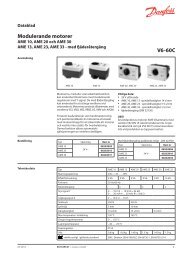
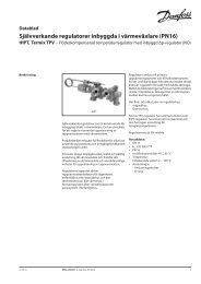
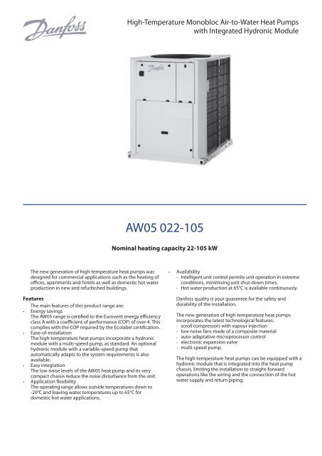
High-Temperature Monobloc Air-to-Water <strong>Heat</strong> <strong>Pumps</strong>with Integrated Hydronic Module<strong>AW05</strong> <strong>022</strong>-<strong>105</strong>Nominal heating capacity 22-<strong>105</strong> kWThe new generation of high-temperature heat pumps wasdesigned for commercial applications such as the heating ofoffices, apartments and hotels as well as domestic hot waterproduction in new and refurbished buildings.FeaturesThe main features of this product range are:••Energy savingsThe <strong>AW05</strong> range is certified to the Eurovent energy efficiencyclass A with a coefficient of performance (COP) of over 4. Thiscomplies with the COP required by the Ecolabel certification.••Ease-of-installationThe high-temperature heat pumps incorporate a hydronicmodule with a multi-speed pump, as standard. An optionalhydronic module with a variable-speed pump thatautomatically adapts to the system requirements is alsoavailable.••Easy integrationThe low noise levels of the <strong>AW05</strong> heat pump and its verycompact chassis reduce the noise disturbance from the unit.••Application flexibilityThe operating range allows outside temperatures down to-20°C and leaving water temperatures up to 65°C fordomestic hot water applications.••Availability--Intelligent unit control permits unit operation in extremeconditions, minimising unit shut-down times.--Hot water production at 65°C is available continuously.Danfoss quality is your guarantee for the safety anddurability of the installation.The new generation of high-temperature heat pumpsincorporates the latest technological features:--scroll compressors with vapour injection--low-noise fans made of a composite material--auto-adaptative microprocessor control--electronic expansion valve--multi-speed pump.The high-temperature heat pumps can be equipped with ahydronic module that is integrated into the heat pumpchassis, limiting the installation to straight-forwardoperations like the wiring and the connection of the hotwater supply and return piping.
Quiet operation••Compressors--Low-noise scroll compressors with low vibration level.--The compressor assembly is installed on an independentchassis and supported by anti-vibration mountings.--Dynamic suction and discharge piping supports,minimising vibration transmission.••Evaporator section--Vertical evaporator coils--Protection grilles on anti-vibration mountings to protectthe heat exchanger against possible shocks.--Latest-generation low-noise Flying Bird fans, made of acomposite material, are now even quieter and do notgenerate intrusive low-frequency noise.--Rigid fan installation for reduced start-up noise.Easy and fast installation••Integrated hydronic module (option)--Multi-speed centrifugal water pump, based on the pressureloss of the hydronic installation.--Water filter protects the water pump against circulatingdebris.--Pump protected against cavitation by a pressuretransducer that measures the entering water pressure.--Overpressure valve, set to 4 bar.--Thermal insulation and frost protection down to -20°C,using an electric resistance heater (see table of options).••Physical features--The unit has a small footprint and a low height (1329 mm)allowing it to blend in with any architectural styles.--The unit is enclosed by easily removable panels, covering allcomponents (except condensers and fans).••Simplified electrical connections--Single power supply point without neutral.--Main disconnect switch with high trip capacity.--Transformer for safe 24 V control circuit supply included.••Fast commissioning--Systematic factory operation test before shipment.--Quick-test function for step-by-step verification of theinstruments, electrical components and motors.Economical operation••Increased energy efficiency--The exceptional energy efficiency level (COP) of thehigh-temperature heat pumps in the heating mode is theresult of a long qualification and optimisation process.--The electronic expansion device (EXV) allows operation at alower condensing pressure (COP optimisation).--Dynamic superheat management for better utilisation ofthe condenser surface.••Reduced maintenance costs--Maintenance-free scroll compressors with vapourinjection.--The control system offers fast diagnosis of possibleincidents and their history.Environmental care••Ozone-friendly R-407C refrigerant--Chlorine-free refrigerant of the HFC group with zero ozonedepletion potential.--Very efficient - ensures an increased energy efficiency ratio(COP).••Leak-tight refrigerant circuit--Brazed refrigerant connections for increased leaktightness.--Reduction of leaks due to elimination of capillary tubes(TXVs).--Verification of pressure transducers and temperaturesensors without transferring refrigerant charge.Superior reliability••State-of-the-art concept--Cooperation with specialist laboratories and use of limitsimulation tools (finite element calculations) for the designof the critical components, e.g. motor supports, suction/discharge piping etc.••Auto-adaptive control--Control algorithm prevents excessive compressor cyclingand permits reduction of the water quantity in thehydronic circuit.••Exceptional endurance tests--Corrosion resistance tests in salt mist in the laboratory.--Accelerated ageing test on components that aresubmitted to continuous operation: compressor piping,fan supports.--Transport simulation test in the laboratory on a vibratingtable.2 VDGFG102
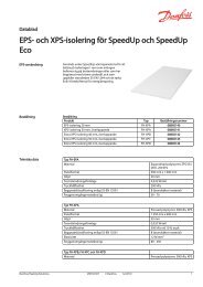
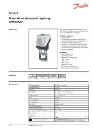
Control systemThe control system combines intelligence with operatingsimplicity. The control constantly monitors all machineparameters and precisely manages the operation ofcompressors, expansion devices, fans and of the condenserwater pump for optimum energy efficiency.••Energy management--Seven-day internal time schedule clock: permits unit on/off control and operation at a second set point.--Set point reset based on the outside air temperature or thereturn water temperature or on the water heat exchangerdelta T.--Master/slave control of two heat pumps operating inparallel with operating time equalisation and automaticchange-over in case of a unit fault (option).--Start/stop based on the outside air temperature.••Ease-of-use--The new backlighted LCD interface includes a manualcontrol potentiometer to ensure legibility under anylighting conditions.--The information is displayed clearly in English, French,German, Italian and Spanish (for other languages pleaseconsult Danfoss.--The navigation uses intuitive tree-structure menus, similarto the Internet browers. They are user-friendly and permitquick access to the principal operat-ing parameters:number of compressors operating, suction/dischargepressure, compressor operating hours, set point, airtemperature, entering/leaving water temperature.--As standard the unit includes a board for the control of aboiler and four electric resistance heater stages.Operator interfaceRemote operating mode with volt-free contacts(standard)A simple two-wire communication bus between the RS485port of the high-temperature heat pumps and the CCN offersmultiple remote control, monitoring and diagnosticpossibilities.Danfoss offers a vast choice of control products, speciallydesigned to control, manage and supervise the operation of aheating system. Please consult your Danfoss representative formore information on these products.--Start/stop: opening of this contact will shut down the heatpump.--Dual set point: closing of this contact activates a secondheating set point (example: unoccupied mode).--Demand limit: closing of this contact limits the maximumheat pump capacity to a predefined value.--User safety: this contact is connected in series with thewater flow switch and can be used for any customer safetyloop.--Water pump control.--Alert indication: this volt-free contact indicates thepresence of a minor fault.--Alarm indication: this volt-free contact indicates thepresence of a major fault that has led to the shut-down ofthe refrigerant circuit.Remote interface (accessory)This accessory includes a box that can be mounted inside thebuilding. The power supply is provided via a 220 V/24 Vtransformer supplied. This interface allows access to thesame menus as the unit interface and can be installed up to300 m from the <strong>AW05</strong> unit.Flying Bird IV fanCircuit B Total CapacityVDGFG1023
Options and accessoriesOptions No. Description Advantages UseAnti-corrosion protection, 3A Fins made of pre-treated aluminiumImproved corrosion resistance, recommended for marine <strong>AW05</strong> <strong>022</strong>-<strong>105</strong>traditional coils(polyurethane or epoxy)environmentsUnit with discharge air ducts 11 Fans with available pressure - max. 100 Pa Enhances unit adjustment during installation (e.g. under a <strong>AW05</strong> <strong>022</strong>-<strong>105</strong>roof)Low noise level 15 Acoustic compressor enclosure Noise emission reduction <strong>AW05</strong> <strong>022</strong>-<strong>105</strong>Very low noise level 15LS Acoustic compressor enclosure and fan speed Noise emission reduction <strong>AW05</strong> <strong>022</strong>-<strong>105</strong>reduction, when ambient air temperature isabove 20°C.Soft starter 25 Electronic compressor starter Reduced compressor start-up current <strong>AW05</strong> <strong>022</strong>-<strong>105</strong>Frost protection down to -20°C 42 Electric heater on the hydronic module (option116)Hydronic module frost protection at low outside temperature <strong>AW05</strong> <strong>022</strong>-<strong>105</strong>with option 116FLow-pressure single-pump 116F See hydronic module chapter Easy and fast installation <strong>AW05</strong> <strong>022</strong>-<strong>105</strong>hydronic moduleJBus gateway 148B Two-directional communications board, Easy connection by communication bus to a building<strong>AW05</strong> <strong>022</strong>-<strong>105</strong>complies with JBus protocolmanagement systemBacNet gateway 148C Two-directional communications board, Easy connection by communication bus to a building<strong>AW05</strong> <strong>022</strong>-<strong>105</strong>complies with BacNet protocolmanagement systemLonTalk gateway 148D Two-directional communications board, Easy connection by communication bus to a building<strong>AW05</strong> <strong>022</strong>-<strong>105</strong>complies with LonTalk protocolmanagement system<strong>Heat</strong>ing system control* 157 Additional remotely installed control box, Allows control of pre-configured heating systems <strong>AW05</strong> <strong>022</strong>-<strong>105</strong>allows control of the various heating systemcomponentsWater screw connection265 Victaulic screw connection at the condenser Permits customer connections to be screwed to the unit <strong>AW05</strong> 035-055between the customer’scondenser and the unit(standard on sizes <strong>022</strong>-030)Welded water connection 267 Welded Victaulic connection Permits customer connections to be welded to the unit <strong>AW05</strong> 035-055between the customer’scondenser and the unitAccessories Description Advantages UseRemote user interfaceRemotely installed user interface (viaRemote heat pump control up to 300 m <strong>AW05</strong> <strong>022</strong>-<strong>105</strong>communication bus).JBus gateway communicationTwo-directional communications board, Connection by communication bus to a building<strong>AW05</strong> <strong>022</strong>-<strong>105</strong>complies with JBus protocolmanagement systemBacNet gateway communicationTwo-directional communications board, Connection by communication bus to a building<strong>AW05</strong> <strong>022</strong>-<strong>105</strong>complies with BacNet protocolmanagement systemLonTalk gateway communicationTwo-directional communications board,complies with LonTalk protocolConnection by communication bus to a buildingmanagement system<strong>AW05</strong> <strong>022</strong>-<strong>105</strong>Twinning (lead-lag kit)* Option available in 2011.Unit equipped with an additional field-installedleaving water temperature sensor, allowingmaster/slave operation of two units connectedin parallelOperation of two units connected in parallel with operatingtime equalisation<strong>AW05</strong> <strong>022</strong>-<strong>105</strong>Electrical data and operating conditions notes:• <strong>AW05</strong> <strong>022</strong>-<strong>105</strong> units have a single power connection point located immediatelyupstream of the main disconnect switch.• The control box includes the following standard features:- a main disconnect switch,- starter and motor protection devices for the compressor, the fan and thepump,- the control devices.• Field connections:All connections to the system and the electrical installations must be in fullaccordance with all applicable local codes.• The W05 units are designed and built to ensure conformance with these codes.The recommendations of European standard EN 60204‐1 (machine safety ‐electrical machine components ‐ part 1: general regulations - corresponds toIEC 60204-1) are specifically taken into account, when designing the electricalequipment.Notes:• Generally the recommendations of IEC 60364 are accepted as compliance withthe requirements of the installation directives. Conformance with EN 60204-1 isthe best means of ensuring compliance with the Machinery Directive § 1.5.1.• Annex B of EN 60204‐1 describes the electrical characteristics used for theoperation of the machines.• The operating environment for the <strong>AW05</strong> units is specified below:1. Environment* ‐ Environment as classified in EN 60721 (corresponds toIEC 60721):‐ outdoor installation*‐ ambient temperature range: ‐20°C to +40°C, class 4K4H‐ altitude: ≤ 2000 m‐ presence of hard solids, class 4S2 (no significant dust present)‐ presence of corrosive and polluting substances, class 4C2 (negligible)2. Power supply frequency variation: ± 2 Hz.3. The neutral (N) conductor must not be connected directly to the unit (ifnecessary use a transformer).4. Overcurrent protection of the power supply conductors is not provided with theunit.5. The factory-installed disconnect switch is of a type suitable for powerinterruption in accordance with EN 60947-3 (corresponds to IEC 60947-3)6. The units are designed for connection to TN networks (IEC 60364). For ITnetworks the earth connection must not be at the network earth. Provide alocal earth, consult competent local organisations to complete the electricalinstallation.Caution: If particular aspects of an actual installation do not conform to theconditions described above, or if there are other conditions which shouldbe considered, always contact your local Danfoss representative.* The required protection level for this class is IP43BW (according to referencedocument IEC 60529). All <strong>AW05</strong> units are protected to IP44CW and fulfil thisprotection condition.4 VDGFG102
Physical data, <strong>AW05</strong><strong>AW05</strong> <strong>022</strong> 030 035 045 055 075 <strong>105</strong>Nominal heating capacity* kW 20.8 25.7 32.2 43.6 52.2 66.7 102Power input kW 5.8 7.3 9.2 11.8 14 19.4 28.1Coefficient of performance (COP) kW/kW 3.6 3.5 3.5 3.7 3.7 3.4 3.6Eurovent class, heating A A A A A A ANominal heating capacity** kW 21.2 26.1 32.8 43.8 52.8 64.7 102Power input kW 4.9 6.1 7.8 9.9 11.9 16.1 23.6Coefficient of performance (COP) kW/kW 4.3 4.3 4.2 4.4 4.4 4.0 4.3Eurovent class, heating A A A A A B AOperating weight***Standard unit (without hydronic kit) kg 343 396 421 509 533 900 1020Standard unit (plus hydronic module option) kg 349 403 436 524 549 926 1046Sound levelsSound power level 10 -12 W**** dB(A) 81 82 83 83 84 84 85Sound pressure level at 10 m† dB(A) 50 51 51 51 53 52 53CompressorHermetic scroll 48.3 r/sQuantity 1 1 1 1 1 2 2Number of capacity stages 1 1 1 1 1 2 2RefrigerantR-407CCharge kg 8.0 8.8 9.7 10.0 13.2 22.0 26.5Capacity controlMinimum capacity % 100 100 100 100 100 50 50CondenserDirect-expansion plate heat exchangerWater volume l 4.9 6.4 8.2 9.6 12.1 16.4 22.7Max. water-side operating pressure without hydronic module kPa 1000 1000 1000 1000 1000 1000 1000Max. water-side operating pressure with hydronic module kPa 400 400 400 400 400 400 400FanAxial with rotating shroud, Flying Bird IVQuantity 1 1 1 1 1 2 2Total air flow (high speed) l/s 3800 3800 3800 3800 3800 7600 7600Speed, standard unit r/s 12 12 12 12 12 12 12Speed, unit with option 11 r/s 16 16 16 16 16 16 16EvaporatorGrooved copper tubes and aluminium finsHydronic module (option 116)Three-speed single pumpPump, Victaulic screen filter, safety valve, purge valves (water and air), cavitation presssure sensorWater connections with/without hydronic moduleVictaulicConnections†† inch 1-1/4 1-1/4 1-1/2 1-1/2 1-1/2 2 2Outside diameter mm 42.4 42.4 48.3 48.3 48.3 60.3 60.3Chassis paint colour Colour code: RAL 7035* Standardised Eurovent conditions: entering leaving condenser water temperature = 40°C/45°C, outside air temperature db/wb = 7°C/6°C** Standardised Eurovent conditions: entering leaving condenser water temperature = 30°C/35°C, outside air temperature db/wb = 7°C/6°C*** Weight shown is a guideline only. To find out the unit refrigerant charge, please refer to the unit nameplate..**** In accordance with ISO 9614-1 and certified by Eurovent. The values have been rounded and are for information only and not contractually binding† For information, calculated from the sound power level Lw(A)†† Units <strong>AW05</strong> <strong>022</strong> and <strong>AW05</strong> 030 include two sleeves for a 1-1/4” Victaulic to 1-1/4” screw connection as standard.Electrical data, <strong>AW05</strong><strong>AW05</strong> - standard unit (without hydronic module) <strong>022</strong> 030 035 045 055 075 <strong>105</strong>Power circuitNominal power supply V-ph-Hz 400-3-50Voltage range V 360-440Control circuit supply24 V, via internal transformerMaximum start-up current (Un)*Standard unit A 104.6 102.6 131.0 171.0 191.0 154.5 221.5Unit with electronic starter option A 56.1 55.1 70.0 90.8 101.2 101.5 142.5Unit power factor at maximum capacity** 0.82 0.82 0.82 0.82 0.82 0.82 0.82Maximum unit power input** kW 8.7 11.6 12.9 14.6 16.8 25.8 33.7Nominal unit current draw*** A 14.3 16.9 20.2 23.2 27.9 39.7 55.1Maximum unit current draw (Un)**** A 16.1 21.3 24.1 27.1 31.1 47.5 61.5Maximum unit current draw (Un-10%)† A 21.1 28.4 32.2 36.4 42.0 63.7 83.3Customer-side unit power reserveCustomer reserve at the 24 V control power circuitShort-circuit stability and protectionSee table on the next page* Maximum instantaneous start-up current (maximum operating current of the compressor + fan current + locked rotor current of the compressor).** Power input, compressor and fan, at the unit operating limits (saturated suction temperature 10°C, saturated condensing temperature 65°C) and nominal voltage of 400 V (data given on the unit nameplate).*** Standardised Eurovent conditions: condenser entering/leaving water temperature = 40°C/45°C, outside air temperature db/wb = 7°C/6°C.**** Maximum unit operating current at maximum unit power input and 400 V (values given on the unit nameplate).† Maximum unit operating current at maximum unit power input and 360 V.VDGFG1025
Dimensions/clearances, <strong>AW05</strong><strong>AW05</strong> <strong>022</strong>-035 units with and without hydronic module111013271000100030013301000<strong>AW05</strong> 045-055 units with and without hydronic module1000LegendAll dimensions are in mmRequired clearances for air flowRecommended space for maintenanceWater inletWater outletAir outlet, do not obstructControl boxPower cable connection111421001330NOTES:A Non-certified drawings.Refer to the certified dimensional drawingssupplied with the unit or available on request,when designing an installation. For the location offixing points, weight distribution and coordinatesof the centre of gravity refer to the certifieddimensional drawings.B In multiple-unit installations (maximum four units),the side clearance between the units should beincreased from 1000 to 2000 mm.C The height of the solid surface must not exceed 2m.1000100010003001000VDGFG1027
Dimensions/clearances <strong>AW05</strong> (continued)<strong>AW05</strong> 075-<strong>105</strong> units with and without hydronic module210<strong>022</strong>73LegendAll dimensions are in mm133010002053100<strong>022</strong>61300Required clearances for air flowRecommended space for maintenanceWater inletWater outletAir outlet, do not obstructControl boxPower cable connection211NOTES:A Non-certified drawings.Refer to the certified dimensional drawingssupplied with the unit or available on request,when designing an installation. For the location offixing points, weight distribution and coordinatesof the centre of gravity refer to the certifieddimensional drawings.B In multiple-unit installations (maximum four units),the side clearance between the units should beincreased from 1000 to 2000 mm.C The height of the solid surface must not exceed 2m.1000110008 VDGFG102
<strong>Heat</strong>ing capacities, <strong>AW05</strong>Outside air temperature, °C-20 -15 -10 -5 0 2 5<strong>AW05</strong> EWT Cap Unit Flow Dp Cap Unit Flow Dp Cap Unit Flow Dp Cap Unit Flow Dp Cap Unit Flow Dp Cap Unit Flow Dp Cap Unit Flow Dp°C kW kW l/s kPa kW kW l/s kPa kW kW l/s kPa kW kW l/s kPa kW kW l/s kPa kW kW l/s kPa kW kW l/s kPa<strong>022</strong> 25 10.2 4.80 0.49 1 12.1 4.80 0.58 2 13.9 4.80 0.67 2 15.9 4.80 0.76 3 18.0 4.60 0.87 4 19.0 4.60 0.91 4 20.4 4.60 0.98 5030 10.1 5.70 0.58 1 13.1 5.70 0.58 1 16.0 5.70 0.77 2 19.0 5.80 0.91 3 21.9 5.60 1.05 3 23.2 5.60 1.11 4 25.2 5.70 1.21 4035 15.6 6.60 0.75 1 18.1 6.80 0.87 2 21.0 6.90 1.01 3 24.3 7.00 1.16 3 27.7 6.90 1.33 4 29.2 7.00 1.40 5 31.6 7.00 1.52 5045 20.0 8.50 0.96 1 24.4 8.70 1.17 3 28.5 9.00 1.37 3 33.1 9.20 1.59 5 38.1 9.10 1.83 6 40.1 9.10 1.93 6 41.3 9.00 1.98 7055 25.6 9.40 1.23 2 29.9 10.0 1.43 3 34.5 10.4 1.66 4 39.8 10.7 1.91 5 45.3 10.8 2.17 6 47.5 10.8 2.28 6 50.3 10.9 2.42 7075 32.0 14.0 1.54 2 37.6 14.4 1.80 3 43.8 14.7 2.10 4 50.7 14.9 2.44 5 58.3 14.7 2.80 7 61.6 14.8 2.96 7 63.1 14.8 3.03 8<strong>105</strong> 47.6 19.3 2.29 4 54.9 19.9 2.64 5 64.0 20.4 3.08 6 74.1 20.9 3.56 8 85.4 21.2 4.10 11 90.2 21.2 4.33 12 97.6 21.7 4.69 14<strong>022</strong> 30 9.8 5.20 0.47 1 11.8 5.20 0.57 2 13.9 5.20 0.67 2 15.8 5.20 0.76 3 17.9 4.90 0.86 3 18.8 4.90 0.90 4 20.2 4.90 0.97 4030 10.2 5.90 0.49 1 13.1 6.00 0.62 1 15.9 6.00 0.76 2 18.8 6.10 0.91 3 21.7 6.00 1.04 3 22.9 6.10 1.10 4 24.8 6.10 1.19 4035 15.7 7.10 0.76 1 18.2 7.30 0.87 2 20.9 7.50 1.01 2 24.1 7.60 1.16 3 27.5 7.60 1.32 4 29.0 7.60 1.39 4 31.2 7.70 1.50 5045 18.7 9.10 0.89 1 23.4 9.30 1.12 3 28.2 9.60 1.36 3 32.7 9.80 1.57 4 37.6 9.80 1.81 6 39.6 9.80 1.90 6 41.8 9.80 2.01 7055 25.6 10.0 1.23 2 29.8 10.6 1.43 3 34.4 11.1 1.65 4 39.5 11.5 1.90 5 45.0 11.7 2.16 6 47.2 11.7 2.27 6 50.4 11.8 2.43 7075 31.8 14.9 1.53 2 37.3 15.4 1.79 3 43.4 15.8 2.09 4 50.3 16.1 2.42 5 57.8 16.0 2.78 6 61.0 16.0 2.93 7 63.8 16.1 3.07 8<strong>105</strong> 47.8 20.6 2.30 3 55.1 21.4 2.65 5 63.9 22.0 3.07 6 73.9 22.6 3.55 8 84.9 22.9 4.09 10 89.7 23.0 4.31 12 97.2 23.4 4.67 13<strong>022</strong> 35 10.0 5.50 0.48 1 11.9 5.50 0.57 2 13.9 5.50 0.67 2 15.7 5.60 0.76 3 17.8 5.30 0.86 3 18.6 5.30 0.90 4 20.0 5.30 0.96 4030 10.4 6.20 0.50 1 13.2 6.30 0.63 1 15.9 6.40 0.76 2 18.7 6.60 0.90 2 21.5 6.50 1.03 3 22.7 6.50 1.09 4 24.6 6.60 1.18 4035 15.9 7.70 0.77 1 18.3 7.90 0.88 2 21.0 8.10 1.01 2 24.0 8.30 1.16 3 27.4 8.20 1.32 4 28.8 8.30 1.39 4 30.9 8.40 1.49 5045 18.7 9.60 0.89 1 23.3 9.90 1.11 3 28.0 10.2 1.35 3 32.3 10.5 1.56 4 37.2 10.6 1.79 5 39.1 10.6 1.88 6 42.1 10.7 2.03 7055 25.7 10.6 1.24 2 29.8 11.3 1.44 3 34.3 11.9 1.65 3 39.3 12.3 1.89 4 44.7 12.6 2.16 6 46.9 12.6 2.26 6 50.2 12.8 2.42 7075 31.7 15.9 1.53 2 37.1 16.4 1.79 3 43.2 16.9 2.08 4 49.9 17.4 2.41 5 57.3 17.3 2.76 6 60.5 17.5 2.91 7 64.7 17.6 3.12 8<strong>105</strong> 48.1 22.0 2.32 3 55.4 23.0 2.67 5 64.0 23.8 3.08 6 73.8 24.5 3.56 8 84.7 24.9 4.08 10 89.4 25.0 4.31 11 96.8 25.4 4.66 13<strong>022</strong> 40 10.1 5.90 0.48 1 12.0 5.90 0.58 2 14.0 6.00 0.67 2 15.8 6.00 0.76 3 17.7 5.80 0.86 3 18.6 5.80 0.90 4 19.9 5.80 0.96 4030 9.5 6.60 0.45 1 12.5 6.70 0.60 1 15.4 6.90 0.74 2 18.4 7.20 0.88 2 21.4 7.10 1.03 3 22.5 7.10 1.09 3 24.4 7.20 1.18 4035 16.1 8.30 0.78 1 18.5 8.60 0.89 2 21.1 8.80 1.02 2 24.0 9.00 1.16 3 27.3 9.00 1.32 4 28.6 9.00 1.38 4 30.7 9.10 1.48 5045 19.1 10.3 0.91 1 23.5 10.6 1.12 3 27.9 11.0 1.35 3 32.1 11.3 1.55 4 36.7 11.5 1.77 5 38.7 11.5 1.87 6 41.7 11.7 2.01 6055 25.9 11.5 1.25 2 30.0 12.2 1.45 3 34.4 12.8 1.66 3 39.2 13.3 1.89 4 44.6 13.6 2.15 5 46.7 13.6 2.25 6 50.0 13.9 2.41 7075 31.7 17.0 1.53 2 37.1 17.6 1.79 3 43.0 18.2 2.08 4 49.7 18.8 2.40 5 57.0 18.8 2.75 6 60.1 19.0 2.90 7 65.0 19.3 3.13 8<strong>105</strong> 48.5 23.5 2.34 3 55.9 24.7 2.70 5 64.4 25.8 3.11 6 74.0 26.7 3.57 8 84.8 27.1 4.09 10 89.4 27.3 4.31 11 96.6 27.8 4.66 13<strong>022</strong> 45 10.4 6.30 0.50 1 12.2 6.40 0.58 2 14.1 6.50 0.68 2 15.9 6.50 0.77 3 17.8 6.40 0.86 3 18.6 6.40 0.90 4 19.9 6.40 0.96 4030 9.3 7.10 0.44 1 12.3 7.30 0.59 1 15.3 7.40 0.73 2 18.3 7.80 0.88 2 21.4 7.70 1.03 3 22.5 7.80 1.09 3 24.3 7.90 1.17 4035 15.9 9.00 0.76 1 18.7 9.30 0.90 2 21.2 9.50 1.03 2 24.1 9.70 1.16 3 27.2 9.70 1.32 4 28.6 9.80 1.38 4 30.6 10.0 1.48 5045 17.0 11.1 0.81 1 21.8 11.5 1.04 3 28.0 11.9 1.35 3 32.0 12.3 1.55 4 36.5 12.4 1.76 5 38.4 12.6 1.86 5 41.3 12.7 2.00 6055 25.8 12.7 1.23 2 30.4 13.3 1.47 3 34.7 13.9 1.67 3 39.3 14.3 1.90 4 44.5 14.7 2.15 5 46.7 14.8 2.26 6 49.8 15.0 2.41 6075 31.8 18.1 1.54 2 37.1 18.9 1.79 3 43.1 19.7 2.08 4 49.6 20.3 2.40 5 56.8 20.5 2.75 6 59.9 20.7 2.89 7 64.7 21.1 3.13 8<strong>105</strong> 49.0 25.0 2.37 3 56.6 26.6 2.73 5 64.9 27.9 3.14 6 74.5 29.0 3.60 8 85.0 29.7 4.11 10 89.6 29.9 4.33 11 96.8 30.4 4.67 13<strong>022</strong> 50 10.7 6.80 0.51 1 12.5 6.90 0.60 2 14.3 7.00 0.69 2 16.1 7.10 0.78 3 18.0 7.00 0.87 3 18.7 7.00 0.91 4 19.9 7.00 0.97 4030 10.5 7.60 0.50 1 13.2 7.90 0.63 1 16.0 8.10 0.76 2 18.8 8.50 0.90 2 21.5 8.50 1.04 3 22.6 8.60 1.09 3 24.3 8.70 1.18 4035 16.3 9.70 0.78 1 18.9 10.0 0.92 2 21.4 10.3 1.04 2 24.2 10.5 1.17 3 27.2 10.6 1.32 4 28.6 10.7 1.38 4 30.5 10.9 1.48 4045 18.9 12.1 0.90 1 23.3 12.5 1.11 3 27.7 12.8 1.32 3 32.1 13.3 1.55 4 36.4 13.6 1.76 5 38.2 13.7 1.85 5 41.1 13.9 1.99 6055 26.6 14.1 1.27 2 31.0 14.6 1.50 3 35.1 15.2 1.70 3 39.6 15.6 1.92 4 44.6 16.0 2.16 5 46.7 16.1 2.26 6 49.8 16.4 2.41 6075 32.0 19.4 1.55 2 37.3 20.4 1.81 3 43.2 21.2 2.09 4 49.7 22.0 2.41 5 56.8 22.3 2.75 6 59.8 22.6 2.90 6 64.6 23.0 3.13 7<strong>105</strong> 49.7 26.7 2.41 3 57.5 28.7 2.78 5 65.7 30.3 3.18 6 75.3 31.7 3.65 8 85.7 32.6 4.15 10 90.1 32.9 4.36 11 97.2 33.5 4.71 12<strong>022</strong> 55 - - - - - - - - 14.9 8.30 0.36 1 16.7 8.50 0.41 1 18.5 8.40 0.45 1 19.2 8.50 0.47 1 20.4 8.50 0.49 1030 - - - - - - - - 16.6 9.60 0.40 1 19.2 10.2 0.46 1 21.9 10.2 0.52 1 23.0 10.3 0.56 1 24.6 10.5 0.60 1035 - - - - - - - - 20.9 12.1 0.50 1 24.1 12.4 0.58 1 27.3 12.4 0.65 1 28.6 12.5 0.70 1 30.6 12.7 0.74 1045 - - - - - - - - 28.7 15.3 0.68 1 32.7 15.9 0.79 1 36.6 16.1 0.89 1 38.4 16.3 0.93 1 41.1 16.6 1.00 2055 - - - - - - - - 36.6 18.4 0.89 1 40.2 18.7 0.96 1 45.2 19.1 1.08 1 47.2 19.2 1.15 2 50.3 19.5 1.22 2075 - - - - - - - - 43.9 24.3 1.07 1 50.3 25.2 1.22 1 57.2 25.7 1.39 2 60.2 26.0 1.46 2 64.8 26.5 1.57 2<strong>105</strong> - - - - - - - - 67.7 34.6 1.64 2 77.2 36.4 1.87 2 87.5 37.5 2.12 3 91.9 37.9 2.23 3 98.6 38.6 2.39 3LegendEWTCap kWUnit kWFlow l/sDp kPaEntering water temperature<strong>Heat</strong>ing capacityUnit power inputCondenser water flow rateCondenser pressure dropApplication dataStandard units, refrigerant R407CCondenser entering/leaving water temperature difference: 5 K for EWT < 55°CCondenser entering/leaving water temperature difference: 10 K for EWT ≥ 55°CCondenser fluid: waterRelative humidity: 87%Fouling factor: 0 (m 2 K)/W - 0.18 x10 -4 (m 2 K)/WPerformances in accordance with EN 14511VDGFG1029
<strong>Heat</strong>ing capacities, <strong>AW05</strong>Outside air temperature, °C7 10 15 20 25 30 35<strong>AW05</strong> EWT Cap Unit Flow Dp Cap Unit Flow Dp Cap Unit Flow Dp Cap Unit Flow Dp Cap Unit Flow Dp Cap Unit Flow Dp Cap Unit Flow Dp°C kW kW l/s kPa kW kW l/s kPa kW kW l/s kPa kW kW l/s kPa kW kW l/s kPa kW kW l/s kPa kW kW l/s kPa<strong>022</strong> 25 21.5 4.60 1.03 5 23.0 4.60 1.11 6 23.2 4.60 1.11 6 23.2 4.60 1.11 6 23.2 4.50 1.11 6 23.2 4.50 1.11 6 23.2 4.50 1.11 6030 26.5 5.70 1.27 5 28.6 5.70 1.37 6 32.1 5.70 1.54 7 35.3 5.60 1.70 8 38.7 5.90 1.85 10 42.1 5.70 2.01 12 42.1 5.70 2.01 12035 33.3 7.10 1.60 6 36.0 7.20 1.73 7 40.4 7.30 1.94 8 38.2 7.40 1.83 7 39.6 7.50 1.89 8 41.8 7.60 2.00 9 41.8 7.60 2.00 9045 42.8 9.10 2.04 7 44.6 9.10 2.13 8 47.8 9.20 2.28 9 50.9 9.30 2.43 10 54.0 9.40 2.58 11 57.1 9.50 2.73 13 57.1 9.50 2.73 13055 51.4 10.9 2.47 7 52.4 10.9 2.50 8 55.1 11.0 2.63 8 58.9 11.1 2.81 10 62.7 11.2 2.99 11 66.5 11.3 3.18 12 66.5 11.3 3.18 12075 64.1 14.8 3.08 8 66.2 14.8 3.18 9 69.7 14.8 3.35 9 73.3 14.9 3.52 10 76.9 14.9 3.70 11 80.6 14.9 3.87 12 84.3 14.9 4.05 13<strong>105</strong> 102 21.9 4.90 15 109 22.3 5.23 17 121 23.2 5.81 21 123 23.3 5.92 22 126 23.4 6.03 22 128 23.6 6.14 23 130 23.7 6.25 24<strong>022</strong> 30 21.2 4.90 1.02 5 22.8 4.90 1.09 5 23.5 4.90 1.13 6 23.5 4.90 1.13 6 23.5 4.90 1.13 6 23.5 4.90 1.13 6 23.5 4.90 1.13 6030 26.1 6.10 1.26 5 28.1 6.10 1.35 5 31.7 6.20 1.53 7 34.9 6.20 1.68 8 38.4 6.40 1.84 10 41.8 6.50 2.00 11 41.8 6.50 2.00 11035 32.8 7.70 1.58 6 35.4 7.80 1.70 6 39.8 8.00 1.92 8 42.9 8.10 2.05 9 46.2 8.30 2.21 10 50.4 8.40 2.41 12 50.4 8.40 2.41 12045 43.6 9.90 2.08 7 46.1 9.90 2.20 8 50.2 10.1 2.40 10 54.4 10.2 2.60 11 58.6 10.3 2.80 13 62.8 10.4 3.00 15 62.8 10.4 3.00 15055 51.9 11.9 2.49 7 53.2 12.0 2.54 8 56.7 12.2 2.71 9 61.2 12.3 2.92 10 65.7 12.5 3.14 12 70.2 12.7 3.35 13 70.2 12.7 3.35 13075 64.7 16.1 3.11 8 66.7 16.2 3.21 8 70.1 16.2 3.37 9 73.7 16.3 3.55 10 77.3 16.3 3.72 11 81.0 16.4 3.90 12 84.7 16.4 4.07 13<strong>105</strong> 102 23.6 4.89 15 108 24.0 5.20 16 120 24.8 5.76 20 124 25.1 5.99 21 127 25.2 6.10 22 129 25.3 6.21 23 131 25.5 6.32 24<strong>022</strong> 35 20.9 5.30 1.01 5 22.5 5.40 1.08 5 23.9 5.40 1.15 6 23.9 5.30 1.15 6 23.9 5.30 1.15 6 23.9 5.30 1.15 6 23.9 5.30 1.15 6030 25.9 6.70 1.25 4 27.8 6.70 1.34 5 31.3 6.80 1.51 6 34.6 6.80 1.67 8 38.1 7.10 1.82 9 41.5 7.20 1.98 11 41.5 7.20 1.98 11035 32.5 8.50 1.56 5 35.0 8.60 1.68 6 39.3 8.70 1.90 7 42.3 8.90 2.02 8 45.5 9.10 2.17 10 49.6 9.20 2.37 12 49.6 9.20 2.37 12045 44.1 10.8 2.11 7 47.0 10.8 2.25 8 52.0 11.0 2.48 10 56.9 11.1 2.72 12 61.9 11.2 2.96 14 66.9 11.3 3.19 17 66.9 11.3 3.19 17055 52.0 12.9 2.51 7 53.5 13.1 2.56 8 57.3 13.3 2.74 9 62.2 13.6 2.97 10 67.1 13.8 3.21 12 72.0 14.1 3.44 14 72.0 14.1 3.44 14075 65.6 17.7 3.16 8 67.3 17.7 3.24 8 70.8 17.8 3.41 9 74.3 17.9 3.58 10 77.8 18.0 3.75 11 81.5 18.0 3.93 12 85.2 18.1 4.10 13<strong>105</strong> 102 25.7 4.90 14 108 26.1 5.20 16 119 26.8 5.73 19 126 27.3 6.07 21 128 27.4 6.18 22 130 27.5 6.29 23 133 27.6 6.40 24<strong>022</strong> 40 20.8 5.80 1.00 4 22.3 5.80 1.07 5 24.4 5.80 1.18 6 24.4 5.80 1.18 6 24.4 5.80 1.18 6 24.4 5.80 1.18 6 24.4 5.80 1.18 6030 25.7 7.30 1.24 4 27.6 7.30 1.33 5 30.9 7.40 1.49 6 34.4 7.50 1.66 7 37.8 7.80 1.81 9 41.2 8.00 1.97 11 41.2 8.00 1.97 11035 32.2 9.20 1.55 5 34.6 9.30 1.67 6 38.9 9.50 1.88 7 41.8 9.70 2.00 8 45.0 9.90 2.15 9 49.0 10.1 2.34 11 49.0 10.1 2.34 11045 43.6 11.8 2.08 7 46.6 11.9 2.22 8 51.5 12.1 2.46 10 56.4 12.3 2.69 12 61.3 12.5 2.93 14 66.2 12.7 3.16 16 66.2 12.7 3.16 16055 52.2 14.0 2.52 7 53.8 14.2 2.57 8 58.0 14.5 2.77 9 63.2 14.9 3.02 10 68.4 15.2 3.27 12 73.7 15.6 3.52 14 73.7 15.6 3.52 14075 66.7 19.4 3.22 8 68.1 19.4 3.28 8 71.6 19.5 3.45 9 75.1 19.7 3.62 10 78.6 19.8 3.79 11 82.2 19.9 3.97 12 85.9 20.0 4.14 13<strong>105</strong> 102 28.1 4.90 14 108 28.5 5.22 16 119 29.2 5.74 19 128 29.8 6.17 22 130 30.0 6.27 22 132 30.1 6.38 23 135 30.2 6.49 24<strong>022</strong> 45 20.8 6.40 1.00 4 22.1 6.40 1.07 5 24.7 6.40 1.19 6 24.9 6.40 1.21 6 24.9 6.40 1.21 6 24.9 6.40 1.21 6 24.9 6.40 1.21 6030 25.5 8.00 1.23 4 27.4 8.10 1.33 5 30.7 8.20 1.49 6 34.3 8.40 1.66 7 37.6 8.70 1.80 9 41.1 8.90 1.96 10 41.1 8.90 1.96 10035 32.0 10.1 1.55 5 34.3 10.2 1.66 6 38.5 10.4 1.86 7 41.2 10.6 1.97 8 44.2 10.9 2.11 9 48.1 11.1 2.30 11 48.1 11.1 2.30 11045 43.3 12.8 2.07 7 46.2 13.0 2.21 8 51.1 13.3 2.44 9 55.9 13.6 2.67 11 60.8 13.9 2.90 13 65.6 14.1 3.14 15 65.6 14.1 3.14 15055 52.0 15.2 2.51 7 53.6 15.4 2.56 7 57.5 15.8 2.75 8 62.6 16.2 2.99 10 67.7 16.6 3.23 12 72.8 16.9 3.48 13 72.8 16.9 3.48 13075 67.8 21.3 3.28 8 69.3 21.3 3.35 9 72.5 21.5 3.50 9 76.1 21.7 3.68 10 79.6 21.8 3.85 11 83.2 22.0 4.02 12 86.9 22.1 4.20 13<strong>105</strong> 102 30.8 4.92 14 109 31.3 5.25 16 120 32.1 5.77 19 130 32.8 6.29 22 132 33.0 6.40 23 135 33.1 6.51 23 137 33.3 6.62 24<strong>022</strong> 50 20.8 7.10 1.01 4 22.1 7.10 1.07 5 24.5 7.10 1.19 6 25.6 7.10 1.24 6 25.6 7.10 1.24 6 25.6 7.10 1.24 6 25.6 7.00 1.24 6030 25.5 8.80 1.23 4 27.4 8.90 1.33 5 30.6 9.10 1.48 6 34.1 9.30 1.65 7 37.3 9.60 1.78 8 40.7 9.90 1.94 10 40.7 9.90 1.94 10035 31.9 11.0 1.55 5 34.1 11.1 1.65 5 38.1 11.4 1.84 7 40.6 11.6 1.94 7 43.5 11.8 2.08 8 47.1 12.1 2.25 10 47.1 12.1 2.25 10045 43.1 14.1 2.06 6 45.9 14.3 2.19 7 50.7 14.6 2.42 9 55.5 15.0 2.65 11 60.3 15.3 2.88 13 65.0 15.7 3.11 15 65.0 15.7 3.11 15055 51.9 16.5 2.52 7 53.4 16.8 2.55 7 57.2 17.2 2.74 8 62.2 17.6 2.97 10 67.1 18.0 3.21 11 72.1 18.4 3.44 13 72.1 18.4 3.44 13075 67.9 23.3 3.29 8 70.8 23.5 3.43 9 73.7 23.7 3.57 9 77.3 23.9 3.74 10 80.9 24.2 3.91 11 84.5 24.4 4.09 12 88.1 24.6 4.27 13<strong>105</strong> 102 33.9 4.94 14 110 34.5 5.31 16 120 35.4 5.82 19 132 36.3 6.37 22 135 36.5 6.55 23 138 36.7 6.66 24 140 36.9 6.77 25<strong>022</strong> 55 21.1 8.60 0.51 1 22.4 8.60 0.54 1 24.5 8.70 0.60 2 26.9 8.70 0.65 2 27.1 8.70 0.66 2 27.1 8.70 0.66 2 27.1 8.70 0.66 2030 25.7 10.6 0.62 1 27.4 10.8 0.67 1 30.6 11.1 0.74 2 33.8 11.3 0.82 2 37.0 11.7 0.88 2 40.2 12.0 0.96 3 40.2 12.0 0.96 3035 31.8 12.9 0.77 1 33.9 13.0 0.82 2 37.4 13.3 0.91 2 39.7 13.6 0.95 2 42.2 14.0 1.01 2 45.5 14.3 1.09 3 45.5 14.3 1.09 3045 42.8 16.8 1.02 2 45.5 17.0 1.09 2 49.9 17.5 1.19 2 54.3 17.9 1.30 3 58.7 18.4 1.40 3 63.1 18.8 1.51 4 63.1 18.8 1.51 4055 52.3 19.6 1.27 2 53.6 19.9 1.28 2 57.3 20.3 1.37 2 62.1 20.7 1.48 3 66.9 21.1 1.60 3 71.6 21.5 1.71 3 71.6 21.5 1.71 3075 68.0 26.8 1.65 2 73.1 27.2 1.77 2 75.8 27.4 1.84 3 79.4 27.6 1.93 3 83.0 27.9 2.01 3 86.6 28.1 2.10 3 90.2 28.3 2.19 4<strong>105</strong> 103 39.1 2.51 4 111 39.6 2.69 4 122 40.4 2.96 5 133 41.2 3.23 6 139 41.6 3.38 6 142 41.7 3.44 7 144 41.8 3.49 7LegendEWTCap kWUnit kWFlow l/sDp kPaEntering water temperature<strong>Heat</strong>ing capacityUnit power inputCondenser water flow rateCondenser pressure dropApplication dataStandard units, refrigerant R407CCondenser entering/leaving water temperature difference: 5 K for EWT < 55°CCondenser entering/leaving water temperature difference: 10 K for EWT ≥ 55°CCondenser fluid: waterRelative humidity: 87%Fouling factor: 0 (m 2 K)/W - 0.18 x10 -4 (m 2 K)/WPerformances in accordance with EN 1451110 VDGFG102
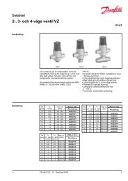
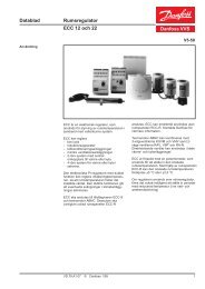
Hydronic module (option 116)The hydronic module option reduces the installation time.The heat pump is factory-equipped with the main hydroniccomponents required for the installation: screen filter, waterpump, safety valve, water pressure transducer, flow switch.The control system allows integration of system and waterpump protection devices (insufficient water flow rate, waterpressure, water flow rate etc.).The pump supplied with the hydronic module is a multispeedpump.An automatic pump start-up algorithm protects the heatexchanger and the hydronic module piping against frostdown to -10°C outside air temperature, as standard. Ifnecessary, increased frost protection down to -20 °C ispossible by adding heaters to the hydronic module piping(see option 42).The hydronic module option is integrated into the heatpump without increasing its dimensions and saves the spacenormally used for the water pump.Hydronic module141415211616Legend172217 20Typical hydronic circuit diagram18 1919Components of the unit and hydronic module1 Victaulic screen filter2 Pressure sensorNote: Gives pump suction pressure information (see installation manual)3 Safety valve4 Water drain valve5 Shut-off valve6 Water pump7 Temperature sensors, BPHE inletNote: Gives heat exchanger entering temperature information (see installation manual)8 Pressure gaugeNote: Allows measuring of the pump suction pressure, the pump leaving pressure and the heatexchanger leaving pressure9 Temperature sensor, BPHE outletNote: Gives heat exchanger leaving temperature information (see installation manual)10 Automatic air vent11 Flow switch12 Plate heat exchanger frost protection heater13 Plate heat exchangerInstallation components14 Temperature probe well15 Air vent16 Flexible connection17 Shut-off valve18 Screen filter (obligatory for a unit without hydronic module)19 Pressure gauge20 Water flow control valve21 Charge valve22 Frost protection bypass valve (when shut-off valves [17] are closed during winter)--- Hydronic module (unit with hydronic module)123 6411 10Notes:• Units without hydronic module (standard units) are equipped with a flow switch and two temperaturesensors (7 and 9).• For units equipped with hydronic module, the pressure sensor located upstream of the pump toprevent cavitation is installed on a connection without Schraeder valves. Depressurise and drainthe system before any intervention.579554841312Physical and electrical data, units with hydronic module<strong>AW05</strong> <strong>022</strong> 030 035 045 055 075 <strong>105</strong>Operating weight*Unit with hydronic module kg 349 403 436 524 549 926 1044Hydronic moduleMaximum operating pressure kPa 400 400 400 400 400 400 400Water filterVictaulic screen filter<strong>Pumps</strong>Water pump TOP-S 25 TOP-S 25 TOP-S40 TOP-S40 TOP-S40 TOP-S50 TOP-S50Shaft power input kW 0.18 0.18 0.35 0.35 0.35 0.45 0.45Power input** kW 0.42 0.42 0.63 0.63 0.63 0.95 0.95Nominal operating current draw A 0.4 0.4 0.6 0.6 0.7 1.3 1.5Maximum current draw at 400 V*** A 0.8 0.8 1.3 1.3 1.3 1.7 1.7Water connections (with hydronic module)Connections inch 1-1/4 1-1/4 1-1/2 1-1/2 1-1/2 2 2Outside diameter mm 42.4 42.4 48.3 48.3 48.3 60.3 60.3* Weight shown is a guideline only. To find out the unit refrigerant charge, please refer to the unit nameplate.** To obtain the maximum power input for a unit with hydronic module, add the maximum unit power input to the pump power input.*** To obtain the maximum operating current draw for a unit with hydronic module, add the maximum unit current draw to the pump current draw.VDGFG10211
Units with fans with available pressure for indoor installation(option 11)This option applies to <strong>AW05</strong> units installed inside thebuilding in a plant room. For this type of installation the coldair leaving the air-cooled evaporators is discharged by thefans to the outside of the building, using a duct system.The installation of a duct system at the air evaporatordischarge line causes a pressure drop due to the resistancecaused by the air flow.Therefore more powerful fan motors than those used for thestandard units are installed in the units with this option. Foreach installation of a unit installed inside a plant room theduct pressure drops differ, depending on the duct length,duct section and direction changes.<strong>AW05</strong> units equipped with fans with available pressure aredesigned to operate with air discharge ducts with maximumpressure drops of 100 Pa.Fan discharge connectionA square flange is supplied mounted on the unit. Anavailable standard round flange can easily be installed at thefan discharge, if the installer prefers the use of a roundconnection duct.The unit is supplied with a grille on the discharge side. Thisgrille has to be removed before connection to the ductsystem.It is advisable to make the connection to the duct systemwith a flexible sleeve. If this recommendation is not observed, alot of vibration and noise may be transmitted to the buildingstructure.Applicable rules for units incorporated into an air ductsystemEnsure that the suction or discharge inlets are not accidentallyobstructed by the panel positioning (e.g. low return oropen doors etc.).Electrical data for <strong>AW05</strong> units with option 11<strong>AW05</strong> - units with option 11 (without hydronic<strong>022</strong> 030 035 045 055 075 <strong>105</strong>kit)Power circuitNominal power supply V-ph-Hz 400-3-50Voltage range V 360-440Control circuit supply24 V, via internal transformerMaximum start-up current (Un)*Standard unit A 107,1 <strong>105</strong>,1 133,5 173,5 193,5 159,5 226,5Unit with electronic starter option A 58,6 57,6 72,5 93,3 103,7 106,5 147,5Unit power factor at maximum capacity** 0,82 0,82 0,82 0,82 0,82 0,82 0,82Maximum unit power input** kW 9,8 12,7 14 15,7 17,9 28 35,9Nominal unit current draw*** A 16,4 19 22,3 25,3 30 43,9 59,3Maximum unit current draw (Un)**** A 18,5 23,7 26,5 29,5 33,5 52,3 66,3Maximum unit current draw (Un-10%)† A 23,2 30,5 34,3 38,5 44,1 67,9 87,5Customer-side unit power reserveCustomer reserve at the 24 V control power circuitShort-circuit stability and protectionSee table on the next page* Maximum instantaneous start-up current (maximum operating current of the compressor + fan current + locked rotor current of the compressor).** Power input, compressor and fan, at the unit operating limits (saturated suction temperature 10°C, saturated condensing temperature 65°C) and nominal voltage of 400 V (data given on the unit nameplate).*** Standardised Eurovent conditions: condenser entering/leaving water temperature = 40°C/45°C, outside air temperature db/wb = 7°C/6°C.**** Maximum unit operating current at maximum unit power input and 400 V (values given on the unit nameplate).† Maximum unit operating current at maximum unit power input and 360 V.12 VDGFG102
Dimensions/clearances, <strong>AW05</strong> units with option 11<strong>AW05</strong> <strong>022</strong>-035 units with and without hydronic module111013273001371128010001000112210001000LegendAll dimensions are in mmRequired clearances for air flowRecommended space for maintenanceWater inletWater outletAir outlet, do not obstructControl boxPower cable connectionNOTES:A Non-certified drawings.Refer to the certified dimensional drawings supplied with the unit or available on request, whendesigning an installation. For the location of fixing points, weight distribution and coordinates ofthe centre of gravity refer to the certified dimensional drawings.B In multiple-unit installations (maximum four units), the side clearance between the units shouldbe increased from 1000 to 2000 mm.C The height of the solid surface must not exceed 2 m.VDGFG10213
Dimensions/clearances, <strong>AW05</strong> units with option 11 (continued)<strong>AW05</strong> 045-055 units with and without hydronic module11142079300137110001100012100021000LegendAll dimensions are in mmRequired clearances for air flowRecommended space for maintenanceWater inletWater outletAir outlet, do not obstructControl boxPower cable connectionNOTES:A Non-certified drawings.Refer to the certified dimensional drawings supplied with the unit or available on request, whendesigning an installation. For the location of fixing points, weight distribution and coordinates ofthe centre of gravity refer to the certified dimensional drawings.B In multiple-unit installations (maximum four units), the side clearance between the units shouldbe increased from 1000 to 2000 mm.C The height of the solid surface must not exceed 2 m.14 VDGFG102
Dimensions/clearances, <strong>AW05</strong> units with option 11 (continued)<strong>AW05</strong> 075-<strong>105</strong> units with and without hydronic module2100 227330013711000110001 2100021000LegendAll dimensions are in mmRequired clearances for air flowRecommended space for maintenanceWater inletWater outletAir outlet, do not obstructControl boxPower cable connectionNOTES:A Non-certified drawings.Refer to the certified dimensional drawings supplied with the unit or available on request, whendesigning an installation. For the location of fixing points, weight distribution and coordinates ofthe centre of gravity refer to the certified dimensional drawings.B In multiple-unit installations (maximum four units), the side clearance between the units shouldbe increased from 1000 to 2000 mm.C The height of the solid surface must not exceed 2 m.VDGFG10215
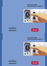
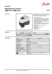
Available static system pressurePlate heat exchanger pressure drop - for pure water at 20°C<strong>AW05</strong> <strong>022</strong>-045<strong>AW05</strong> 055-<strong>105</strong>3050254403Pressure drop, kPa201510123Pressure drop, kPa30201251000 1 2 3 4 5Water flow rate, l/s1 <strong>AW05</strong> <strong>022</strong>2 <strong>AW05</strong> 0303 <strong>AW05</strong> 0354 <strong>AW05</strong> 04500 2 4 6 8 10Water flow rate, l/s1 <strong>AW05</strong> 0552 <strong>AW05</strong> 0753 <strong>AW05</strong> <strong>105</strong>16 VDGFG102