What is a Smart Drive? - Windenergy
What is a Smart Drive? - Windenergy
What is a Smart Drive? - Windenergy

Create successful ePaper yourself
Turn your PDF publications into a flip-book with our unique Google optimized e-Paper software.
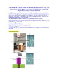
Manuals/Articles from ecoinnovation.co.nz<strong>What</strong> <strong>is</strong> a <strong>Smart</strong> <strong>Drive</strong>?F<strong>is</strong>her & Paykel <strong>Smart</strong> <strong>Drive</strong> Washing MachinesD<strong>is</strong>claimerSystems running on 60 volts and lower cannot, under normal circumstances,cause death in humans by electrocution. When freely spinning, <strong>Smart</strong> <strong>Drive</strong>units can produce over 1500 volts, and have the potential to deliver a lethalcurrent through the human bExtreme care must be taken to ensure that no contact <strong>is</strong> made with thesehigh voltages.EcoInnovation accepts no responsibility for any damage, injury or deathresulting from working on <strong>Smart</strong> <strong>Drive</strong> washing machine motors. It <strong>is</strong> yourresponsibility to ensure your safety and the safety of others that may comeinto contact with the generation unit.For more information v<strong>is</strong>it www.ecoinnovation.co.nz 1
Manuals/Articles from ecoinnovation.co.nzIntroduction:Th<strong>is</strong> introduction <strong>is</strong> intended to give an overview of the use of <strong>Smart</strong> <strong>Drive</strong> motors asgenerators in renewable energy systems. In contains an overview of results for 18<strong>Smart</strong> <strong>Drive</strong> generator options at 12/24/48 volts. For detailed information on how toreconnect a <strong>Smart</strong> <strong>Drive</strong> you will need to purchase the EcoInnovation <strong>Smart</strong> <strong>Drive</strong>manual.Advantage of a <strong>Smart</strong> drive:· Low speed generator due to large diameter· Brushless design· Low cost and widely available· Generator windings cannot be burnt out· Very efficient· Easily converted for different voltages· Large stainless steel shaft for easy mounting· Good corrosion res<strong>is</strong>tance<strong>Smart</strong> <strong>Drive</strong> Parts you need to findThe motor compr<strong>is</strong>es the following components:· 25m Stainless Steel shaft· Aluminum bearing holder· Stator (3 types available)· Magnetic Rotor (2 types available)· 4 fixing screws· 2 stator washers· 1 large flat washerFor more information v<strong>is</strong>it www.ecoinnovation.co.nz 3
Renewable Energy SystemsManuals/Articles from ecoinnovation.co.nzThe above diagram shows the main components in a Renewable Energy system.· <strong>Smart</strong> <strong>Drive</strong> wind turbine· <strong>Smart</strong> <strong>Drive</strong> turgo turbine· Photo Voltaic panels (PV)· Solar hot water heating· Battery bank· Inverter – converts battery dc power to 230 volt ac for normal house use· Regulator – controls battery charging and diverts power not required to hotwaterHydro <strong>is</strong> the most cost effective; a single Pelton or turgo turbine can generate all thepower that an energy efficient house needs. An off grid house without hydro willnormally need both a wind and solar PV system.If you want Renewable Energy to succeed, establ<strong>is</strong>h your house to be energyefficient:· Good energy efficient refrigeration· Compact florescent lights· LCD flat screen TV and computer (preferred)· Good insulation and double glazing with passive solar heating· Good energy efficient habits· LPG cooking· Sparing use of electric appliances that produce heat· Solar hot water heating with wood fire (or LPG gas) back upFor more information v<strong>is</strong>it www.ecoinnovation.co.nz 4
Manuals/Articles from ecoinnovation.co.nzRemove the cap from the top of the agitator, reach inside and undo the plastic nutthat holds the agitator onto the shaft. Remove the agitator then undo the screws onthe retaining ring.You can now remove the stainless steel bowl from within the plastic outer bowl.Turn the unit over and work from the bottom, remove the magnetic plastic rotor. Itshould look like the picture below.Undo the four fixing screws that hold the copper wire wound stator onto the bearingassembly; you can now cut out the bearing assembly from the plastic bowl with asaber saw. If you don’t have a saber saw you could hire one. The other way wouldbe to use a jig saw to cut the bottom off the plastic bowl and then use a band saw tocut the bearing assembly from th<strong>is</strong> piece. Res<strong>is</strong>t the temptation to use a chain saw;it <strong>is</strong> not a good idea.The cut bearing assembly should look like th<strong>is</strong>:For more information v<strong>is</strong>it www.ecoinnovation.co.nz 6
Manuals/Articles from ecoinnovation.co.nzThe pictures show the rough cut bearing assembly viewed from both ends, and thenthe same view after the unit has been machined on a lathe. Note that the seal hasbeen removed and the plastic machined down to expose the aluminum fixingchannels. Th<strong>is</strong> allows the unit to be fixed to a mounting surface.EcoInnovation removing bearing assembliesRecycling at EcoInnovationRough cut bearing assemblies by the 100’scleaned up and ready to makeinto products.Bearing assembliesdirect from F & PFor more information v<strong>is</strong>it www.ecoinnovation.co.nz 7
Manuals/Articles from ecoinnovation.co.nzEcoInnovation shafts and bearing assemblies – just a few and the manythousand in stockMachining the bearing assembly plastic housingTo machine on a lathe, put the shaft into the 3jaw lathe chuck, slide on the bearingassembly with the four fixing screws half in, so that the screws rest in between thejaws of the chuck. When the lathe <strong>is</strong> started the bearing assembly will rotate withthe shaft and can be machined down. Take only small cuts otherw<strong>is</strong>e you will shearoff the fixing screws from the bearing housing. For production work, make adedicated jig to hold the rough cut bearing holders securely so that large cuts can bemade.Condition of unitsThe <strong>Smart</strong> <strong>Drive</strong> units you manage to locate may not be in excellent condition. It <strong>is</strong>fairly common on these units for radial cracks (like spokes on a wheel) to haveformed in the plastic housing of the copper wound stator. To date they do not seemto be a problem, in a washing machine application the motor stator <strong>is</strong> subjected torepeated high torque reversals (not the case in renewable energy applications). Thecracks are made by the high torque reversals and temperature changes in the motor.The cracks form but generally do not get any worse. We have never had a unit failyet due to a cracked stator. We sell cracked units in our invertors kits at a very goodprice, if you want to get your hands on a the complete h<strong>is</strong>tory of the <strong>Smart</strong> <strong>Drive</strong> inone hit then the inventors kit <strong>is</strong> the way to go. All other units sold by EcoInnovationare in excellent condition with up to 1 hairline crack or no cracks present in the rotor.You pay a little more for them.For more information v<strong>is</strong>it www.ecoinnovation.co.nz 8
Manuals/Articles from ecoinnovation.co.nzTypical crack on an inventors kit statorBearing replacementThe bearings are easy and cheap to replace. To replace bearings knock the old onesout from the inside (use a length of steel rod or old bolt) and press the new ones intoplace, use a mallet to tap them fully home. Suggest you thoroughly clean the newbearings and housing surface and apply a small amount of Loctite onto the surfacesprior to assembly.Spinning of shaft in bearingsAfter a number of early failures, EcoInnovation became aware that in order toprevent the bearing spinning on the shaft <strong>is</strong> it absolutely necessary to loctite theshaft onto the bearings. Remember to thoroughly clean the surface to be glued first.Th<strong>is</strong> prevents the bearing from spinning which would otherw<strong>is</strong>e damage the shaftleading to m<strong>is</strong>alignment of the stator and rotor.Another good tip <strong>is</strong> to lightly knurl the bearing surface on a lathe. Th<strong>is</strong> roughens thesurface and provides good adhesion for the loctite. Knurling also increases theoutside diameter so the fit changes from a clearance fit to an interference fit and theshaft will need to be tapped into the bearing with a mallet. Th<strong>is</strong> <strong>is</strong> adv<strong>is</strong>able onhighly loaded shafts where there <strong>is</strong> significant side loading from a chain or V belt.For more information v<strong>is</strong>it www.ecoinnovation.co.nz 9
Manuals/Articles from ecoinnovation.co.nzIf you do forget to do th<strong>is</strong> and the shaft spins in the bearing, if the damage <strong>is</strong> onlyminor to the shaft you can dot punch to ra<strong>is</strong>e the bearing surface, then loctite andtap the bearing on with a mallet, th<strong>is</strong> usually fixes the problem. It pays to loctite itfirst. EcoInnovation can supply replacement shafts very cost effectively if required.Dealer EnquirersEcoInnovation has in stock hundreds of <strong>Smart</strong> <strong>Drive</strong>s and are open to d<strong>is</strong>cussion onvolume orders of <strong>Smart</strong> <strong>Drive</strong>s to individuals or companies w<strong>is</strong>hing to make theirown Renewable Energy products with them. We usually send a sample <strong>Smart</strong> <strong>Drive</strong>airfreight at cost to an interested company, quantity orders would then be aminimum of 50 units sent by sea freight. All units are checked and cleaned prior tod<strong>is</strong>patch and are sold in as new condition. A significant d<strong>is</strong>count <strong>is</strong> offered on suchorders.Testing of <strong>Smart</strong> <strong>Drive</strong>s at EcoInnovationEcoInnovation tested <strong>Smart</strong> <strong>Drive</strong>s on a modified lathe that was fitted with a variablespeed drive. The power of the driving motor limited the test results to 600700 Wattsof output. However, the performance trend has been establ<strong>is</strong>hed by these tests andit <strong>is</strong> possible to extrapolate th<strong>is</strong> trend to estimate the performance at high rpm’s. The<strong>Smart</strong> <strong>Drive</strong> rotor <strong>is</strong> not balance and runs very smoothly in the 11200 rpm range.Vibrations can be detected above 1200 rpm and the magnetic rotor should bebalance above th<strong>is</strong> speed. In the 12001800 rpm range guard against rotor failureand cover the <strong>Smart</strong> <strong>Drive</strong> in case of failure. Th<strong>is</strong> tends to apply to engine driven<strong>Smart</strong> <strong>Drive</strong>s and highspeed water turbine applications. In the wind turbineapplications ensure your maximum rpm <strong>is</strong> kept under 1800rpm and that the stator <strong>is</strong>balanced.Tests were conducted on a simulated 12/24/48 volt battery system with Xantrex C40charge controller maintaining system voltage at 13.8/27.6/55.2 volts respectively.The test results accurately represent the performance of a <strong>Smart</strong> <strong>Drive</strong> connecteddirectly to a battery bank at constant voltage. The tests included rectification lossesand the efficiency graphs should be used to indicate the most suitable unit for aparticular application.EcoInnovation <strong>is</strong> currently having more tests done using only 36 fingers of the <strong>Smart</strong><strong>Drive</strong> and including the latest type four (cogfree 36 finger) design. The 36fingeroption results in many different reconnection options not available if all 42 fingersare used. These tests will generate over 1000 data sets and the information will beavailable for sale on CD only.Maximum Power Point Trackers (MPPT)The technology behind MPPT <strong>is</strong> likely to revolutionize the use of generators in windand hydro applications in the future. To date MPPT’s are too expensive for the DIYenthusiast. These units allow the generator to run at its optimum power point whiledelivering the voltage required to your battery bank. In effect they have the ability tomatch the generator to the application for you. In steady state hydro applicationsth<strong>is</strong> <strong>is</strong> not required but in wind turbine applications could result in significantincreased output of the turbine. EcoInnovation <strong>is</strong> keeping a close eye on suchdevelopments as in time it will hopefully become more cost effective.For more information v<strong>is</strong>it www.ecoinnovation.co.nz 10
Manuals/Articles from ecoinnovation.co.nzThe other advantage of MPPT <strong>is</strong> that you can generate a much higher voltage thanyou require at the battery end to save on cabling losses. There are a number ofhydro schemes remote from the battery banks that do just th<strong>is</strong>. A MPPT at over$1000 <strong>is</strong> still much more expensive that using 3 x toroidal transformers to do thesame job. Transformers require much more skill in setting up but cost less than $300and they are less sensitive to being accidentally damaged by a high voltage spike. AMPPT would be more efficient at about 95% compared to 80% for 3 transformers.Transformer Applications<strong>Smart</strong> <strong>Drive</strong>s are high frequency 3 phase generators, the frequency of the unit =rpm/2.15. <strong>Smart</strong> <strong>Drive</strong>s running at 500 rpm will have a frequency of 232 Hz. Unitsrunning at maximum power of 1.4 kW can put out over 700 Hz, which <strong>is</strong> too high fornormal off the shelf transformers.EcoInnovation has developed a transformer application using 3 toroidal transformers,these operate well at high frequencies and are cheap to purchase. It <strong>is</strong> possible using3 x 300 VA transformers to make a transformer pack capable of delivering 1.4 kW ofpower at 24 and 48 volts. The transformers will need good air circulation and a smallfan to ass<strong>is</strong>t cooling if pushed above the 900 VA rating.In setting up transformers you will be dealing with voltages in the 300500 voltrange so you need to be careful, we do not recommend that the DIY enthusiast workwith these higher voltages unless sufficiently skilled and qualified to do so.The transformer primaries can be connected in Star or Delta, as can the secondaries.The transformer will almost certainly have multiple primary and secondary taps. The<strong>Smart</strong> <strong>Drive</strong> can also be configured in Star or Delta and used with the 100S, 80S or60S stators in th<strong>is</strong> application. The typical configuration of th<strong>is</strong> setup <strong>is</strong> indicatedbelow:· 3 x Jaycar transformers 110/230 to 12/24· 230volt primary connected into star of delta· Secondary connected into star or delta· S <strong>Smart</strong> <strong>Drive</strong> in either star or deltaNote the 24volt tapping <strong>is</strong> used for 48volt systems (as the transformers arerunning above 230volt they were designed for) and the 12volt tapping for 24voltapplications.How to decide which model you to make or purchaseRefer to the attached <strong>Smart</strong> <strong>Drive</strong> Test Result Summary Graphs these are the first 6graphs. The test rig was not able to test the units beyond 600700 Watts of outputpower. By studying all test results it <strong>is</strong> possible to observe the trend and thereforemake fairly accurate estimates of the performance of <strong>Smart</strong> <strong>Drive</strong> above the 600700watt range tested.Further tests conducted by EcoInnovation indicate that the maximum power outputof a <strong>Smart</strong> <strong>Drive</strong> <strong>is</strong> in the region of 1.4 kW at 16001800 rpm. Th<strong>is</strong> was achieved an80SP unit connected to a 48volt battery bank.NotationFor more information v<strong>is</strong>it www.ecoinnovation.co.nz 11
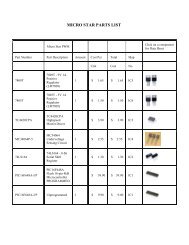
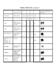
Manuals/Articles from ecoinnovation.co.nz· 160= 1.6mm wire diameter (30 turns/finger), you can rewire the units byhand if you w<strong>is</strong>h· 100= 1.0mm wire diameter, as used on first generation <strong>Smart</strong> <strong>Drive</strong>s· 80= 0.8mm wire diameter, as used on second generation <strong>Smart</strong> <strong>Drive</strong>s· 60= 0.6mm wire diameter, as used on third generation <strong>Smart</strong> <strong>Drive</strong>s· S = series connection, as standard· SP = half series half parallel connection· P = parallel connection<strong>Smart</strong> <strong>Drive</strong> generator dataModelWireDiametermmWireConfigurationNumberOfTurns perPhaseEffectiveWire Areamm^2ApproxCurrentRatingDelta/StarAmps100S 1.0 Series 616 0.79 12/8100 SP 1.0 Series/Parallel 88 5.50 84/56100 P 1.0 Parallel 44 11.00 168/11280 S 0.8 Series 1610 0.50 4.5/380 SP 0.8 Series/Parallel 230 3.52 32/2180 P 0.8 Parallel 115 7.04 64/4260 S 0.6 Series 2380 0.28 2/1.560 SP 0.6 Series/Parallel 340 2.00 14/1060 P 0.6 Parallel 170 4.00 28/20Changing from an S to a SP increases the wire area by 7 times and reduces thenumber of turns by 7 times. The operational performance will therefore be at seventimes the speed and good for 7 times the current. Likew<strong>is</strong>e, changing from an S to aP increases the wire area by 14 times and reduces the number of turns by 14 times.The operational performance will therefore be at 14 times the speed and good for 14times the current.The <strong>Smart</strong> <strong>Drive</strong> rotor provides excellent cooling; it <strong>is</strong> very unlikely overheating willbe a problem. The max currents indicated in the above table should not be taken asthe continuous operational current rating but the absolute maximum that the unitcan deliver. Continuous operation should be at less than the above values. Some ofthe values in the above table, 100SP for example, will require rpm’s much higherthan the maximum recommended running speed of 1800 rpm.It <strong>is</strong> possible to reconnect the units into more configurations. The nine optionspresented here have been adopted as the reconnections utilize all 42 fingers of theunit. Other options such as a third in series and twothirds parallel would use 36fingers and would yield a performance between the SP and P configuration. The<strong>Smart</strong> <strong>Drive</strong> units can therefore be tailored to you exact requirements.The unit you manage to obtain will have a certain wire size. If you locate a unit with0.8mm wire size then th<strong>is</strong> unit <strong>is</strong> referred to as an 80S model. From th<strong>is</strong> model youcan make either an 80SP or 80P. You will need to decide which model you w<strong>is</strong>h tomake; th<strong>is</strong> will depend on the operational speed and power you require for yourFor more information v<strong>is</strong>it www.ecoinnovation.co.nz 12
Manuals/Articles from ecoinnovation.co.nzapplication. You should peruse the performance graphs in order to determine th<strong>is</strong>.Refer to the summary graphs for all models grouped by voltage 12/24/48.Decide which voltage system you intend to use. Avoid 12volts if possible as suchsystems have high inherent losses. Most countries telephone exchanges are run on48volt systems. These telephone companies are a good source of equipment suchas second hand batteries, charger/rectifier sets (for generator charging your batterybank), cabling, inverters, cabinets, meters, and on occasions PV panels. If youchoose a 48volt system then there <strong>is</strong> a good chance you can scrounge retiredequipment from them. For these reasons EcoInnovation installs predominantly 48volt systems. Also 48volt systems have higher generator efficiencies and fewerlosses in cabling and rectification.12 and 24volt systems are very common and the cheaper type square waveinverters from Taiwan are readily available at these voltages.Once you have decided the system voltage, you need to select a performance curvethat meets the requirements of your application.The performance of the units can be tuned by packing the magnetic rotor up fromthe fully home position; th<strong>is</strong> reduces the magnetic field strength and increases theoperating speed on the units.The following examples should ass<strong>is</strong>t you in selecting the correct <strong>Smart</strong> <strong>Drive</strong> foryour application.Star and Delta Connections<strong>Smart</strong> drive motors are wound with three phases, you will notice 6 connections on a<strong>Smart</strong> <strong>Drive</strong> stator these are the two ends of each phase.Many readers will be unaware of the two types of connection that 3phase motorsand generators can be configured into: theses are commonly referred to as Star orDelta. How the unit <strong>is</strong> connected has a significant bearing on the operatingperformance of the units, therefore each unit can be configured to have twooperating points. These configurations are illustrated below. The copper windingsthat make up each phase (14 fingers on a <strong>Smart</strong> <strong>Drive</strong> stator) are illustrated belowin the Star and Delta configuration. All <strong>Smart</strong> <strong>Drive</strong>s as connected in F<strong>is</strong>her & Paykelwashing machines are connected in Star. Th<strong>is</strong> point <strong>is</strong> easy to identify as a 3pronged brass clip forms the star point as shown below.For more information v<strong>is</strong>it www.ecoinnovation.co.nz 13
<strong>Smart</strong> <strong>Drive</strong> Star PointManuals/Articles from ecoinnovation.co.nzStar ConnectionDelta ConnectionFirst Generation stators (100S Star units)These units can be recognized quickly by the wire diameter used to wind the stator.It <strong>is</strong> approximately 1.00mm diameter and Series wound in Star hence the name100S Star.For more information v<strong>is</strong>it www.ecoinnovation.co.nz 14
Manuals/Articles from ecoinnovation.co.nzRes<strong>is</strong>tance of each phase = 1.0 ohmsSecond Generation stators (80S Star units)These units can be recognized quickly by the wire diameter used to wind the statorand their very tidy appearance. It <strong>is</strong> approximately 0.80mm diameter and Serieswound in Star hence the name 80S Star.Res<strong>is</strong>tance of each phase = 5.8 ohmsThird Generation stators (60S Star units)These units can be recognized quickly by the wire diameter used to wind the stator.It <strong>is</strong> approximately 0.60mm diameter and Series wound in Star hence the name60S Star.For more information v<strong>is</strong>it www.ecoinnovation.co.nz 15
Manuals/Articles from ecoinnovation.co.nzRes<strong>is</strong>tance of each phase = 15.2 ohmsType One and type Two rotorsThe early type one rotors are very d<strong>is</strong>tinctive with 56 separate magnets. Theserotors are commonly found on washing machines that have 100S stators inside. Thetype two rotors appear to have 14 large magnets, th<strong>is</strong> however <strong>is</strong> an illusion, aswithin each magnet there are in fact 4 separate magnets.Type 1 rotor (old design)Type 2 rotor (latest design)3 Phase RectificationA <strong>Smart</strong> <strong>Drive</strong> <strong>is</strong> a 3phase alternator. It has to be for it to be for brushless design.For DC output you need to use a 3phase rectifier. You can either buy one or makeone yourself. Singlephase rectifier blocks are very common. From three of theseblocks you can make a 3 phase rectifier which <strong>is</strong> less expensive than buying adedicated 3 phase unit. Car alternators also have inside them 3 phase rectifiers andshops that supply car alternators can supply you.For more information v<strong>is</strong>it www.ecoinnovation.co.nz 16
Manuals/Articles from ecoinnovation.co.nzAutomotive type Electrical component type DIY from 3single phase rectifiersOn the automotive type unit shown the heat sinks are the positive and negativeterminals, the three AC terminals are clearly shown.Electrical component 3 phase rectifiers can be expensive in the large sizes; thesehave 5 terminals as shown.DIY rectifiers you can make yourself with 3 singlephase rectifiers at shown. Solderall the positives and all the negatives together and each phase onto the two AC pinson each single rectifier block.<strong>Smart</strong> <strong>Drive</strong> ReconnectionsAfter many years of experimenting with <strong>Smart</strong> <strong>Drive</strong> motors for use as generatorsEcoInnovation has developed a method of reconnection that <strong>is</strong> relatively straightforward, and provides secure connections with the option to finally connect the statorinto either Star or Delta. You will need to purchase our reconnection manual toobtain how to do th<strong>is</strong> and a full set of test graphs. A selection of a few of thesegraphs follow.<strong>Smart</strong> <strong>Drive</strong> Test Result Summary Graphs24 volt Star & DeltaFor more information v<strong>is</strong>it www.ecoinnovation.co.nz 17
Manuals/Articles from ecoinnovation.co.nz24V Star700Output Power60050040030020010000 200 400 600 800 1000RPM160S100SP100S80S80SP80P60S60SP60PTest Result Detailed GraphsDiamond markers Power (Watts), Square markers Efficiency (%)80SP Stator – 24 volt80SP 24V Star700600Output Power50040030020010000 200 400 600 800 1000RPMConclusionThe retasking of <strong>Smart</strong> <strong>Drive</strong>s as generators can be anenvironmentallyfriendly process, recycling a component that wouldotherw<strong>is</strong>e end up in landfill, creating clean, renewable energyefficiently, and decreasing the user’s dependence on fossil fuels. All ofus here at EcoInnovation w<strong>is</strong>h you good luck with your project.For more information v<strong>is</strong>it www.ecoinnovation.co.nz 18