high power electromagnetic impulse
high power electromagnetic impulse
high power electromagnetic impulse

You also want an ePaper? Increase the reach of your titles
YUMPU automatically turns print PDFs into web optimized ePapers that Google loves.
ABSTRACT<br />
SANDIA NATIONAL LABORATORIES' HIGH POWER<br />
ELECTROMAGNETIC IMPULSE SOURCES<br />
L. F. Rinehart*, M. T. Buttram, G. J. Denison, J. M. Lundstrom,<br />
W. R. Crowe, J. F. Aurand, P. E. Patterson<br />
Dept. 1248<br />
Sandia National Laboratories<br />
Albuquerque N.M. 87 185 USA<br />
Three <strong>impulse</strong> sources have been developed to cover a wide range of peak <strong>power</strong>,<br />
bandwidth and center frequency requirements. Each of the sources can operate in single shot, rep-<br />
rate, or burst modes. These devices are of rugged construction and are suitable for field use. This<br />
paper will describe the specifications and principals of operation for each source.<br />
The sources to be described are: SNIPER (Sub-Nanosecond f@ulsE Mator), a coaxial<br />
Blurnlein pulser with an in-line (series) peaking switch; EMBL Enantiozorphic mumlein), a<br />
bipolar parallel plate Blumlein with a crowbar type (parallel) peaking switch; and the LC0 (L-C<br />
Oscillator) a spark-switched L-C oscillator with damped sinusoidd output.<br />
SNIPER and EMBL are ultra-wideband (1LTWB) sources which produce a very fast <strong>high</strong><br />
voltage transition. When Merentiated by the antenna, an <strong>impulse</strong> whose width corresponds to the<br />
transition time is radiated. The LC0 operates with a center frequency up to 800 MHz and up to<br />
100 MHz bandwidth. Because the LC0 output is relatively narrow band, <strong>high</strong> gain antennas may<br />
be employed to produce very <strong>high</strong> radiated field strengths.<br />
The UWB SNIPER Source<br />
SNIPER is a 250 kV ultra-wideband source producing 1.25 GW peak <strong>power</strong> into a 50<br />
ohm load. The oil-insulated Blumlein is switched by a hydrogen gas spark gap. Hydrogen exhibits<br />
very fast dielectric recovery1, allowing &I1 <strong>power</strong> operation at >1 kHz and reduced <strong>power</strong> (<strong>power</strong><br />
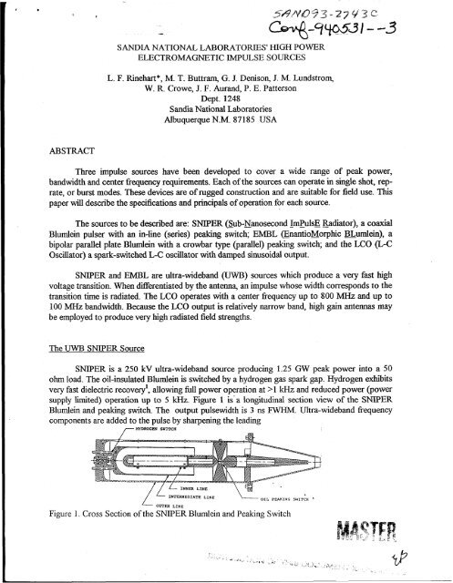
supply limited) operation up to 5 kHz. Figure 1 is'a longitudinal section view of the SNPER<br />
Blumlein and peaking switch. The output pulsewidth is 3 ns FWHM. Ultra-wideband 6equency<br />
components are added to the pulse by sharpening the leading<br />
7 HYDROGEN SWITCH<br />
NTERXEDIATE LINE<br />
OIL PEAKING SWITCH '<br />
Figure 1. Cross Section of the SNIPER Blumlein and Peaking Switch
DISCLAIMER<br />
This report was .prepared as an account of work sponsored<br />
by an agency of the United States Government. Neither<br />
the United States Government nor any agency thereof, nor<br />
any of their employees, make any warranty, express or<br />
implied, or assumes any legal liability or responsibility for<br />
the accuracy, completeness, or usefulness of any<br />
information, apparatus, product, or process disclosed, or<br />
represents that its use would not infringe privately owned<br />
rights. Reference herein to any specific commercial<br />
product, process, or service by trade name, trademark,<br />
manufacturer, or otherwise does not necessarily constitute<br />
or imply its endorsement, recommendation, or favoring by<br />
the United States Government or any agency thereof. The<br />
views and opinions of authors expressed herein do not<br />
necessarily state or reflect those of the United States<br />
Government or any agency thereof.
DISCLAIMER<br />
Portions of this document may be illegible<br />
in electronic image products. Images are<br />
produced from the best available original<br />
document.
edge with a series peaking switch. The oil dielectric peaking gap in the center conductor of the<br />
coaxial Blumlein output sharpens the leading edge of the pulse to
Figure 3. SNIPER Blurnlein Output; A. Without Peaking Switch, B. With Peaking Switch<br />
High Power UWB E-L Source<br />
The EnantioMorphic (mirror image) aumlein, EMBL, operates at 750 kV to produce<br />
>I1 GW peak <strong>power</strong> into 50 ohms. EMBL is a four line, single switch arrangement of two<br />
oppositely charged parallel plate Blumleins. See Figure 4. The Blumleins are in a "Manred"<br />
configuration in which they would share a (fifth) ground line between them. The two lines would<br />
erect in opposite polarities with respect to this line. Since both the charging and output are<br />
bipolar, an actual ground line is unnecessary. Instead, the ground line is omitted and exists as a<br />
virtual ground plane. This plane is also a plane of symmetry, the two Blumleins being mirror<br />
images above and below it. Advantages of the parallel plate construction are that the switch<br />
geometry is simple and no balun is required to connect to an antenna.<br />
Charged Fired I<br />
Figure 4. Bipolar EMBL Blumlein with E Vectors Shown, A Line Charged, B. Line Erected<br />
An additional advantage of the EMBL design is the use of bipolar charging. Impulse<br />
sources have inherently small energy storage capacity. A very significant efficiency problem exists<br />
because the stray capacitance of the charging circuit can be equal to or greater than the energy<br />
storage capacitance of the source. So a large fraction of the energy is then stored in stray<br />
capacitance and wasted. With bipolar charging, full charge voltage only appears across the<br />
<strong>impulse</strong> source. All stray capacitances are charged to plus or minus 112 fill1 voltage. All else being<br />
equal, energy is stored in the strays at 1/4 th the rate of a unipolar charged device4.<br />
The device stores 50 to 75 Joules per shot, and rep-rate js <strong>power</strong> supply limited to -700<br />
Hz in 1 second bursts (40 kW ave. <strong>power</strong> during the burst).<br />
A typical EMBL Blumlein output pulse is 3.5 ns FWHM. The pulse is crowbarred at peak
voltage by a gas spark gap so that its' trailing edge is sharpened to
A typical schematic is represented in figure 53, in this case the component values are for a<br />
50 MHz center frequency. The most efficient antenna match is achieved when the L-C oscillators'<br />
characteristic impedan&, Zo, is much greater than Rs, the series loss (spark gap heating), and<br />
much less than Rp, the parallel loss (the antenna). The optimum characteristic impedance is on the<br />
order of 10 ohms6.<br />
I I<br />
'- 3" -1<br />
?'<br />
Capacitor Plate<br />
,300pf RP<br />
Figure 7. Cross Section of 700 MHz LC0 Figure 8. Schematic of a 50 MHz LC0<br />
At VHF and UHF frequencies, it may not be possible to construct the oscillator to<br />
withstand very <strong>high</strong> voltage (a few hundred kV) and keep the characteristic impedance as low as<br />
10 ohms. This is because at <strong>high</strong> voltage the requisite dielectric thickness and switch size force the<br />
inductance up. S i the charact&c impedance is Z,=(L/C)*? there is a trade-off between <strong>high</strong><br />
voltage capability and low impedance. If the oscillator impedance is too <strong>high</strong> it will be severely<br />
loaded by the antenna and Q may be very low.<br />
The center frequency of the unloaded oscillator is shifted downward by the series and<br />
parallel losses. As the R-L-C circuit approaches critical damping, Q lowers, and the frequency<br />
spectrum widens and shifts downward. This frequency shift is significant and becomes a design<br />
consideration when Q is low (say ~3)"'.<br />
In the case of our 700 MHz transmitter, the LC0 and dipole are situated at the focus of a<br />
parabolic cylinder sub-reflector, and the LCO/dipole and sub-reflector package is positioned at the<br />
focus of a larger (3.7 m diameter) parabolic dish. Overall gain for the system is 26 dBi with a<br />
12 degree (3 dB) beamwidth. The modulator, L-C oscillator, dipole, and sub-reflector are<br />
enclosed in a plastic box filled with insulating gas (SF6). The device can run for several minutes at<br />
>1 kHz rep-rate. With the large parabolic dish reflector it produces normalized boresight E-fields<br />
in excess of 400 kV/m. Figure 9 shows the radiated E-field and frequency spectrum.<br />
I_ -
Corona Losses on Antennas<br />
Corona exists near the surface of <strong>high</strong> voltage conductors and extends out to a distance<br />
where the electric fields fall below 30 kV/cm for atmospheric pressure air. Corona losses occur<br />
primarily because moving ions collide with neutral gas particles and increase the thermal energy of<br />
the gas8.<br />
When very <strong>high</strong> voltage is applied to the antenna, losses to corona loading can be<br />
surprisingly severe. Figure 10 shows how serious this problem can be. The EMBL pulser is<br />
connected to a 4 meter long TEM horn antenna with a 1.3 meter wide aperture. This antenna has<br />
a tapered solid plastic insulator in the feed section, so arc formation cannot occur without leaving<br />
direct evidence. We are assured that the losses are due only to corona and partial discharges.<br />
The horizontal axis in the figure represents the EMBL firing voltage which approximates<br />
voltage at the antenna terminals. The vertical axis represents the corresponding normalized<br />
radiated peak <strong>power</strong> density. The diamonds are data points with the antenna in air. The<br />
normalized <strong>power</strong> density at 750 kV operation is 350 h4w/rn2, an<br />
improvement of >loo% at the same voltage. The solid line in figure 10 shows normaliied <strong>power</strong><br />
density for a lossless system.<br />
-<br />
C\f I<br />
Voltage at Antenna Terminals (Volts)<br />
Figure 10. Radiated Power Loss to Corona Loading of the Antenna
SUMMARY<br />
Three <strong>impulse</strong> sources have been constructed and deployed for field testing. They produce<br />
normalized radiated electric fields as <strong>high</strong> as 400 kVlm with repetition rates as <strong>high</strong> as 1 kHz.<br />
Waveforms are either unipolar <strong>impulse</strong>s as in the case of SNIPER and EMBL, or a damped<br />
sinusoid for the LC0 source.<br />
References<br />
1. S. L. Moran and L. F. Rinehart, Voltage Recovery Time of Small Gas Spark Gaps, IEEE<br />
Transactions on Plasma Science, Dec. 1982, Vol. PS-10, No.4<br />
2. J. W. Ginn, D. N. Hendricks, and M. T. Buttram, Nanosecond Spark Gap Measurements,<br />
17th EEE Power Modulator Symposium, June 1986<br />
3. J. M. Proud and H. J. Huber, Picosecond Risetime Switch Study, Technical Report No.<br />
RADC-TR-67-400, Rome Air Development Center, August 1967<br />
4. L. F. Rinehart, M. T. Buttram, W. R Crowe, R. S. Clark, J. M. Lundstrom, P. E.<br />
Patterson, An Enantiomorphic Blumlein Impulse Generator, 20th IEEE Power Modulator<br />
Symposium, June 1992<br />
5. L. F. Rinehart, J. F. Aurand, J. M. Lundstrom, C. A Frost, M T. Buttram, P. E.<br />
Patterson, and W. R. Crowe, Development of UHF Spark-Switched L-C Oscillators, 9th IEEE<br />
Pulsed Power Conference, June 1993<br />
6. S. L. Moran, High-Repetition Rate L-C Oscillators, U.S. Naval Surface Weapons Center<br />
Technical Report, NSWCDL TR-3658, December 1977<br />
7. F. E. Terman, Radio Engineer's Handbook, pp. 145-148, McGraw-Hill, New York, 1943<br />
8. J. D. Cobine, Gaseous Conductors, Dover &blications, Inc. 180 Varick St., New York,<br />
N. Y., 10014, 1958