Service Bulletin A-101 Rev.G Aircraft Heater - Hartzell Engine ...
Service Bulletin A-101 Rev.G Aircraft Heater - Hartzell Engine ...
Service Bulletin A-101 Rev.G Aircraft Heater - Hartzell Engine ...

You also want an ePaper? Increase the reach of your titles
YUMPU automatically turns print PDFs into web optimized ePapers that Google loves.
C. Instructions: (cont’d)<br />
<strong>Service</strong> <strong>Bulletin</strong><br />
No. A-<strong>101</strong> <strong>Rev</strong>. G<br />
<strong>Aircraft</strong> <strong>Heater</strong> Upgrade to I-Series<br />
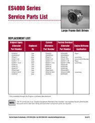
(4) Once the combustion tube assembly has been removed, It will be necessary to<br />
remove the combustion head assembly for modification. Remove the hardware<br />
and pull out the combustion head assembly. (Refer to Fig. 3.)<br />
Typical Combustion Tube Ass’y<br />
(To be replaced with IS tube)<br />
Combustion<br />
Head Ass’y<br />
Figure 3 - Combustion Tube & Combustion Head Ass’y<br />
Combustion<br />
Tube Ass’y<br />
(5) With the combustion head assembly removed, inspect for condition. If there<br />
appears to be any deformation, soft areas, or burn through, replace combustion<br />
head assembly. If not, clean per the appropriate steps in the applicable manual.<br />
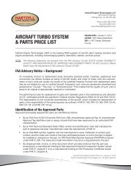
(6) Locate the combustion head anode as shown in Figure 4. Not all eligible B-Series<br />
heater combustion heads will have an anode rod installed. If no anode rod<br />
appears, steps 7 and 8 are not applicable.<br />
Spark Plug<br />
Ref. Location<br />
Typical Combustion Head Ass’y<br />
(for reference only)<br />
Combustion<br />
Head Anode<br />
To be Cut & Removed<br />
Figure 4 - Remove Combustion Head Anode<br />
(7) Mark the anode rod 0.25 inch from the wall where it is attached by weld and cut<br />
the rod off using a suitable tool.<br />
SB A-<strong>101</strong> Aug./95, <strong>Rev</strong>. G August 22/12<br />
Page 6 of 16 © 2012 - <strong>Hartzell</strong> <strong>Engine</strong> Technologies. - All rights reserved