LAB #2: Fun with DC Circuits - PhET
LAB #2: Fun with DC Circuits - PhET
LAB #2: Fun with DC Circuits - PhET

Create successful ePaper yourself
Turn your PDF publications into a flip-book with our unique Google optimized e-Paper software.
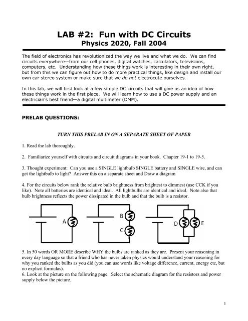
<strong>LAB</strong> <strong>#2</strong>: <strong>Fun</strong> <strong>with</strong> <strong>DC</strong> <strong>Circuits</strong>Physics 2020, Fall 2004The field of electronics has revolutionized the way we live and what we do. We can findcircuits everywhere—from our cell phones, digital watches, calculators, televisions,computers, etc. Understanding how these things work is interesting in their own right,but from this we can figure out how to do more practical things, like design and install ourown car stereo system or make sure that we do not electrocute ourselves.In this lab, we will first look at a few simple <strong>DC</strong> circuits that will give us an idea of howthese things work in the first place. We will learn how to use a <strong>DC</strong> power supply and anelectrician’s best friend—a digital multimeter (DMM).PRE<strong>LAB</strong> QUESTIONS:1. Read the lab thoroughly.TURN THIS PRE<strong>LAB</strong> IN ON A SEPARATE SHEET OF PAPER2. Familiarize yourself <strong>with</strong> circuits and circuit diagrams in your book. Chapter 19-1 to 19-5.3. Thought experiment: Can you use a SINGLE lightbulb SINGLE battery and SINGLE wire, and canget the lightbulb to light? Answer this on a separate sheet and Draw a diagram4. For the circuits below rank the relative bulb brightness from brightest to dimmest (use CCK if youlike). Note all batteries are identical and ideal. All lightbulbs are identical and ideal. Note also thatbulb brightness reflects the power dissipated in the bulb and that the bulb is a resistor.5. In 50 words OR MORE describe WHY the bulbs are ranked as they are. Present your reasoning inevery day language so that a friend who has never taken physics would understand your reasoning forwhy you ranked the bulbs as you did (you can use words like voltage difference, current, energy etc, butno explicit formulas).6. Look at the picture on the following page. Select the schematic diagram for the resistors and powersupply below the picture.1
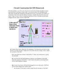
voltage source -->wire -->resistor -->(A)(B)(C)(D)(E)The Tools:2
-<strong>DC</strong> Power Supplyvoltagecurrentmetal connectorvoltagecoarsefinecurrent+On your bench:The two instruments you will use in this lab are a <strong>DC</strong>power supply and a digital multimeter. The <strong>DC</strong> powersupply produces a constant voltage, which can beadjusted anywhere from zero to 30 volts <strong>with</strong> the voltageknobs (coarse and fine) on the front panel. The powersupply has three output terminals: plus (red), minus(black), and ground (green). The ground terminal isalways at zero volts. In this experiment, the ground andminus terminals are tied together by a metal connectorso the minus terminal is also at zero volts. Both thecurrent and voltage produced by the power supply canbe read on meters on the front panel. Also on the frontpanel is a current-limit knob, which can be adjusted tolimit the maximum output current, to prevent damage tosensitive circuit elements. In this lab, the current knobhas been set and clamped in place so the power supplycannot produce more than about 0.6A current.The hand-held digital multimeter (DMM) is a wonderful little device which can be used tomeasure the voltage difference between any two points in a circuit, the current, and theresistance or capacitance of any circuit component(s). In this lab, we will use the DMM tomeasure both resistances and <strong>DC</strong> voltage differences. There are 2 wires attached to theDMM. One of the two wires always goes to the COM (common) terminal. To measureeither the voltage difference or the resistance, the second wire is attached to the “VΩ”input. In this lab, all our measurements will be <strong>DC</strong>, so the <strong>DC</strong>/AC switch (upper right)should always be in the <strong>DC</strong> position. The DMM has an alarm; it rings if you have wiresplugged into positions which conflict <strong>with</strong> the central knob’s position.The 2 wires attached to the DMM are called "needle probes". You can quickly measure thechange in voltage between any two points in a circuit by touching the points <strong>with</strong> theneedle probes.When measuring aresistance <strong>with</strong> a DMM,you must disconnect thesource of the resistancefrom any other devices,such as power supplies.Never try to measure theresistance of a resistorwhile it is still in a circuit.<strong>DC</strong>ΩV<strong>DC</strong> ACVMeasuring a resistance<strong>with</strong> the DMM.DMMYou will also be usingThe CircuitcomVΩneedle probes3
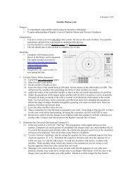
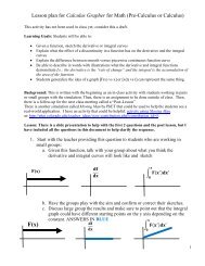
Construction Kit (CCK) Simulation:With the CCK you can quickly build and explore any circuit you want!You will be using laptop computers at your stations. When the simulation is started you are ready buildyour own circuits. Click and drag the icons (batteries, bulbs, resistors, etc) into the workspace. Thewires are automatically soldered (connected) together by touching the round ends. To decouple themright click. To change the values of the components, right click. You can look at things in a schematicview or a life-like viewIt comes <strong>with</strong>:• batteries <strong>with</strong> adjustable voltages• light bulbs <strong>with</strong> adjustable resistance• resistors <strong>with</strong> adjustable resistance• switches• wires• a volt meter which like the DMM can measure voltage differences betweenany two points in your circuit.• and, a current meterHelpful hints:• right click on junctions to disconnect• right click on components to view your options.•You cannot break the CCK, so go for it!PART I: UNDERSTANDING RESISTANCEYour goal of this part of the lab is the following: Figure out how to measure theresistance of various things using the tools in the CCK.In your play area select 5 resistors and adjust their values to be: one 1Ω, one 4Ω, two 50Ω, and one 100Ω. Add two light bulbs to your play area and adjust their resistance to be25Ω each.It is up to your lab group to create 2 different resistor combinations using some of the 5resistors and 2 light bulbs —both in series and in parallel. Draw a picture of each comboof resistors in your lab book, and predict the equivalent resistance of that combo. Buildthese resistor combinations in the CCK, and test your prediction by building anothersingle-resistor circuit <strong>with</strong> the equivalent resistance (<strong>with</strong>in 1Ω) and comparing the two.Do your two circuits have equivalent resistance? How can you tell?PART II: CIRCUIT BEHAVIORNow that you understand how to use the DMM, you will now use CCK to build a circuit andinvestigate its behavior.Using CCK, construct the circuit shown below, consisting of two light bulbs in series <strong>with</strong>the power supply (battery). (The resistor R will be added later). Slowly increase thebattery voltage until the bulbs are glowing, but not too bright. Predict what will happen tothe brightness of the bulbs when you place a R = 50Ω resistor in parallel <strong>with</strong> bulb <strong>#2</strong> as4
shown in the schematic. Go ahead and add in the resistor, and describe in your ownwords what happened and why.Measure the voltage difference across the light bulbs and resistor and verify that theymatch your prediction (i.e., if you know the power supply voltage and all the resistances,do the other voltages make sense?).Do the same thing for other resistor values and describe what happens in each case.RV1 2PART III: MEASURING RESISTANCE IN MULTIPLE WAYSIn Part I of this lab, you used CCK to test whether you had correctly predicted equivalentresistance. Go back to one of the circuits that you built in CCK in Part II. Using the toolsavailable in CCK, measure the resistance of the resistor in parallel <strong>with</strong> bulb <strong>#2</strong> <strong>with</strong>outusing the resistance readout setting in the program. Your group will have to figure out aclever way to do this using the tools available to you. Describe in detail how you wereable to accomplish this.Note: Besides not being able to use the resistance readout, make sure that the lightbulbs are still glowing when you take any measurements.5