AN EXPERIMENTAL STUDY IN UTILIZATION OF FLY ASH AS A ...
AN EXPERIMENTAL STUDY IN UTILIZATION OF FLY ASH AS A ...
AN EXPERIMENTAL STUDY IN UTILIZATION OF FLY ASH AS A ...

Create successful ePaper yourself
Turn your PDF publications into a flip-book with our unique Google optimized e-Paper software.
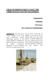
<strong>AN</strong> <strong>EXPERIMENTAL</strong> <strong>STUDY</strong> <strong>IN</strong> <strong>UTILIZATION</strong> <strong>OF</strong> <strong>FLY</strong> <strong><strong>AS</strong>H</strong> <strong>AS</strong> A COURSEAGGREGATES <strong>AN</strong>D QUARRY DUST <strong>AS</strong> F<strong>IN</strong>E AGGREGATES <strong>IN</strong> CONCRETEABSTRACTQuarry dust is a by-product obtainedduring crushing of granite rocks. Quarrydust can be an economic alternative to riversand. Common river sand is expensive dueto excessive cost of transportation fromnatural sources. Also large-scale depletionof these sources creates environmentalproblems. River sand is most commonlyused fine aggregate in the production ofconcrete poses the problem of acute shortagein many areas. Its continued usage hasstarted posing serious problems with respectto its availability, cost and environmentalimpact. In such a situation the Quarry rockdust can be an economic alternative to theriver sand.Granite aggregate is a vital elementin concrete and its extensive use results indestruction of hills causing geological andenvironmental imbalance. The concernabout the depletion of natural sources andthe effect on environment has particularlyfocused attention on possibility of usingaggregates from waste materials as analternative to naturally occurring materials.Fly ash is a by-product obtained from coalbased thermal power plants. It can be usedfor making artificial aggregates.In this study, it is proposed to 100%replacement of the fine aggregates by quarrydust and partial replacement (10%, 20% and30%) of coarse aggregates by fly ash coarseaggregates. A mix design was done for M30grade concrete by IS method. Fly ash coarseaggregates can be prepared by mixing flyash with cement and water. The variousproportions of cement and fly ash ratio of10:90, 15:85, and 20:80 were tried to get flyash aggregates. The best proportion isk.vinodh.civil III rd yearIFET college of engineeringfinalized based on the various properties offly ash coarse aggregates. The concretecubes and prisms were cast with partialreplacement of fly ash aggregates as coarseaggregates and 100 % quarry dust as fineaggregates. The compressive strength,flexural strength at 7 days and 28 days wereinvestigated.<strong>IN</strong>TRODUCTIONCommon river sand is expensive dueto excessive cost of transportation fromnatural sources. Also large scale depletion ofthese resources creates environmentalproblems. The river sand posses the problemof acute shortage in many areas, in suchsituation quarry dust can be an economicalternative to river sand. The environmentalimpacts of crushed stone aggregateextraction are a source of increasing concernin many parts of the country. The impactsinclude loss of forests, noise, dust, blastingvibrations and pollution hazards unplannedexploitation of rocks may lead to landslidesof weak and steep hill slopes. The concernabout the depletion of natural sources andthe effect on environment has particularlyfocused attention on possibility of use ofsynthetically produced (from wastematerials) aggregates as an alternative tonaturally occurring materials. Fly ash is awaste material obtained from thermal powerstation. It is available in plenty. It can beused in making artificial light weight coarseaggregates.The aggregates so prepared are known as flyash aggregates. These aggregates can beused in making light weight concrete. Thefly ash aggregate was light in nature and itsuse in concrete reduced the self weight of
the structure besides attaining better thermalMATERIALS USEDCement:In this study ordinary Portlandcement of 53 grade confirming to Indianstandard IS 12269-1987 was used.Natural Granite Aggregate:Locallyavailable crushed stone conforming tograded aggregate of nominal size 20 mm asper IS 383-1970 was used in thisexperimental work. Its physical propertiesare given in Table 2Sand:Locally available river sand ofgrading zone II confirming to IS 383-1970was used in this experimental work. Itsphysical properties are dealt with in Table 1.Quarry Dust: The Quarry Rock Dustobtained from local resource confirming tograding zone II of IS 383-1970 was used inthis experimental work. Its physicalproperties are dealt with in Table 1.insulation performance.Fly Ash: Fly ash (Class-C) obtained fromThermal power plant, Ennore conforming toIS 3812-1981 was used in this experimentalwork. The chemical composition of class-cfly ash is given in the table 3.Water:Portable drinking water having pHvalue of 7 and conforming to IS 456-2000was used for making concrete as well as forcuring the specimen.Fly Ash Coarse Aggregate:The Fly ashcoarse aggregates obtained from cement-flyash proportion 10:90, 15:85, 20:80 wereprepared and the best proportion wasfinalized based on aggregate impact andaggregate crushing values. The aggregatesthat are produced using finalized ratio wasused in concrete.PROPERTIES <strong>OF</strong> AGGREGATESTable 1.Physical Properties of Natural Sand and Quarry DustProperties Natural sand (IS383-1970) Quarry DustSpecific gravity 2.49 2.92Bulk density (Kg/m 3 ) 1671 1850Water absorption (%) 2.05 1.5Size (mm) Below 4.75 Below 4.75Sieve analysis Zone-II Zone-IITable 2. Physical Properties of Natural granite Aggregate and Fly ash Coarse Aggregate
PropertiesNatural granite Aggregate Fly ash Coarse Aggregate(IS 383-1970)Shape Angular SphericalSpecific gravity 2.66 1.41Bulk density (Kg/m 3 ) 1715 912Size (mm) 4.75mm to 20mm 4.75mm to 20mmWater absorption (%) 1.16 21Crushing value (%) 24.94 30.70Impact value (%) 23.86 22.52Table 3.Chemical Composition of Class-C Fly ashConstituent Percentage (%)Silica SiO 2 40 – 60Alumina Al 2 O 3 20 – 30Calcium Oxide CaO 5 – 30Ferric Oxide Fe 2 O 3 4 – 10LossIgnitionOnLOI 0 – 30PROPORTIONS FOR <strong>FLY</strong> <strong><strong>AS</strong>H</strong>AGGREGATESCement and fly ash are constituentsfor preparation of the aggregates. Also wateris the binder when it is added to increase theworkability. Three different proportions ofcement and fly ash such as 10:90, 15:85 and20:80 were tried.PREPARATIONS <strong>OF</strong> <strong>FLY</strong> <strong><strong>AS</strong>H</strong>AGGREGATESCement and fly ash were mixed inabove three proportions in a concrete mixer.The mixture is then transferred in to thepelletiser equipment in which the aggregatesare manufactured. Water was added to themix by adopting a water cement ratio of 0.3.The contents were thoroughly mixed in thedrum until the complete formation of fly ashaggregates. This method of formation of flyash aggregates is known as pelletisation.The fly ash aggregates and the pelletiser areshown in figure1 and figure2 respectively.DRY<strong>IN</strong>G <strong>AN</strong>D CUR<strong>IN</strong>G <strong>OF</strong> <strong>FLY</strong> <strong><strong>AS</strong>H</strong>AGGREGATESThe fly ash aggregates were takenout from the pelletiser and allowed to dry fora day. The dried aggregates were cured inthe water tank for 28 days.Fig 1. Fly Ash Aggregates
test and aggregate impact test wereconducted for these aggregates. Based onthe aggregate crushing value and impactvalue, the fly ash aggregate obtained fromthe ratio 15:85 was finalized.Fig 2. PelletiserSELECTION <strong>OF</strong> BEST PROPORTIONS<strong>OF</strong> <strong>FLY</strong> <strong><strong>AS</strong>H</strong> AGGREGATESThe cured aggregates of differentproportion are dried. The aggregate crushingTable 4.Crushing value and impact value of different proportion of fly ash aggregatesPropertiesImpactvalueCrushingvalueRATIO10:90 15:85 20:8023.18 22.52 22.5831.23 30.70 30.79MIX PROPORTIONMix design for M 30 Grade concrete was done by using IS method as per IS 10262-1982.Table 5.Conventional Concrete mix for M30 (IS 10262-1982)Cement(kg/m 3 )Sand(kg/m 3 )Coarse aggregate(kg/m 3 )Water(l/m 3 )435.41 525.28 1164.54 194.891 1.21 2.67 0.44Table 6. For 1m 3 of concreteMIXQuantityof Cement(kg)Water(kg)QuarryDust (kg)Coarse Aggregate (kg)GraniteAggregateFly AshAggregate(kg)
MIX 1(1:1.39:2.67)MIX 2(1:1.39:2.54)MIX 3(1:1.39:2.38)MIX 4(1:1.39:2.28)(kg)435.41 199.23 608.20 1164.46 0435.41 222.20 608.20 1014.30 93.07435.41 245.16 608.20 862.19 176.03435.41 268.14 608.20 712.68 279.22NOTE:MIX 1 - Concrete with 100% quarry dust,100% natural granite aggregate and 0% flyash aggregateMIX 2 - Concrete with 100% quarry dust,90% natural granite aggregate and 10% flyash aggregateMIX 3 - Concrete with 100% quarry dust,80% natural granite aggregate and 20% flyash aggregateMIX 4 - Concrete with 100% quarry dust,70% natural granite aggregate and 30% flyash aggregateAfter curing for required period thespecimens were tested using compressivetesting machine. The maximum load takenby specimen was recorded. Figure 3 showsthe typical compressive testing setup.Compressive strength is determined usingthe following formulaCompressive strength (MPa) = Maximumload (N) /cross sectional area (mm 2 )C<strong>AS</strong>T<strong>IN</strong>G <strong>OF</strong> TEST SPECIMENSThe concrete cubes of size 150mm x150mm x 150mm and concrete beams ofsize 100mm x 100mm x 500mm were cast todetermine the compressive strength andflexural strength of the concrete at 7 daysand 28 days. The specimens weredemoulded after casting and they are curedfor 7 days and 28 days.TEST TO BE CONDUCTEDCOMPRESSION STRENGTH TESTCube specimens of size 150 mm ×150 mm ×150 mm were cast for each mix proportion.Fig 3.Compressive Strength Testing
Fig 4: Compressive Strength at 7 days and 28 daysWhere, f = modulus of rupture in MPaFLEXURAL STRENGTH TESTPrisms of size 100 mm x 100 mm x 500 mmModulus of rupture, f b = PL/bd 2were cast for required mix proportion. Aftercuring for required period the specimenswere tested. Figure 5 shows the flexuralstrength test setup.bP = maximum load applied on thespecimenL = length of the span on whichspecimen is supported (400 mm)b = width of the specimenThe modulus of rupture is calculated usingthe following formulad = depth of the specimen at thepoint of failureFig 5: Flexural Strength Testing
Fig 5 :Flexural Strength at 7 days and 28 daysSPLIT TENSILE STRENGTH TESTCylindrical specimens of diameter150 mm and length 300 mm were cast forrequired mix proportion. After curing forrequired period the specimens were tested.The split tensile strength is calculated usingthe following formulaSplit tensile strength (MPa) = 2P/πLDWhere, P is the compressive load on thecylinderL is the length of the cylinderD is the diameter of the cylinderFig 6.1: Split Tensile Strength TestingFig 6 and 6.1 shows the split tensile strengthtesting setup and failure pattern and fig 7shows the variation of tensile strength ofcylinder at 7 and 28 daysFig 6: Split Tensile Testing