monopulse secondary surveillance radar ... - Perner's Contacts
monopulse secondary surveillance radar ... - Perner's Contacts
monopulse secondary surveillance radar ... - Perner's Contacts
You also want an ePaper? Increase the reach of your titles
YUMPU automatically turns print PDFs into web optimized ePapers that Google loves.
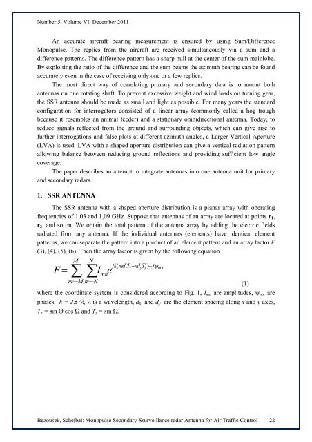
Number 5, Volume VI, December 2011An accurate aircraft bearing measurement is ensured by using Sum/DifferenceMonopulse. The replies from the aircraft are received simultaneously via a sum and adifference patterns. The difference pattern has a sharp null at the center of the sum mainlobe.By exploiting the ratio of the difference and the sum beams the azimuth bearing can be foundaccurately even in the case of receiving only one or a few replies.The most direct way of correlating primary and <strong>secondary</strong> data is to mount bothantennas on one rotating shaft. To prevent excessive weight and wind loads on turning gear,the SSR antenna should be made as small and light as possible. For many years the standardconfiguration for interrogators consisted of a linear array (commonly called a hog troughbecause it resembles an animal feeder) and a stationary omnidirectional antenna. Today, toreduce signals reflected from the ground and surrounding objects, which can give rise tofurther interrogations and false plots at different azimuth angles, a Larger Vertical Aperture(LVA) is used. LVA with a shaped aperture distribution can give a vertical radiation patternallowing balance between reducing ground reflections and providing sufficient low anglecoverage.The paper describes an attempt to integrate antennas into one antenna unit for primaryand <strong>secondary</strong> <strong>radar</strong>s.1. SSR ANTENNAThe SSR antenna with a shaped aperture distribution is a planar array with operatingfrequencies of 1,03 and 1,09 GHz. Suppose that antennas of an array are located at points r 1 ,r 2 , and so on. We obtain the total pattern of the antenna array by adding the electric fieldsradiated from any antenna. If the individual antennas (elements) have identical elementpatterns, we can separate the pattern into a product of an element pattern and an array factor F(3), (4), (5), (6). Then the array factor is given by the following equationM Njk(md xTx+ ndyTy)+ jψmnF = ∑∑Imnem=−M n=−N(1)where the coordinate system is considered according to Fig. 1, I mn are amplitudes, ψ mn arephases, k = 2π /λ, λ is a wavelength, d x and d y are the element spacing along x and y axes,T x = sin Θ cos Ω and T y = sin Ω.Bezoušek, Schejbal: Monopulse Secondary S<strong>surveillance</strong> <strong>radar</strong> Antenna for Air Traffic Control 22


