monopulse secondary surveillance radar ... - Perner's Contacts
monopulse secondary surveillance radar ... - Perner's Contacts
monopulse secondary surveillance radar ... - Perner's Contacts

You also want an ePaper? Increase the reach of your titles
YUMPU automatically turns print PDFs into web optimized ePapers that Google loves.
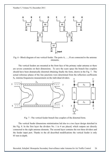
Number 5, Volume VI, December 2011A B C D E F G HV1 V2 V3 V4V5V6V7inputFig. 6 - Block diagram of one vertical feeder. The ports A, …, H are connected to the antennaelements.The vertical feeders are mounted at the front face of the primary <strong>radar</strong> antenna so thereare severe constrains on their dimensions. To save the scare space the branch line couplersshould have been dramatically distorted obtaining finally the form, shown in the Fig. 7. Theactual reference planes of the line junctions were determined from the reflection coefficientsS ii minima frequencies measurement on the individual dividers.323Z B2Z BZ AZ AZ AZ A4Z B14Z 0Z B1Fig. 7 - The vertical feeder branch line couplers of the distorted form.The vertical feeder dimensions minimization led also to a two layer design sketched inthe Fig. 8. In the first layer the dividers No. 1 to 4 are placed, which outputs are directlyconnected to the eight antenna elements. The second layer contains the rest three dividers andthe feeder input port. Thanks to the all described modifications the vertical feeder is only85 mm in depth.Bezoušek, Schejbal: Monopulse Secondary S<strong>surveillance</strong> <strong>radar</strong> Antenna for Air Traffic Control 26