monopulse secondary surveillance radar ... - Perner's Contacts
monopulse secondary surveillance radar ... - Perner's Contacts
monopulse secondary surveillance radar ... - Perner's Contacts

Create successful ePaper yourself
Turn your PDF publications into a flip-book with our unique Google optimized e-Paper software.
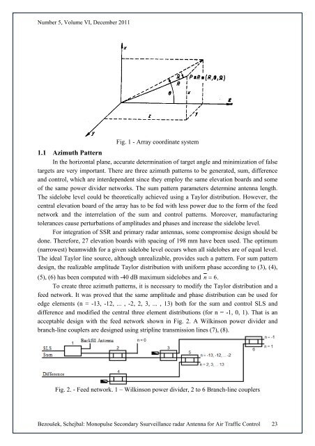
Number 5, Volume VI, December 2011Fig. 1 - Array coordinate system1.1 Azimuth PatternInthe horizontal plane, accurate determinationn of target angle and minimizationn of falsetargets are very important. There are three azimuth patterns to be generated, sum, differenceand control, whichh are interdependent since they employ the same elevation boards and someof the same powerdivider networks. The sum pattern parameters determine antennaa length.The sidelobe level could be theoreticallyachieved using a Taylor distribution. However, thecentral elevation board of the array has to be fed with less power due to the form of the feednetworkand the interrelationn of the sum and control patterns. Moreover, manufacturingtolerances cause perturbationsof amplitudes and phases and increase the sidelobe level.For integration of SSR and primary<strong>radar</strong> antennas, somecompromise design should bedone. Therefore, 27 elevation boards with spacing of 198 mm have been used. The optimum(narrowest) beamwidth for a given sidelobe level occurs when all sidelobes are of equal level.The ideal Taylor line source, although unrealizable,provides such a pattern. For sumpatterndesign, the realizable amplitude Taylor distribution with uniform phase according to (3), (4),(5), (6) has been computed with -40 dB maximum sidelobes andn = 6.Tocreate three azimuth patterns, itis necessary to modifythe Taylor distribution and afeed network. It was proved that the same amplitude and phase distribution can be used foredge elements (n = -13, -12, ... , -2, 2, 3, ... , 13)both for the sum and control SLS anddifference and modified the central threee element distributionss (for n = -1, 0, 1). That is anacceptable design with the feed networkshown inFig. 2. A Wilkinson power divider andbranch-line couplers are designed using stripline transmission lines (7), (8).Fig. 2. - Feed network. 1 – Wilkinson power divider, 2 to6 Branch-line couplersBezoušek, Schejbal: Monopulse Secondary S<strong>surveillance</strong>e <strong>radar</strong> Antenna for Air Traffic Control 23