Nonlinear Cloth Simulation - dgp
Nonlinear Cloth Simulation - dgp
Nonlinear Cloth Simulation - dgp

You also want an ePaper? Increase the reach of your titles
YUMPU automatically turns print PDFs into web optimized ePapers that Google loves.
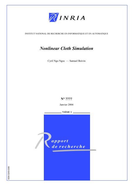
ISSN 0249-6399<br />
INSTITUT NATIONAL DE RECHERCHE EN INFORMATIQUE ET EN AUTOMATIQUE<br />
<strong>Nonlinear</strong> <strong>Cloth</strong> <strong>Simulation</strong><br />
Cyril Ngo Ngoc — Samuel Boivin<br />
N° ????<br />
Janvier 2004<br />
THÈME 3<br />
apport<br />
de recherche
<strong>Nonlinear</strong> <strong>Cloth</strong> <strong>Simulation</strong><br />
Cyril Ngo Ngoc , Samuel Boivin<br />
Thème 3 — Interaction homme-machine,<br />
images, données, connaissances<br />
Projet Alcove<br />
Rapport de recherche n° ???? — Janvier 2004 — 27 pages<br />
Abstract: This research report describes a cloth simulation system including nonlinear behaviors.<br />
Our cloth model simulates the fabric as a complex yarn interlacing structure. This approach allows<br />
us to deal with the yarn scale problem by including the nonlinear interactions happening inside this<br />
structure. This model has three different components: the traction, the bending and the shearing.<br />
We also add new friction terms in order to reproduce the yarn interlacing structure and the nonlinear<br />
properties of a real cloth. Moreover, this representation avoids a detailed 3D geometric model of<br />
yarns which is almost always unusable in computer graphics.<br />
Furthermore, our physical model is based on the Kawabata Evaluation System (KES). It reproduces<br />
the behavior of a cloth using the parameters coming from direct measurements on real<br />
clothes. Therefore we propose an identification procedure to compute all the physical parameters<br />
of our model from the KES curves. Since many textile manufacturers use this KES to design their<br />
fabrics, we are able to accurately simulate their real fabrics in computer graphics using the manufacturer’s<br />
parameters. The simulation of a complete garment made of these fabrics could also be<br />
achieved in a virtual fashion show to visualize its characteristics and/or flaws for example.<br />
Key-words: <strong>Nonlinear</strong> Deformation, <strong>Cloth</strong> <strong>Simulation</strong>, Physically Based Modeling, Parameter<br />
Identification, Hysteresis, Solid Friction, Numerical Computation<br />
Unité de recherche INRIA Futurs<br />
Parc Club Orsay Université, ZAC des Vignes,<br />
4, rue Jacques Monod, 91893 ORSAY Cedex (France)<br />
Téléphone : +33 1 72 92 59 00 — Télécopie : +33 1 72 92 59 ??
<strong>Simulation</strong> de Tissus Non-Linéaires<br />
Résumé : Ce rapport de recherche décrit un système de simulation de tissus intégrant des comportements<br />
non-linéaires. Notre modèle simule le tissu comme une structure complexe de fils entrelacés.<br />
Cette approche permet de prendre en compte le problème de l’échelle du fil en incluant des interactions<br />
non-linéaires à l’intérieur même de la structure. Ce modèle possède en fait trois composantes<br />
différentes: la traction, la flexion et le cisaillement. Nous avons également ajouté de nouveaux<br />
termes de frottement afin de reproduire la structure de fils entrelacés et les propriétés non-linéaires<br />
d’un vrai tissu. Par ailleurs, cette représentation évite une modélisation géométrique 3D détaillée<br />
des fils, pratiquement toujours inutilisable en synthèse d’images.<br />
De plus, notre modèle physique est basé sur le Système d’Evaluation de Kawabata (KES). Il<br />
reproduit le comportement d’un tissu en utilisant les paramètres venant directement de mesures sur<br />
des tissus réels. C’est pourquoi nous proposons une technique d’identification de tous les paramètres<br />
physiques de notre modèle depuis les courbes de Kawabata. Dans la mesure où beaucoup de fabricants<br />
de textiles utilisent le Système d’Evaluation de Kawabata pour concevoir leurs tissus, nous<br />
sommes capables de simuler avec précision leurs tissus réels en synthèse d’images, et en utilisant<br />
les paramètres du fabricant. La simulation d’un vêtement complet conçu de ces tissus pourrait alors<br />
être effectuée dans un défilé de mode virtuel pour visualiser ses caractéristiques et/ou ses défauts par<br />
exemple.<br />
Mots-clés : Déformation non-linéaire, <strong>Simulation</strong> de tissus, Modélisation physique, Identification<br />
de paramètres, Hysteresis, Frottement de solides, Calcul Numérique
<strong>Nonlinear</strong> <strong>Cloth</strong> <strong>Simulation</strong> 3<br />
1 Introduction<br />
1.1 Overview of the problem<br />
Many works have been proposed to simulate clothes in computer graphics [56, 20, 52, 53, 11, 46, 5,<br />
24, 55, 17, 4]. However none of these works are really usable in a textile industrial context. Indeed,<br />
most of manufacturers would like to visualize their model using computer graphics techniques. But<br />
none of the existing physical models for image synthesis are able to take into account the real parameters<br />
that they use to design the fabrics. Many fabric designers use the Kawabata’s Evaluation<br />
System (KES) to get the mechanical properties of their clothes. Actually, a KES is a powerful device<br />
that produces curves depending on the applied force (traction, bending or shearing). These curves<br />
accurately describe the real behavior of a fabric. In this research report, we introduce a new physical<br />
model for cloth simulation including the Kawabata’s parameters coming from KES experiments. A<br />
real fabric always has a nonlinear behavior, and this is characterized by hysteresis (see section 3.1).<br />
Our cloth model includes this nonlinear phenomenon through a new friction model which simulates<br />
the physical contact between yarns without any explicit geometric modeling of fibers. We also<br />
propose a new stable and reliable method for implicit integration handling nonlinear deformations.<br />
1.2 Organization of the research report<br />
The research report is organized as follows. In the next section, we discuss previous work related to<br />
cloth simulation. Section 3 describes the bases and the tools necessary to understand our model. In<br />
particular we present the notion of hysteresis which is mainly responsible for the nonlinear behaviors<br />
of a cloth. We also explain the different existing friction models. Section 4 depicts our cloth model in<br />
details. Each of the three components characterizing our model is explained in details: the traction,<br />
the bending and the shearing. We also show how to integrate our own friction model into these<br />
components. Section 5 gives the description of our implicit integration method. In section 6, we<br />
describe an identification technique to match the real KES curves to the ones produced by our model.<br />
This validates our cloth model. Section 7 shows some computation times and images generated using<br />
our cloth model. The last section brings forward some conclusions and future research directions.<br />
2 Background and Previous Work<br />
Since this research report is concerned with cloth dynamics and particularly internal cloth dynamics,<br />
we do not address collisions or self-collisions. In this research report, we use our own simple<br />
collision model but any advanced model could be used [14].<br />
We distinguish two categories of techniques of cloth models. The first one concerns the pure<br />
textile research area. The second one is about cloth in computer graphics.<br />
RR n° 0123456789
4 Ngo Ngoc & Boivin<br />
2.1 <strong>Cloth</strong> Modeling in Textile Research<br />
Many works have been done in textile research to simulate clothes. Pierce first developed a geometric<br />
and a force-geometry model [44] to describe a plain weave woven fabric. He assumed that the yarns<br />
within the fabric were perfectly flexible and circular in cross section. This model can be applied to a<br />
limited range of problems because it is either based on geometric relations or on a simple mechanical<br />
description. Kemp [38] modified Pierce’s model introducing the yarn flattening. Many other authors<br />
proposed Pierce-like models adding extensions [43, 29, 36, 1, 28].<br />
Strain energy methods simulate the cloth by creating and minimizing equations that define the<br />
energy in a textile structure. These models can be divided into two categories. The first one concerns<br />
the low-level structural models and they are based on the deformation of yarns [31]. The second one<br />
is a high-level structural model using the shell and plate theory [3].<br />
These models from the textile research community allow a better understanding of the problem,<br />
but they use empiric parameters or assumptions that have to be validated. This is a recent area called<br />
parameter identification. We discuss this subject in section 2.3.<br />
2.2 <strong>Cloth</strong> Modeling in Computer Graphics<br />
There is a rich history about cloth simulation in computer graphics. The non-physical approaches<br />
[56, 20] focus on roughly approximations of cloth without any dynamics. Wei [56] first defined a<br />
geometric approach to approximate the folds in a cloth. Coquillart [20] has proposed the free form<br />
deformations to simulate fabrics. These two models have no real physical modeling regarding the<br />
forces and the energy of the deformable object.<br />
On the other hand, physically-based modeling techniques use mechanic models to realistically<br />
simulate a cloth. We propose to split these techniques into two parts: the continuous models [52, 53]<br />
and the discrete models [11, 46, 5, 24, 55, 17, 4] which our contribution belongs to.<br />
2.2.1 Continuous models<br />
Terzopoulos et al. [52, 53] have proposed elasticity-based models to simulate a deformable structure<br />
such as cloth. This model is an approximation of the continuous dynamics that is solved by finite<br />
elements or finite differences. Eischen et al. [27] use a nonlinear shell theory to accurately simulate<br />
cloth. Finite elements methods do not take into account the yarn/fabric structure. They generally<br />
simulate the textile surface without describing the inner mechanic.<br />
2.2.2 Discrete models<br />
Discrete models use mass-spring or particle systems driven by energy functions and forces to depict<br />
a cloth. Our model belongs to this category.<br />
Baraff et al. [5] describes an implicit integration scheme avoiding the stiffness problem. They<br />
have developed a method to constrain the cloth model with a low computation time. This groundbreaking<br />
approach is then used to improve cloth simulation. Volino et al. [55] and Ascher et al.<br />
[4] focus their work on the numerical analysis to enhance the performance and the accuracy of the<br />
INRIA
<strong>Nonlinear</strong> <strong>Cloth</strong> <strong>Simulation</strong> 5<br />
simulation. In order to achieve real-time performance, Desbrun et al. [24] make further approximations<br />
and violate the local preservation of the angular moments. Provot [46] uses explicit integration<br />
and he avoids the stiff problem using weaker springs. Furthermore a post-processing step limiting<br />
the strain rate of stretching is necessary. He thus makes a coarse approximation of the cloth rigidity.<br />
Breen et al. [12, 11] use a set of K.E.S fabric tests to develop specific bending, shearing and<br />
traction models. However these models do not take into account the hysteresis and they are limited<br />
to the static case: only the final state of the cloth is used. Recently, Bridson et al. [13] proposed<br />
a new formulation for a bending model with interesting visual results. Choi et al. [17] reduce the<br />
over-damping due to implicit integration. Unfortunately these works suffer from a linearization of<br />
the cloth dynamics. They also introduced a specific bending energy to reproduce more accurately<br />
folds in cloth. These results are visually spectacular but they have a low physical interpretation. This<br />
signifies that they are unusable in our case.<br />
In their book Breen et al. [30] conclude that developing a new detailed structural model of the<br />
cloth is an important challenge: “from the yarn behavior, together with a weaving or knitting plan,<br />
it should be possible to predict the behavior of finished fabric”. This approach raises several tough<br />
problems especially the internal friction interactions between yarns. Our model actually tries to<br />
solve this problem (see section 4). But a more detailed cloth model is not only required in CAD<br />
systems [42]. It is also a possible answer to the problem adressed by Bhat et al. [6] about choosing<br />
the right parameters of a desired fabric (see next section and section 6).<br />
2.3 Parameter Identification<br />
Having a mechanical model is essential to produce realistic cloth simulations. However, these simulations<br />
are difficult to tune due to the many parameters that must be adjusted to achieve the look of a<br />
particular fabric [6]. Therefore many works have been proposed to identify the parameters of a given<br />
fabric using specific data or input images [12, 11, 16, 39, 33, 19, 35, 26, 6]. However very few of<br />
these papers have validated their techniques on real data [48, 49, 19]. This research report attempts<br />
to solve this problem, identifying the Kawabata’s parameters from the KES data on real fabrics (see<br />
section 6).<br />
In general, people validate their results with a simple visual comparison. Colier et al. [19] use<br />
a finite-element cloth model with measured mechanical properties. They estimate the accuracy of<br />
their simulated draping position using a drapemeter [18]. However the drapemeter is not accurate<br />
enough for a true mechanical validation and for textile industry applications. Louchet et al. [39]<br />
and Joukhadar et al. [33] use an evolutionary algorithm to identify the parameters of a deformable<br />
object.<br />
Chen et al. [16] study the influence of the parameters and highlighted their fundamental role<br />
in cloth simulation. Realff et al. [48, 49] propose a fabric model to simulate the uniaxial tension<br />
(traction). Their approach uses the original fabric geometry and the yarn measured properties from<br />
mechanical experiments to identify and validate the fabric model. The identified parameters are then<br />
compared to the real tensile tests [49]. However, even if this approach shows accurate results, it only<br />
deals with the traction. No bending or shearing is performed.<br />
RR n° 0123456789
6 Ngo Ngoc & Boivin<br />
Breen et al. [12, 11] compute energy functions from Kawabata’s experiments on fabrics. They<br />
identify the parameters only from a part of the Kawabata’s curve (no hysteresis) using a polynomial<br />
approximation and a linear fitting. This technique results in a set of non-physical parameters.<br />
Eberhardt et al. [26] follow the previous approach but they used a different method. They also<br />
extend the technique to the dynamic case and identify the whole Kawabata’s curve (hysteresis). They<br />
used the KES experimental data and they fit the curve applying successive piecewise linear functions.<br />
Since they have developed an empirical and linear approach, the authors roughly approximate the<br />
hysteresis.<br />
Recently, Bhat et al. [6] presented a promising algorithm to identify the parameters from a set of<br />
real images of a cloth simulation. The major advantage of this technique is to allow the estimation<br />
of the parameters of Baraff’s model [5] from videos. However, it is not suitable for textile industry<br />
applications that require a much more accurate cloth model to simulate real fabrics. An extension of<br />
Bhat et al.’s method to a nonlinear cloth model simulating hysteresis would be extremely useful.<br />
3 <strong>Cloth</strong> Physics<br />
In this section we describe the two important concepts that are required to understand our model:<br />
the yarn interlacing structure and the friction models.<br />
3.1 The hysteresis<br />
When deformation of a fabric occurs (for small strains like drape), traction, bending as well as<br />
shearing phenomena have to be simulated. They are characterized by a nonlinear behavior and<br />
especially hysteresis. The hysteresis is difficult to handle because it is a subtle physical phenomenon.<br />
However, it is essential to a realistic cloth simulator using computer graphics for textile industrial<br />
applications. The hysteresis corresponds to a delay in the evolution of a physical system that tends to<br />
preserve its initial state. In many cases, this is commonly considered as a memory form effect. The<br />
fact that the fabric is a yarn interlacing structure creates the illusion that the structure and especially<br />
the geometry of the fabric are generating this behavior. However, the study of yarn clearly shows<br />
that the yarn and the assemblage of fibers are responsible of these non-linearities. The geometry of<br />
the fabric does not create any major nonlinear phenomenon. These fibers are maintained together by<br />
a twisting process better known as torsion. Their organization makes them slightly move inside the<br />
assemblage, thus creating an internal friction effect and hysteresis.<br />
3.2 Internal Friction<br />
Friction forces play a major role in everyday life. Without it, we would not be able to walk or to hold<br />
our pants. Friction occurs in every mechanical system especially when there is a physical interaction<br />
between two surfaces brought into contact. A wide range of physical phenomena cause friction. This<br />
includes elastic traction, plastic deformations, wave phenomena, etc.. The friction is the tangential<br />
reaction force between two surfaces brought into contact. Actually these reaction forces are the<br />
INRIA
<strong>Nonlinear</strong> <strong>Cloth</strong> <strong>Simulation</strong> 7<br />
combination of many different mechanisms. They depend on the contact geometry and topology, the<br />
materials of the surface, the displacement speed, the relative velocity and the presence of lubricant.<br />
Friction Force<br />
Fc<br />
Friction Force<br />
-Fc<br />
Velocity<br />
Friction Force<br />
Fc<br />
-Fc<br />
Coulomb Coulomb + viscosity<br />
Fc<br />
-Fc<br />
Velocity<br />
Friction Force<br />
Fc<br />
-Fc<br />
Velocity<br />
Velocity<br />
Coulomb + viscosity + stiction Coulomb + viscosity + Stribeck<br />
Figure 1: Classical Friction Models<br />
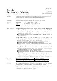
Most friction models are based on Leonardo da Vinci’s laws of friction. The physicist Amonton<br />
made simlilar studies and he defined two laws: friction is directly proportional to the applied<br />
load, and friction is independent of the obvious area of contact [2]. Coulomb published one of the<br />
most famous and comprehensive studies about friction [21]. Lately Karnopp [34] and Stribeck [50]<br />
improved the Coulomb’s model in order to take into account the stiction and the Stribeck effect<br />
(see figure 1). These laws provide useful estimates and qualitative predictions for a wide range of<br />
behaviors associated with friction. They are looked upon as static models because friction is not<br />
considered as a dynamic phenomenon. This feature presents fundamental and practical drawbacks<br />
especially with low velocity. More advanced models may be required in specialized area like cloth<br />
modeling.<br />
As described in section 3.1, a yarn is a fibrous assemblage. When a deformation occurs, the<br />
contact between two fibers or between the weft and the warp produce friction. Therefore we consider<br />
that hysteresis happens during the fabric deformation. But the observation of this effect shows three<br />
specific characteristics especially when the cloth dynamic is in its transition phase (acceleration for<br />
example):<br />
• Pre-sliding effect which corresponds to a spring-like response in order to characterize limited<br />
friction start,<br />
• Static friction effect which is the friction intensity when velocity is null,<br />
RR n° 0123456789
8 Ngo Ngoc & Boivin<br />
• Stribeck effect which is a diminution of the friction force for small velocity. This is caused by<br />
a transition between lubricated friction and partial lubricated friction [50].<br />
Classical friction models are not able to reproduce these characteristics because the friction force<br />
does not depend on the velocity. The friction is not considered as a dynamic phenomenon and<br />
consequently it does not model a dynamic system. Creating a general friction model using basic<br />
physical laws is not powerful enough. Approximated models exist for certain configurations. But<br />
we rather look for a general model for cloth simulation, including the friction phenomena. This<br />
also means that we are not interested in a microscopic friction model which would increase the<br />
computational cost. Experiments have been performed under ideal conditions to develop a new<br />
class of friction models focusing on the dynamic properties. These models really fit experimental<br />
observations regarding friction[47, 22]. Classical models do not. Another advantage of this model is<br />
its ability to depict the three previous physical characteristics (pre-sliding, static friction and stribeck<br />
effects) in textile modeling. It also depends on identifiable physical parameters. Therefore we use<br />
these works to develop our internal friction model for cloth simulation (see section 4.2).<br />
4 <strong>Cloth</strong> Model<br />
4.1 General structure<br />
The main idea of our model is to simulate the nonlinear properties of the cloth using internal friction<br />
terms. Actually we use three fundamental components to build our model: the shearing, the bending<br />
and the traction (see figure 2). Every component integrates a friction term in order to preserve<br />
hysteresis. The moments and the forces of each component are described in the section 4.3.<br />
Close view of a cloth<br />
Figure 2: Our cloth model.<br />
p(i,j)<br />
Traction<br />
Connector (TC)<br />
Bending<br />
Connector (BC)<br />
Shearing<br />
Connector (SC)<br />
Corresponding particle model<br />
Our cloth model is based on a mesoscopic analysis of cloth. It is approximated by a quadrilateral<br />
mesh of interconnected particles p(i, j) [10], because it can handle the exact geometry of cloth (e.g.<br />
crossing warp and weft yarns). This representation simulates fabrics by modeling the low level<br />
structure of the material and the anisotropic behavior due to different warp and weft properties. The<br />
Joukhadar connector system [32] is used to depict the connections between particles, as shown in<br />
INRIA
<strong>Nonlinear</strong> <strong>Cloth</strong> <strong>Simulation</strong> 9<br />
figure 2. However the three types of connectors (bending(BC), traction(TC), shearing (SC)) have<br />
different mathematical and physical formulations in our case (see section 4.3).<br />
4.2 Internal friction model<br />
Our model of internal friction is based on a generalization of the classical Coulomb’s model. We<br />
show here how to include this friction into the three components of our model.<br />
Shear Moment (gf cm -1 )<br />
40<br />
30<br />
20<br />
10<br />
0<br />
-10<br />
-20<br />
-30<br />
-40<br />
-8 -6 -4 -2 0 2 4<br />
Shear Angle (°)<br />
6 8<br />
-<br />
20<br />
10<br />
0<br />
-10 =<br />
Shear Moment (gf cm -1 )<br />
40<br />
30<br />
-20<br />
-30<br />
-40<br />
-8 -6 -4 -2 0 2 4<br />
Shear Angle (°)<br />
6 8<br />
Shear Moment (gf cm -1 )<br />
40<br />
30<br />
20<br />
10<br />
0<br />
-10<br />
-20<br />
-30<br />
-40<br />
-8 -6 -4 -2 0 2 4<br />
Shear Angle (°)<br />
6 8<br />
Deformation moment Main rigidity component Internal friction<br />
Figure 3: Friction Extraction (during shearing)<br />
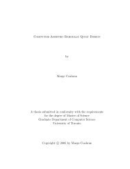
First of all, we apply the KES on different fabric samples using three different deformations<br />
(bending, traction and shearing). We now obtain a Kawabata’s curve depicting the general shape<br />
of the internal friction. For traction, it is a function of force and relative elongation. For bending<br />
and shearing, this curve is a function of moment and either deformation curvature (bending) or<br />
deformation angle (shearing). Then we compute the main rigidity component corresponding to the<br />
main slope of these curves. Finally, we subtract this main rigidity component to the deformation<br />
moment (bending and shearing) or the force (traction) to estimate the internal friction (see figure 3)<br />
of the cloth.<br />
We simulate the internal friction applying an extended version of the Dahl’s model [23]. It was<br />
originally designed for control systems with friction. It is a simple and efficient model that has been<br />
developed from experimental observations about friction in servomotor systems with ball bearings.<br />
Using the stress-strain curve in classical dynamics (see left figure 4), Dahl proposed a differential<br />
equation to simulate the friction force from the displacement:<br />
where:<br />
RR n° 0123456789<br />
dF<br />
dx<br />
F<br />
= σ(1 − sgn(v)) α<br />
σ is the stiffness coefficient,<br />
Fc is the the Coulomb’s friction force,<br />
v is the displacement speed,<br />
α is a parameter that controls the shape of the stress-strain curve.<br />
α = 1 is used except for plastic materials where α > 1.<br />
Fc
10 Ngo Ngoc & Boivin<br />
To get a time friction function the model is simply rewritten as follow :<br />
dF<br />
dt<br />
dF dx F<br />
= = σ(1 − sgn(v))<br />
dx dt Fc<br />
α v (1)<br />
This model is a generalization of ordinary Coulomb’s friction with the possibility to reproduce<br />
hysteresis, pre-sliding and zero-slip displacement. It also only depends on the displacement and the<br />
sign of the velocity.<br />
The shape of the friction curve presented in figure 4 shows the phenomena described in the<br />
previous sections (pre-sliding, Coulomb’s friction and Stribeck effect).The Dahl’s model might be<br />
used as a first approximation to capture the friction behavior. However it does not take into account<br />
the stiction and the Stribeck effect which is a rate dependent phenomenon. Therefore we propose to<br />
use an extension of the Dahl’s model, as the one developed by Bliman and Sorine[8, 7]. This model<br />
is also built on the Rabinowicz’s experimental observations and the theory of the hysteresis operator.<br />
Bliman and Sorine defined the space variable s : s = � t<br />
o |v(τ)|dτ<br />
Using this space variable, they stress that friction is a function of the path only. It does not<br />
depend on how fast the system moves along the path. The models are then defined by a linear state<br />
model of the variable s:<br />
dxs<br />
ds = Axs + Bvs<br />
F = Cxs<br />
where vs is sgn(v), the sign of v.<br />
This model has different complexities according to its order. The first order model is given by:<br />
A = −1/ε f, B = f1/ε f, C = 1<br />
where ε f is the displacement giving the pre-sliding slope σ.<br />
It can also be written as:<br />
dF dF ds<br />
=<br />
dt ds dt = f1/ε f (1 − F<br />
sgn(v)) v<br />
Fc<br />
Actually, this first order model corresponds to the Dahl’s Model (1) with f1 = Fc, σ = f1/ε f<br />
and α = 1. Unfortunately, it still does not handle the stiction and the Stribeck effect. This can be<br />
achieved with the second order model:<br />
� �<br />
−1/(ηε<br />
A =<br />
f) 0<br />
� 0 � −1/ε f<br />
f1/(ηε f )<br />
B =<br />
− f2/ε f<br />
C = � 1 1 �<br />
(2)<br />
where f 1 − f 2 corresponds to the kinetic friction reached exponentially as s → ∞ [9]. This model<br />
can be viewed as a parallel connection of a fast and a slow Dahl’s model. The fast model has higher<br />
Coulomb’s friction than the slow model. The force from the slow model is subtracted from the fast<br />
model, which results in a stiction peak. Both the first and second order models can be shown to be<br />
dissipative. Bliman and Sorine also show that, as ε f goes to zero, the first order model behaves as<br />
INRIA
<strong>Nonlinear</strong> <strong>Cloth</strong> <strong>Simulation</strong> 11<br />
��� ���ε� ���<br />
.<br />
¡σ §£¨©��¡���¦¤ ¡ ¢£¡¤£¥¦<br />
�<br />
.<br />
Friction<br />
Stiction<br />
peak<br />
0<br />
-F�<br />
Pre-sliding<br />
σ<br />
Stribeck Effect<br />
Fc=f1-f2<br />
0 Displacement<br />
Dahl’s Dynamic Model Enhanced Dynamic Model<br />
(Bliman-Sorinne)<br />
Figure 4: <strong>Cloth</strong> Internal Friction<br />
a classical Coulomb’s friction model. The second order model behaves as a classical model with<br />
Coulomb’s friction and stiction.<br />
We now have an internal friction model capable of simulating nonlinear forces during the fabric<br />
deformation. In the next section, we explain how to integrate this friction into each of the three<br />
components of our cloth model.<br />
4.3 Moments and Forces<br />
As described in the section 4.2 we characterize the cloth hysteresis by subtracting an elastic force.<br />
The traction, the bending and the shearing have an elastic force coupled with other forces. We can<br />
write the following formulation for the internal force F:<br />
F = FTC + FBC + FSC<br />
= ∑ Ftract p(i, j) + Fbend p(i, j) + Fshear p(i, j)<br />
i, j<br />
where FTC, FBC and FSC are the traction, the bending and the shearing forces respectively.<br />
4.3.1 Traction<br />
Our model has been made possible by many scientific contributions about the yarn and the fabric<br />
traction [54, 15, 49]. We have also performed several traction tests on different fabric samples to<br />
capture the general behavior of this force. From these experiments we extract a general shape split<br />
into four different parts (see left figure 6):<br />
• The first part is the priming zone of yarns. The fibers are partially organized as the initial state<br />
(see right figure 6). When traction occurs, theses fibers receive longitudinal efforts aligning<br />
RR n° 0123456789
12 Ngo Ngoc & Boivin<br />
zone 1<br />
zone 2<br />
p 1<br />
x<br />
z<br />
F tract p1<br />
Figure 5: Traction Connector<br />
F tract p2<br />
them in the same direction. This effect leads to a lower traction resistance. We model it by<br />
a modified rigidity using a distribution function. This function characterizes the progressive<br />
alignment of the fibers. The internal friction caused by the fiber interactions is also affected<br />
the progressive alignment. Moreover, the yarn is blocked in a fabric structure. It cannot be<br />
longitudinally compressed. We use a geometric constraint to avoid any compression, but Choi<br />
et al.’s method [17] could also be used.<br />
• The second part is the linear elastic response of the fabric. It includes a stiffness coefficient kt<br />
known as the linear rigidity, and a friction term.<br />
• The third part corresponds to the fabric damaging. In the case of cloth draping, this can be<br />
neglected.<br />
• The fourth part is the hysteresis. It takes into account the friction between fibers during an<br />
elastic elongation.<br />
F (N)<br />
F 1<br />
part 1<br />
ε 1<br />
part 2 part 3<br />
k t<br />
ε c<br />
ε 1'<br />
part 4<br />
ε (%)<br />
ε 1<br />
F<br />
p 2<br />
Initial State Zone 1 Zone 2<br />
Fabric traction shape Fiber deformation during traction.<br />
Figure 6: Description of fabric and fiber behaviors during a traction process.<br />
y<br />
F<br />
INRIA
<strong>Nonlinear</strong> <strong>Cloth</strong> <strong>Simulation</strong> 13<br />
We propose the following model for the Traction Connector (TC) which links two particles (p1<br />
and p2) (see figure 2c):<br />
�Ftract p1 =<br />
⎧<br />
if |�Ftract p1 | ≤ F1<br />
⎪⎨<br />
��<br />
1 −<br />
⎪⎩<br />
F1<br />
�<br />
ε + ktεc<br />
2F1<br />
��<br />
− εc kt kt ε εc + Ftract f r (vs)<br />
�<br />
�kp1<br />
else<br />
kt (ε − εc)+F1 + Ftract f r (vs)�kp1<br />
(3)<br />
where:<br />
ε is the relative elongation between the two particles,<br />
εc = (ε1 or ε ′ 1 ) is the relative elongation defined by the deformation<br />
of fibers during traction (with initial value ε1),<br />
Ftract f r is a friction force (N) defined by a first order<br />
Bliman-Sorine’s model (see eq. 1) with:<br />
= Cxs,<br />
Fctract<br />
ε f rtract<br />
Ftract f r<br />
vs = sign(˙ε(t)) s(t) = � t<br />
0 |˙ε(τ)|dτ,<br />
A = −1/ε f rtract , B = Fctract /ε f rtract<br />
, C = 1.<br />
is the Coulomb’s friction force (N),<br />
is the relative elongation defining the pre-sliding,<br />
˙ε is the relative elongation speed,<br />
kt<br />
is the linear rigidity for the relative elongation,<br />
F1<br />
is the force (N) defining a change between zone 1<br />
and zone 2 (see figure 6),<br />
�kp1<br />
4.3.2 Bending<br />
RR n° 0123456789<br />
¡¢£¤¥<br />
is a unit vector defined as�kp1<br />
F bend p1<br />
= �p2−�p1<br />
|�p2−�p1| .<br />
© ¦�<br />
� ¦¨ ¦§<br />
Figure 7: Bending Connector �<br />
F bend p3<br />
.<br />
Fbend p2 �
14 Ngo Ngoc & Boivin<br />
The Bending Connector (BC) represents the constraint applied to the three particles p1, p2 andp3<br />
(see figure 2b). The force applied by this connector to the particles p1 and p2 is given by the<br />
following equation:<br />
�Fbend p1 = kb(K − K0)+Mf r (vs) bend �Fp1<br />
(4)<br />
|�p3 − �p1|<br />
where:<br />
K is the curvature (m−1 ) of the three particles computed<br />
from Breen’s equation [10],<br />
K0 is the residual curvature (m−1 ) for plastic<br />
deformation (for example a permanent fold) ,<br />
kb is the flexural rigidity, representing linear elastic<br />
relation between curvature and bending moment (N.m2 ),<br />
�Fp1 is the unit vector perpendicular to the direction −−→ p1p3,<br />
Mf r is the friction moment for bending (N · m bend<br />
−1 ) due to fiber<br />
collisions.<br />
The friction moment is given by a Bliman-Sorine’s second order model with:<br />
Mf r = Cxs<br />
bend<br />
The space variable is now:<br />
where ˙K is the curvature speed.<br />
� t<br />
vs = sign( ˙K(t)) s(t) = | ˙K(τ)|dτ<br />
0<br />
If we do not need to simulate the Stribeck effect, we can use a first order model with:<br />
A = −1/Kf r , B = Mc /Kf bend bend r , C = 1<br />
bend<br />
where:<br />
Mc is the friction moment (N · m bend<br />
−1 ), e.g. the Coulomb’s friction<br />
is the curvature representing the pre-sliding effect (m−1 ).<br />
Kf r bend<br />
The force �Fbending p3 applied to the particle p3 is the result of the action/reaction principle. It is<br />
simply given by:<br />
�Fbending p3 = −(�Fbending p1 +�Fbending p2 )<br />
.<br />
4.3.3 Shearing<br />
The cloth shearing is very different from traction and bending. The shearing is caused by the deformation<br />
of the cloth structure. The yarn deformation does not generate any shearing. Therefore it<br />
only depends on the cloth geometry and yarn friction.<br />
This phenomenon leads into the following conclusions:<br />
• The small deformations produced by shearing are mainly due to frictions between warp and<br />
weft yarns.<br />
INRIA
<strong>Nonlinear</strong> <strong>Cloth</strong> <strong>Simulation</strong> 15<br />
¢<br />
¤ ¥<br />
θ ¦ § £ ¡<br />
F shearing p1<br />
Figure 8: Shearing Connector<br />
F shearing p3<br />
F shearing p1<br />
• For high stress, the shearing is caused by the yarn jamming. Therefore we have to constraint<br />
the cloth geometry with a maximum shearing angle. In practice, the bending effect occurs<br />
before this angle is reached. this is due to the important rigidity of a cloth.<br />
Analyzing the data of the Kawabata’s curves (see figure 10), we propose a shearing model for<br />
small deformations based on a second order Bliman-Sorine’s model:<br />
Mshear = ks(θ − θ0)+Mf r shear<br />
Mf r shear<br />
with vs = sign( ˙θ(t)) s(t) = � t<br />
0 | ˙θ(τ)|dτ.<br />
= Cxs<br />
If the Stribeck effect is not required, a first order model with the following parameters is enough (see<br />
equation 2):<br />
A = −1/θ f, B = Mc shear /θ f r shear , C = 1<br />
where:<br />
ks<br />
θ0<br />
Mcshear θ f rshear is the shearing rigidity N · m−1 · rad−1 corresponding to<br />
the linear elastic response,<br />
is the initial angle between particles (usually π 2 ),<br />
is the moment (N · m−1 ) for the Coulomb’s friction,<br />
is the angle characterizing the pre-sliding shearing<br />
friction (see 4.2).<br />
The force applied to a non-central particle (for example p1) for a shearing connector (see figure 2a)<br />
is :<br />
�Fshear p1 = ks(θ − θ0)+Mf r (vs)<br />
shear �kp1<br />
|�p3 − �p1|<br />
(5)<br />
where�kp1 =�n ∧�j.<br />
RR n° 0123456789
16 Ngo Ngoc & Boivin<br />
To respect the action/reaction principle, the force applied on p3 is the opposite sum of �Fshear p1 +<br />
, as in the bending case.<br />
�Fshear p2<br />
5 Numerical Integration<br />
The acceleration ¨xi, j of the particle p(i, j) combines the internal forces with the external forces; It<br />
can be written as ¨xi, j = Fi, j/mi, j, where mi, j is the particle mass. The equations of motion lead to the<br />
state equation:<br />
where:<br />
�<br />
d x<br />
dt v<br />
� �<br />
=<br />
v<br />
M −1 F(x,v)<br />
x is the vector containing the particle position<br />
v is the particle velocity.<br />
To solve these equations, a reliable integration method is needed. Implicit methods are a reference<br />
choice by many authors [5, 51, 53]). [5] use the backward Euler method :<br />
�<br />
1 xt+1 − xt Δt vt+1 − vt � �<br />
v<br />
=<br />
t+1<br />
M−1F t+1<br />
�<br />
(6)<br />
In order to reduce the computational cost, they simplify the solution by a first order linear approximation.<br />
The system is solved at each time step with a modified conjugate gradient (CG). Many<br />
authors also have extended this approach[24, 41, 17]. [25] have proposed to mix the implicit scheme<br />
with an explicit scheme.<br />
The methods simulating cloth models usually require the computation of the Jacobian of the<br />
function F, or specific computations (CG) which need positive symmetric matrices. Consequently<br />
these algorithms are slow or they only approximate the dynamics of the cloth. Instead, we prefer to<br />
use Broyden’s method [37] which solves nonlinear systems with a more efficient computation time.<br />
Using the Euler’s backward method (see eq. 6), we have to solve a nonlinear system φ(x) = 0.<br />
Broyden’s method avoids the evaluation of the Jacobian and the linearization of the equations. This<br />
scheme is a quasi Newton’s method, but the Jacobian is incrementally approximated. During one<br />
iteration of the Broyden’s method, we only perform one evaluation of the function φ. This is faster<br />
than any Newton-like methods. This advantage increases with the size of the equation system.<br />
6 Parameter Identification<br />
Our cloth model is able to simulate nonlinear clothes from real data. It may require up to 32 parameters<br />
(16 for the warp and 16 for the weft) in the most complicated case. However, many clothes can<br />
be simulated using 12 parameters if there is no noticeable difference between warp and weft yarns.<br />
�<br />
INRIA
<strong>Nonlinear</strong> <strong>Cloth</strong> <strong>Simulation</strong> 17<br />
Traction-shearing Module Bending Module<br />
Figure 9: Kawabata Evaluation System (KES)<br />
This is still complex enough to make almost impossible any manual estimation of these parameters.<br />
Therefore we propose here an automatic procedure to compute all of them from experiments<br />
characterizing a cloth behavior.<br />
The Kawabata Evaluation System (see figure 9) evaluates traction, shearing and pure bending<br />
behaviors of a fabric. It also provides dynamic measurements. All the parameters of our cloth model<br />
are computable from the KES curves (see figure 10).<br />
Using the KES data, we define a χ 2 merit function of M unknown parameters. We then determine<br />
the best-fit parameters by minimization this function (see tables 1,2 and 3). Usual methods<br />
are inappropriate because of the nonlinear characteristics. We choose the nonlinear least square algorithm<br />
based on the Levenberg-Marquardt method [40]. This method works very well in practice<br />
and has become the standard of nonlinear least-square routines [45]. In our case χ 2 is the quadratic<br />
normal distance between the KES data and the outputs of our three sub-models TC, BC and SC<br />
defined in equation 3, 4 and 5 respectively.<br />
The initial parameters values are directly estimated from the curves. For the traction connector,<br />
the rigidity constant is evaluated by the general shape of the curve. The priming zone parameters<br />
are computed using the slope change of the traction curve. Finally, the friction parameters are given<br />
by the extraction procedure described in section 4.2. We apply the same evaluation process for the<br />
bending and shearing connectors, except that we do not have any priming zone term to approximate.<br />
RR n° 0123456789
18 Ngo Ngoc & Boivin<br />
These initial values are close to the final identified parameters. Therefore the minimization of χ 2 is<br />
instantaneous.<br />
Traction Connector (TC)<br />
Physical Properties Parameters (M) General Shape<br />
Linear<br />
Rigidity<br />
kt<br />
Priming Zone<br />
F1, ε1,<br />
Coulomb<br />
Friction<br />
ε ′ 1<br />
Fctract ,<br />
ε f rtract<br />
Table 1: Traction parameters to identify. There is no Stribeck effect for a traction connector. The<br />
identification procedure may require up to 12 parameters if the cloth has anisotropic properties (warp<br />
and weft yarns have different behaviors).<br />
Shearing Connector (SC)<br />
Physical Properties Parameters (M) General Shape<br />
Linear<br />
Rigidity<br />
ks<br />
Coulomb<br />
Mc1 , shear<br />
Friction<br />
Stribeck<br />
Effect<br />
θ f r1 shear<br />
Mc2 shear ,<br />
θ f r2 shear<br />
Table 2: Shearing parameters to identify. If there is no hysteresis the number of parameters is<br />
reduced from 5 to 3. An anisotropic cloth doubles all the parameters up to a maximum of 10.<br />
As an example, we identified the fabric parameters for an acrylic twill weave fabric. The Kawabata’s<br />
curves do not present any Stribeck effect so we could use for every friction model a first order<br />
model (e.g. Dahl Model). Furthermore, we identify the parameters for the warp and weft direction<br />
as we have an anisotropic behavior.<br />
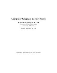
Figure 10 shows the identified models and their accuracy. While identifying the unknown parameters,<br />
we obtained a satisfactory 2%. This error is caused by the high sensitivity of the Kawabata<br />
Evaluation System and the nonhomogeneous nature of the fabric material. Furthermore, it is not<br />
significant as for different cloth material (e.g. silk, coton, wool) traction, shearing and bending<br />
behaviors are varying much more than 2%.<br />
INRIA
<strong>Nonlinear</strong> <strong>Cloth</strong> <strong>Simulation</strong> 19<br />
Bending Connector (BC)<br />
Physical Properties Parameters (M) General Shape<br />
Linear<br />
Rigidity<br />
kb<br />
Coulomb<br />
Mc1 , bend<br />
Friction<br />
Stribeck<br />
Effect<br />
Kf r1 bend<br />
Mc2 bend ,<br />
Kf r2 bend<br />
Table 3: Shearing parameters to identify. As for bending, if there is no hysteresis the number of<br />
parameters is reduced from 5 to 3. An anisotropic cloth doubles all the parameters up to a maximum<br />
of 10.<br />
7 Results and Applications<br />
We have performed several cloth simulations using the parameters computed from the KES curves<br />
of section 6. Table 4 summarizes the performance of our algorithm on an Intel Pentium 4-2Ghz.<br />
number of particles CPU sec/frame time step Δt<br />
400 0.115 0.001<br />
2500 1.321 0.001<br />
4900 6.302 0.001<br />
Table 4: Computation times for nonlinear cloth simulation<br />
The indicated CPU times correspond to the full time required to compute one frame: evaluation<br />
of forces, Broyden’s solving method and collisions. The choice Δt = 1e −3 s is driven by the need<br />
of accurate calculations. A higher time step would make the implicit method create too much artificial<br />
damping for realistic cloth simulation. Moreover, in our case the computational cost is highly<br />
influenced by the parameter values, especially the mass and the rigidity. Indeed, in practice, using<br />
parameters computed from real data generate very strong forces leading to important simulation<br />
computational costs.<br />
One immediate application of our work concerns textile design. None of the existing works in<br />
Computer Graphics are usable in the textile industry because they require too many assumptions<br />
or approximations or they have not been validated on real fabrics using real industrial data (KES<br />
for example). Indeed, the textile industry often uses the KES to get the mechanical properties of<br />
the fabrics that they design. However, they are not able to put any of the Kawabata’s parameters<br />
in a physical model to visualize the fabric or the cloth in computer graphics. Being able to display<br />
clothes in image synthesis from accurate KES data coming is an excellent way for textile industrials<br />
RR n° 0123456789
20 Ngo Ngoc & Boivin<br />
Bending Moment Nm −1<br />
Shear Moment Nm −1<br />
Traction Force N<br />
1<br />
0.8<br />
0.6<br />
0.4<br />
0.2<br />
0<br />
−0.2<br />
−0.4<br />
−0.6<br />
−0.8<br />
KES data<br />
model<br />
−1<br />
−3 −2 −1 0 1<br />
Bending Curvature 10E<br />
2 3<br />
−2 m −1<br />
−40<br />
−8 −6 −4 −2 0 2 4 6 8<br />
Shear Angle °<br />
5<br />
4<br />
3<br />
2<br />
1<br />
0<br />
40<br />
30<br />
20<br />
10<br />
0<br />
−10<br />
−20<br />
−30<br />
KES data<br />
model<br />
KES data<br />
model<br />
−1<br />
0 0.5 1 1.5 2 2.5 3<br />
Relative Elongation %<br />
Bending Moment Nm −1<br />
Shear Moment Nm −1<br />
Traction Force N<br />
0.6<br />
0.4<br />
0.2<br />
0<br />
−0.2<br />
−0.4<br />
−0.6<br />
KES data<br />
model<br />
−0.8<br />
−3 −2 −1 0 1<br />
Bending Curvature 10E<br />
2 3<br />
−2 m −1<br />
40<br />
30<br />
20<br />
10<br />
0<br />
−10<br />
−20<br />
−30<br />
KES data<br />
model<br />
−40<br />
−8 −6 −4 −2 0 2 4 6 8<br />
Shear Angle °<br />
5<br />
4<br />
3<br />
2<br />
1<br />
0<br />
KES data<br />
model<br />
−1<br />
0 0.5 1 1.5 2 2.5 3<br />
Relative Elongation %<br />
Figure 10: Parameter identification results on the KES curves. The left and right columns respectively<br />
correspond to the warp and weft. The blue curves represent the real data coming from KES<br />
experiments. Using the initialization values we compute a set of parameters for our model. We are<br />
then able to produce a new KES curve. The final parameters of our cloth model are obtained by<br />
minimizing the error between this curve and the original blue curve. The red curve is generated<br />
using the final solution (320 iterations were needed). The remaining error (∼ 2%)is due to the high<br />
sensitivity of the Kawabata Evaluation System and the nonhomogeneous nature of the fabric.<br />
INRIA
<strong>Nonlinear</strong> <strong>Cloth</strong> <strong>Simulation</strong> 21<br />
to examine the properties and flaws of their fabrics. This could lead to more realistic virtual fashion<br />
shows because none of our physical parameters are empirically determined.<br />
8 Conclusion and Future Work<br />
We have proposed a simple and accurate physical model to simulate non-linearities and hysteresis<br />
in cloth modeling. It is a particle system driven by force functions and identifiable parameters based<br />
on the Kawabata Evaluation System (KES). It includes an internal friction model to simulate the<br />
organization of yarns inside a fabric without using any complex geometric model. This friction term<br />
is integrated into the three components of our cloth model: the traction, the bending and the shearing.<br />
To solve the inherent equations, we use a rapid integration technique that has the advantages of<br />
standard implicit methods. Efficient nonlinear solving is thus possible. This leads to accurately<br />
simulate the cloth behavior without any approximations.<br />
This physical model is only one step to achieve realistic cloth simulation. Indeed, we would like<br />
now to focus on parameter identification especially from video data. We believe that capturing the<br />
cloth behavior and the Kawabata’s parameters from image sequences is a tough but very promising<br />
challenge.<br />
Many other enhancements are possible to make our cloth model much more powerful. For<br />
example, when a cloth is too much stretched it does not always return to its initial state. The elasticity<br />
does not act anymore and the fabric is damaged. We have already added a damaging term to our<br />
model. However many further tests are required for its validation.<br />
Contents<br />
1 Introduction 3<br />
1.1 Overview of the problem . . . . . . . . . . . . . . . . . . . . . . . . . . . . . . . . 3<br />
1.2 Organization of the research report . . . . . . . . . . . . . . . . . . . . . . . . . . . 3<br />
2 Background and Previous Work 3<br />
2.1 <strong>Cloth</strong> Modeling in Textile Research . . . . . . . . . . . . . . . . . . . . . . . . . . 4<br />
2.2 <strong>Cloth</strong> Modeling in Computer Graphics . . . . . . . . . . . . . . . . . . . . . . . . . 4<br />
2.2.1 Continuous models . . . . . . . . . . . . . . . . . . . . . . . . . . . . . . . 4<br />
2.2.2 Discrete models . . . . . . . . . . . . . . . . . . . . . . . . . . . . . . . . . 4<br />
2.3 Parameter Identification . . . . . . . . . . . . . . . . . . . . . . . . . . . . . . . . . 5<br />
3 <strong>Cloth</strong> Physics 6<br />
3.1 The hysteresis . . . . . . . . . . . . . . . . . . . . . . . . . . . . . . . . . . . . . . 6<br />
3.2 Internal Friction . . . . . . . . . . . . . . . . . . . . . . . . . . . . . . . . . . . . . 6<br />
4 <strong>Cloth</strong> Model 8<br />
4.1 General structure . . . . . . . . . . . . . . . . . . . . . . . . . . . . . . . . . . . . 8<br />
4.2 Internal friction model . . . . . . . . . . . . . . . . . . . . . . . . . . . . . . . . . 9<br />
RR n° 0123456789
22 Ngo Ngoc & Boivin<br />
Figure 11: <strong>Simulation</strong> of clothes using our technique. Since hysteresis is a very subtle effect it is<br />
not possible to display any images having this characteristic. However, these results show that our<br />
physical model is able to produce synthetic images directly using the KES curves. Indeed, these<br />
images have been generated using the KES curves of figures 10.<br />
INRIA
<strong>Nonlinear</strong> <strong>Cloth</strong> <strong>Simulation</strong> 23<br />
4.3 Moments and Forces . . . . . . . . . . . . . . . . . . . . . . . . . . . . . . . . . . 11<br />
4.3.1 Traction . . . . . . . . . . . . . . . . . . . . . . . . . . . . . . . . . . . . . 11<br />
4.3.2 Bending . . . . . . . . . . . . . . . . . . . . . . . . . . . . . . . . . . . . . 13<br />
4.3.3 Shearing . . . . . . . . . . . . . . . . . . . . . . . . . . . . . . . . . . . . 14<br />
5 Numerical Integration 16<br />
6 Parameter Identification 16<br />
7 Results and Applications 19<br />
8 Conclusion and Future Work 21<br />
References<br />
[1] G. M. Abbot, P. Grosberg, and G.A.V. Leaf. The elastic resistance to bending of plain-woven<br />
fabrics. 64(6):346, June 1973.<br />
[2] G. Amontons. On the resistance originating in machines. In French Royal Academy of Sciences,<br />
pages 206–222, 1699.<br />
[3] J. Armibayat and J.W.S. Hearle. The anatomy of buckling of textile fabrics: drape and conformability.<br />
80:51–69, 1989.<br />
[4] U. Ascher and E. Boxerman. On the modified conjugate gradient method in cloth simulation.<br />
The Visual Computer, (to appear).<br />
[5] D. Baraff and A. P. Witkin. Large steps in cloth simulation. In Computer Graphics (Proceedings<br />
of SIGGRAPH 98), Computer Graphics Proceedings, Annual Conference Series, pages<br />
43–54, Orlando, Florida, July 1998. ACM Press.<br />
[6] Kiran S. Bhat, Christopher D. Twigg, Jessica K. Hodgins, Pradeep K. Khosla, Zoran Popovic’,<br />
and Steven M. Seitz. Estimating cloth simulation parameters from video. In Proceedings of<br />
the 2003 ACM SIGGRAPH/Eurographics Symposium on Computer Animation, pages 37–51.<br />
Eurographics Association, 2003.<br />
[7] P.-A. Bliman. Mathematical study of the dahl’s friction model. european Journal of Mechanics.<br />
A/Solids, 11(6):835–848, 1992.<br />
[8] P.-A. Bliman and M. Sorine. Fricition modelling by hysteresis operators. application to dahl,<br />
stiction and stribeck effects. In Proceedings of the conference "Models of Hysteresis", Trento,<br />
Italy, 1991.<br />
[9] P.-A. Bliman and M. Sorine. Easy-to-use realistic dry friction models for automatic control. In<br />
Proceedings of 3rd European Control Conference, pages 3788–3794, Rome, Italy„ 1995.<br />
RR n° 0123456789
24 Ngo Ngoc & Boivin<br />
[10] D. E. Breen and D. H. House. A physically based model of woven cloth. the Visual Computer,<br />
8(5-6):264–277, June 1992.<br />
[11] D.E. Breen, D.H. House, and M.J. Wozny. A particle-based model for simulating the draping<br />
behavior of woven cloth. Textile Research Journal, 64(11):663–685, November 1994.<br />
[12] D.E. Breen, D.H. House, and M.J. Wozny. Predicting the drape of woven cloth using interacting<br />
particles. In Computer Graphics (Proceedings of SIGGRAPH 94), Computer Graphics<br />
Proceedings, Annual Conference Series, pages 365–372, Orlando (Floride), July 1994. ACM<br />
Press.<br />
[13] R. Bridson, S. Marino, and R. Fedkiw. <strong>Simulation</strong> of clothing with folds and wrinkles. In<br />
Proceedings of the 2003 ACM SIGGRAPH/Eurographics Symposium on Computer Animation,<br />
pages 28–36. Eurographics Association, 2003.<br />
[14] Robert Bridson, Ronald P. Fedkiw, and John Anderson. Robust treatment of collisions, contact,<br />
and friction for cloth animation. ACM Transactions on Graphics, 21(3):594–603, July 2002.<br />
[15] Z. CAI. A nonlinear viscoelastic model for describing the deformation behavior of braided<br />
fiber seals. 65(8):461–470, August 1995.<br />
[16] B. Chen and M. Govindaraj. A parametric study of fabric drape. Textile Research Journal,<br />
66(1):17–24, January 1996.<br />
[17] Kwang-Jin Choi and Hyeong-Seok Ko. Stable but responsive cloth. ACM Transactions on<br />
Graphics, 21(3):604–611, July 2002.<br />
[18] C. C. Chu, C. L. Cumings, and N. A. Teixeira. Mechanic of elastic performance of textile<br />
material, part V: A study of the factors affecting the drape fabric - the development of a drape<br />
meter. 20(1):66–67, January 1950.<br />
[19] J. R. Colier, B. J. Collier, G. O’Toole, and S. M. Sargand. Drape prediction by means of<br />
finite-element analysis. 82(1):96–107, 1991.<br />
[20] Sabine Coquillart. Extended free-form deformation: A sculpturing tool for 3d geometric modeling.<br />
In Computer Graphics (Proceedings of SIGGRAPH 90), volume 24, pages 187–196,<br />
August 1990.<br />
[21] C. A. Coulomb. Théorie des machines simples. Mémoires de Mathématiques et de Physique<br />
de l’Académie des Sciences, pages 161–331, 1785.<br />
[22] J. Courtney-Pratt and E. Eisner. The effect of a tangential force on the contact of metallic<br />
bodies. In Proceedings of the Royal Society, volume A238, pages 529–550, 1957.<br />
[23] P. Dahl. A solid friction model. Technical report, The aerospace Corporation, El Segundo, CA,<br />
1968.<br />
INRIA
<strong>Nonlinear</strong> <strong>Cloth</strong> <strong>Simulation</strong> 25<br />
[24] Mathieu Desbrun, Peter Schröder, and Alan Barr. Interactive animation of structured deformable<br />
objects. In Graphics Interface, pages 1–8, Kingston, Ontario, June 1999.<br />
[25] B. Eberhardt, O. Etzmuss, and M. Hauth. Implicit-explicit schemes for fast animation with<br />
particles systems. pages 137–151, 200.<br />
[26] B. Eberhardt, A. Weber, and W. Strasser. A fast, flexible, particle system model for cloth<br />
draping. IEEE Computer Graphics and Applications, 16(5):52–59, September 1996.<br />
[27] J. W. Eischen, S. Deng, and T. G. Clapp. Finite-element modeling and control of flexible fabric<br />
parts. IEEE Computer Graphics and Applications, 16(5):52–59, September 1996.<br />
[28] T.K. Gosh, S.K. Batra, and R.L. Baker. The bending behavior of plain-woven fabric, part III:<br />
Thread-bending behavior and the effect of fabric set. 81(3):272–287, 1990.<br />
[29] P. Grosberg, S. Kedia, N. M. Swani, and B. J. Park. The mechanical properties of woven fabrics<br />
part I to VI. Textile Research Journal, 36:part I 71–79, part II 205–211, part III 332–337, part<br />
IV 338–345, part V 421–431,part VI 1085–1100, 1966.<br />
[30] D. H. House and D. E. Breen, editors. <strong>Cloth</strong> Modeling and Animation. A K Peters, 2000.<br />
[31] S. De Jong and R. Postle. A general analysis of fabric mechanics using optimal control theory.<br />
48(2):125–137, February 1978.<br />
[32] A. Joukhadar, C. Bard, and C. Laugier. Combining geometric and physical models, the case<br />
of a dextrous hand. In Proc. of the IEEE-RSJ Int. Conf. on Intelligent Robots and Systems,<br />
Munchen (DE), September 1994.<br />
[33] A. Joukhadar, F. Garat, and Ch. Laugier. Parameter identification for dynamic simulation.<br />
In IEEE Int. Conf. on Robotics and Automation, pages 1928–1933, Albuquerque, NM, USA,<br />
1997.<br />
[34] D. Karnopp. Computer simulation of slipstick friction in mechanical dynamic systems. Journal<br />
of Dynamics Systems, Measurement, and Control, 107(1):100–103, 1985.<br />
[35] S. Kawabata. The standardisation and analysis of hand evaluation. Technical report, The textile<br />
machinery society of Japan, Osaka, July 1980.<br />
[36] S. Kawabata, M. Niwa, and H. Kwai. The finite deformation theory of plain weave part I to III.<br />
(2):21–85, February 1973.<br />
[37] C.T. Kelley, editor. Iterative Methods for Linear and <strong>Nonlinear</strong> Equations (Frontiers in Applied<br />
Mathematics, Vol. 16). Society for Industrial & Applied Mathematics, 1995.<br />
[38] A. Kemp. An extension of peirce’s cloth geometry to the treatment of non-circular threads.<br />
49(1):44–48, January 1958.<br />
RR n° 0123456789
26 Ngo Ngoc & Boivin<br />
[39] Jean Louchet, Xavier Provot, and David Crochemore. Evolutionary identification of cloth<br />
animation models. In Dimitri Terzopoulos and Daniel Thalmann, editors, Computer Animation<br />
and <strong>Simulation</strong> ’95, pages 44–54. Springer-Verlag, 1995.<br />
[40] D. W. Marquardt. An algorithm for least-squares estimation of nonlinear parameters. Journal<br />
of the Society for Industrial and Applied Mathematics, 11:431–441, 1963.<br />
[41] M. Meyer, G. Debunne, M. Desbrun, and A. H. Barr. Interactive animation of cloth-like objects<br />
in virtual reality. The Journal of Visualization and Computer Animation, 12(1):1–12, may 2001.<br />
animation, implicit integration, cloth.<br />
[42] Hidehiko Okabe, Haruki Imaoka, Takako Tomiha, and Haruo Niwaya. Three dimensional<br />
apparel cad system. In Computer Graphics (Proceedings of SIGGRAPH 92), volume 26, pages<br />
105–110, July 1992.<br />
[43] B. Olofsson and N. Oguchi. A theory of elasto-plastic buckling. Textile Research Journal,<br />
36(4):295–309, April 1966.<br />
[44] F. T. Peirce. The handle of cloth as measurable quantity. 21:377–416, May 1930.<br />
[45] W. H. Press, S. A. Teukolsky, W. T. Vetterling, and B. P. Flannery. Numerical recipe in C.<br />
Cambridge University Press, second edition, 1992.<br />
[46] Xavier Provot. Deformation constraints in a mass-spring model to describe rigid cloth behavior.<br />
In Wayne A. Davis and Przemyslaw Prusinkiewicz, editors, Graphics Interface ’95, pages 147–<br />
154. Canadian Human-Computer Communications Society, 1995.<br />
[47] E. Rabinowicz. The nature of the static and kinetic coefficients of friction. Journal of applied<br />
physics, 22(11):1373–1379, 1951.<br />
[48] M.L. Realff. Identifying local deformation phenomena during woven fabric uniaxial tensile<br />
loading. Textile Research Journal, 64(3):135–141, March 1994.<br />
[49] M.L. Realff, M.C. Boyce, and S. Backer. A micromechanical model of the tensile behavior of<br />
woven fabric. Textile Research Journal, 67(6):445–459, June 1997.<br />
[50] R. Stribeck. The key qualities of sliding and roller bearings. Zeitschrift des Vereines Seutscher<br />
Ingenieure, 46(28,39):1342–1348,1432–1437, 1902.<br />
[51] D. Terzopoulos and K. Fleischer. Deformable models. The Visual Computer, 1988(4):306–331,<br />
1988.<br />
[52] D. Terzopoulos, J. Platt, A. Barr, and K. Fleischer. Elastically deformable models. In Computer<br />
Graphics (Proceedings of SIGGRAPH 87), volume 21 of Computer Graphics Proceedings,<br />
Annual Conference Series, pages 205–214, Anaheim, California, July 1987. ACM Press.<br />
[53] D. Terzopoulos and A. Witkin. Physically based model with rigid and deformable components.<br />
IEEE Computer Graphics and Applications, pages 41–51, December 1988.<br />
INRIA
<strong>Nonlinear</strong> <strong>Cloth</strong> <strong>Simulation</strong> 27<br />
[54] L. Vangheluwe. Relaxation and inverse relaxation of yarn after dynamic loading. 63(9):552–<br />
556, September 1993.<br />
[55] Pascal Volino and Nadia Magnenat-Thalmann. Comparing efficiency of integration methods<br />
for cloth simulation. In Computer Graphics International 2001, pages 265–272, July 2001.<br />
[56] Jerry Weil. The synthesis of cloth objects. In Computer Graphics (Proceedings of SIGGRAPH<br />
86), volume 20 of Computer Graphics Proceedings, Annual Conference Series, pages 49–54,<br />
Dallas, Texas, August 1986. ACM Press.<br />
RR n° 0123456789
Unité de recherche INRIA Futurs<br />
Parc Club Orsay Université - ZAC des Vignes<br />
4, rue Jacques Monod - 91893 ORSAY Cedex (France)<br />
Unité de recherche INRIA Lorraine : LORIA, Technopôle de Nancy-Brabois - Campus scientifique<br />
615, rue du Jardin Botanique - BP 101 - 54602 Villers-lès-Nancy Cedex (France)<br />
Unité de recherche INRIA Rennes : IRISA, Campus universitaire de Beaulieu - 35042 Rennes Cedex (France)<br />
Unité de recherche INRIA Rhône-Alpes : 655, avenue de l’Europe - 38334 Montbonnot Saint-Ismier (France)<br />
Unité de recherche INRIA Rocquencourt : Domaine de Voluceau - Rocquencourt - BP 105 - 78153 Le Chesnay Cedex (France)<br />
Unité de recherche INRIA Sophia Antipolis : 2004, route des Lucioles - BP 93 - 06902 Sophia Antipolis Cedex (France)<br />
Éditeur<br />
INRIA - Domaine de Voluceau - Rocquencourt, BP 105 - 78153 Le Chesnay Cedex (France)<br />
http://www.inria.fr<br />
ISSN 0249-6399