NEWLINK Wireless Equipment - Newlink Cabling Systems
NEWLINK Wireless Equipment - Newlink Cabling Systems
NEWLINK Wireless Equipment - Newlink Cabling Systems

Create successful ePaper yourself
Turn your PDF publications into a flip-book with our unique Google optimized e-Paper software.
<strong>NEWLINK</strong><strong>Cabling</strong> <strong>Systems</strong>J3<strong>NEWLINK</strong> ®<strong>Wireless</strong> <strong>Equipment</strong>Copyrights 2004
Introduction<strong>NEWLINK</strong><strong>Cabling</strong> <strong>Systems</strong>WLAN :• <strong>Wireless</strong> = without wires, uses RF• LAN = Local Area Network
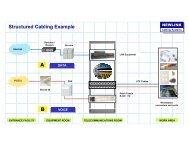
Typical “wired” LAN<strong>NEWLINK</strong><strong>Cabling</strong> <strong>Systems</strong>• Indoors– Horizontal <strong>Cabling</strong>– Backbone or Vertical <strong>Cabling</strong>CTATATCTCECTCTESCICTBuilding ABuilding B
WLAN Applications<strong>NEWLINK</strong><strong>Cabling</strong> <strong>Systems</strong>• Links Between Buildings (Campus Backbone)• Horizontal Links (Indoors / Outdoors)
Typical LAN Links<strong>NEWLINK</strong><strong>Cabling</strong> <strong>Systems</strong>• Inter-Building– Campus Backbone
Campus Backbone<strong>NEWLINK</strong><strong>Cabling</strong> <strong>Systems</strong>• Links Buildings without planned conduit or feasiblecabling routes• Extends the coverage of a wired UTP LAN avoidingFiber Optics cabling and equipment (require specialantennas)• Installation, Moves & Changes are easy to do
Horizontal Links<strong>NEWLINK</strong><strong>Cabling</strong> <strong>Systems</strong>• Allows the “Mobility Concept” for Workstations• Connects in a Client-to-Server fashion• Permits basic Pear-to-Pear networking• Operates as Signal Repeater extending the reach• Links workstations freely independently of conduit and outlets• Could result the best choice for complicated runnings• RF transmission is immune to EMI• Brings the connection to the outdoors environment
WLAN Linking Modes<strong>NEWLINK</strong><strong>Cabling</strong> <strong>Systems</strong>Ad-Hoc Mode• Small Office / Home Office• Small Workgroups• Distributed traffic Applications• Internet connection sharingInfrastructure Mode• Hybrid Networking Wired / <strong>Wireless</strong>• Uses APs : ACCESS POINTS• 5 Topologies and Applications• Public Areas
<strong>Wireless</strong> Elements<strong>NEWLINK</strong><strong>Cabling</strong> <strong>Systems</strong>ACCESS POINT ( AP )• Connects wired LAN networks cableadas with wirelessdevices and peripherals• Could be configured in 5-ways<strong>Wireless</strong>LAN
<strong>Wireless</strong> Elements<strong>NEWLINK</strong><strong>Cabling</strong> <strong>Systems</strong>WIRELESS ADAPTER ( PCI, CARDBUS )• Used for peripheral PCs, printers and equipment• Receives RF signals from the AP and transmits anomnidirectional signal back to the AP• Could be linked in-between with other peripheralswithout using an AP (Ad-Hoc mode)• Possess very low-power transmitters < 15 dBm
<strong>Wireless</strong> Elements<strong>NEWLINK</strong><strong>Cabling</strong> <strong>Systems</strong>RF Transmission• Used Transmission Frequencies ( 2.4 - 2.5 , 5.0 – 6.0 GHz)• Modulation ( OFDM, DSSS )• RF Channels ( 1, 2, 3, 11, 12 )• Data Rate ( 1, 5, 11, 24, 36, 54, 108 Mb/s )• Limited Power• Industry Standards Compliance ( IEEE 802.11 a / b / g )
RF Spectrum<strong>NEWLINK</strong><strong>Cabling</strong> <strong>Systems</strong>• Extreme Low Frequency ELF 300 Hz – 3 kHz• Very Low Frequency VLF 3 kHz – 30 kHz• Low Frequency LF 30 kHz – 300 kHz• Medium Frequency MF 300 kHz – 3 MHz• High Frequency HF 3 MHz – 30 MHz• Very High Frequency VHF 30 MHz – 300 MHz• Ultra High Frequency UHF 300 MHz – 3 GHz• Microwaves MW 3 GHz – 30 GHz• Milimetrics mm 30 GHz – 300 GHz
<strong>Wireless</strong> Standards<strong>NEWLINK</strong><strong>Cabling</strong> <strong>Systems</strong>IEEE 802.11a• Operational Frequency 5.5 a 6 GHz• Maximum Capacity 54 Mb/s• Distance up to 100 m @ 6 Mb/s• Distance up to 23 m @ 54 Mb/s• Separated paths for upstream / downstream• Up to 12 transmission channels, Tx y Rx simultaneously• OFDM – Orthogonal frequency division multiplexing• Effective Data rate = 30 Mb/s• Do not talk with IEEE 802.11b nor with IEEE 802.11 g
<strong>Wireless</strong> Standards<strong>NEWLINK</strong><strong>Cabling</strong> <strong>Systems</strong>IEEE 802.11b• Operational Frequency 2.4 a 2.5 GHz• Capacity up to 11 Mb/s• Distance up to 100 m @ 1 Mb/s• Distance up to 30 m @ 11 Mb/s• Shared upstream / downstream communication paths• Up to 3 transmission channels, Tx y Rx shared• DSSS – Direct-sequence spread-spectrum• Effective Data rate = 4 a 6 Mb/s• Coexist, do not communicates with IEEE 802.11a• Communicates fully with IEEE 802.11 g
<strong>Wireless</strong> Elements<strong>NEWLINK</strong><strong>Cabling</strong> <strong>Systems</strong>IEEE 802.11g• Up to 108 Mb/s using “G” mode• Up to 11 Mb/s on “b” mode• Operates in the 2.4 GHz band• 12 Transmition channels• Coexists with IEEE 802.11a• Comunicates with IEEE 802.11band IEEE 802.11g255436Mb/s11Is the newest technology developed and100% standarized50100meters
WLAN Configurations<strong>NEWLINK</strong><strong>Cabling</strong> <strong>Systems</strong>• ACCESS POINT• BRIDGING MODE• POINT - MULTIPOINT• CLIENT-SERVER5• REPEATER
Access Point Configuration<strong>NEWLINK</strong><strong>Cabling</strong> <strong>Systems</strong>Operates in Infrastructure Mode• Uses Point-Multipoint Links• Users get connection through APs• Data packet switching performs in the switch• Eachuserhavea WLAN interfacedependingupon PC type, uses PCMCIA CardBus or PCI
Point to Point Configuration<strong>NEWLINK</strong><strong>Cabling</strong> <strong>Systems</strong>Operates in Infrastructure ModeLAN A2000 m (*)LAN B• Creates a Point-to-Point Link. Called a BRIDGE.• Interconnects 2 LAN using <strong>Wireless</strong>• This configuration ties MAC addresses from each AP to setup a unique link(*) Distance reaches up to 2 km depending upon installing conditions and when usingexterior antennas
Point – Multipoint Scheme<strong>NEWLINK</strong><strong>Cabling</strong> <strong>Systems</strong>Operates en InfrastructureModeWLAN 3WLAN 4LAN 1WLAN 2WLAN 1• Creates Multiple WLAN arrays• Interconnects Multiple WLAN, up to 8 ACCESS POINTS• Each AP is tied to one LAN(*) Distance reaches up to 2 km depending upon installing conditions and when usingexterior omni and directional antennas
Client – Server Scheme<strong>NEWLINK</strong><strong>Cabling</strong> <strong>Systems</strong>Operates in Infrastructure ModeCLIENT APAPSERVER• Extends a dedicated <strong>Wireless</strong> Link coming from an AP wired to a LAN• Interconnects One LAN with One WLAN using wireless(*) Distance reaches up to 2 km depending upon installing conditions and when usingexterior antennas
Repeater Configuration<strong>NEWLINK</strong><strong>Cabling</strong> <strong>Systems</strong>Operates in Infrastructure Mode2000 m (*)WLAN 1• Extends the AP coverage displacing it• Interconnects One LAN with One WLAN using wireless(*) Distance reaches up to 2 km depending upon installing conditions and when usingexterior antennas
<strong>NEWLINK</strong> WIRELESSEQUIPMENT<strong>NEWLINK</strong><strong>Cabling</strong> <strong>Systems</strong>• Fullfills IEEE 802.11g• Operates up to 108 Mbps @ 2.4 GHz in SUPER G mode• Compatible with 802.11b @ 2.4GHz• Coexist with 802.11a @ 5.5GHz• Uses up to 12 RF channels• Throughput adjusted with distance and quantity of users• Offers new improved Security levels• Web Browser is accessible for configuration• Brings DHCP for Client access to an existing network
<strong>NEWLINK</strong> WIRELESSEQUIPMENT<strong>NEWLINK</strong><strong>Cabling</strong> <strong>Systems</strong>• ACCESS POINT• LAPTOP ADAPTER• DESKTOP ADAPTER
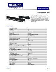
<strong>NEWLINK</strong><strong>Cabling</strong> <strong>Systems</strong>ACCESS POINT• Operates in G and b modes• Up to 108 Mb/s using super G mode linking APs• Up to 11 Mb/s using b mode• Supports encryptation WEP with 64 / 128 / 152 bits• 5 configuration models• 12 Transmission Channels• Brings further Security with built-in Firewall• Extended coverage using special antennasNEW-6500210
<strong>NEWLINK</strong><strong>Cabling</strong> <strong>Systems</strong>PCMCIA - CardBus• CardBus 32-bit Interface• Operates in Super-G and b mode• Up to 108 Mb/s using Super-G mode linking APs• Up to 11 Mb/s using “b”• Supports encryptation WEP with 64 / 128 / 152 bits• Built-in Antenna• Selectable Transmition Power Levels• Plug & Play setting upIdeal for Home, Office and Mobil Laptops in public spotsNEW-6500230
<strong>NEWLINK</strong><strong>Cabling</strong> <strong>Systems</strong>PCI ADAPTER• CardBus 32-bit PCI Interface• Operates in Super-G and b mode• Up to 108 Mb/s using Super-G mode linking APs• Up to 11 Mb/s using “b”• Supports encryptation WEP with 64 / 128 / 152 bits• 2 dBi gain removable Antenna• Selectable Transmition Power Levels• Plug & Play setting upIdeal for the Desktop PC where cabling resultsExpensive or hard to installNEW-6500240
Considerations<strong>NEWLINK</strong><strong>Cabling</strong> <strong>Systems</strong><strong>Wireless</strong> vs. Wired• WLAN technology is a tool design to coexist with LAN structured cablingsystems• The main WLAN advantage is : MOBILITY• In most cases, costing per unit, (Mega-bit / US$) wired points are more costeffective.This relationship is changing with time• Several special conditions give handicap for <strong>Wireless</strong> links• <strong>NEWLINK</strong> Super G Technology rises WLAN capacity in the Point to Pointschemes up to 108 Mb/s, equivaent to 75% of effective rate for full-duplex FastEthernet 100 Base-TX• Security levels on WLAN systems have been improved, always remain morevulnerable than wiredUSE WLAN EQUIPMENT WHEN IT BECOMES ASOLUTION, NOT A PROBLEM !
WLAN Installation<strong>NEWLINK</strong><strong>Cabling</strong> <strong>Systems</strong>Step by Step1. Check for Capacity Demand2. Define over a map the physical locations for each AP3. Make a Field Test to get real information. Benchmark.4. Adjust AP locations as needed. Use special antennas to getmore signal strength and coverage.5. Register and plot results and conclusions for future use6. Define a Security Plan and USE IT.
WLAN Installation<strong>NEWLINK</strong><strong>Cabling</strong> <strong>Systems</strong>Technical Isues1. Access Point devices and Antennas are placed over a Field Test basis.2. RF signals are affected in several ways by walls, furniture and somedecoration finishes. Thick materials and metals act as barriers.3. For better reception think that RF signals travels in a line patternfromtheAP tothemobileuserandavoidbrickwallsin suchpath.4. Fire retardant doors and materials are excellent, to content fire andRF signals also.5. Keep the APs in a safe place, far away from other RF sources asmicrowaves, radio equipment, amplifiers.
WLAN Installation<strong>NEWLINK</strong><strong>Cabling</strong> <strong>Systems</strong>Technical Isues6. Outdoor antennas increases RF Signal RECEPTION mainly.7. To connect external antennas use special Low-Loss Cables.8. Keep the AP as near as possible to the antenna.9. If you loss more signal strength in the cable that you gain with theantenna. Double check your locations.10. Use exterior antennas every time you want to keep a safe placementfor the AP but signl is not strong enough. ie. TelecommunicationsRoom, closed cabinet, etc.11. Use omni-directional antennas when you want to attend several usersfrom one AP.12. Use directional narrow antennas when you need long Point to PointLinks. i.e. Inter-building.
WLAN Installation<strong>NEWLINK</strong><strong>Cabling</strong> <strong>Systems</strong>Technical Isues12. Consider power supplies and network cablingup to the planned AP location.13. Begin your setup changing small parametersat a time. Once the transmission is properlyadjusted, implement security and otherfunctions.14. Test the wireless links at short distances andthen go slowly far away the AP registering thedifferent values for signal strenght andeffective throughput. Use a laptop or palm.Plot them in a map.15. Change the placement for APs and Test againto double check.
Antennas and Accesories<strong>NEWLINK</strong><strong>Cabling</strong> <strong>Systems</strong>In / Outdoor AntennasPoint - to- PointDirectional AntennaPoint - MultipointOmni-directional Antenna
Antennas and Accesories<strong>NEWLINK</strong><strong>Cabling</strong> <strong>Systems</strong>AP Antenna JumpersUltra Low-Loss CablesSurge Arrestor
<strong>NEWLINK</strong> WLAN<strong>NEWLINK</strong><strong>Cabling</strong> <strong>Systems</strong>
<strong>Wireless</strong> Standards<strong>NEWLINK</strong><strong>Cabling</strong> <strong>Systems</strong>IEEE 802.11aIEEE 802.11bIEEE 802.11gPHY Layer, 54 Mbps, OFDM @ 5 GHz.Range 23m @ 36 Mbps. Up to 12 channels.PHY Layer, 11 Mbps, DSSS @ 2.4 GHz, range 30m @ 11 Mbps.Up to 3 channels.PHY Layer, Compatible con 802.11b, usa OFDM @ 2.4 GHz.Do not make interference with 802.11a.Range 30m @ 48 Mbps Super “G”. Up to 11 ChannelsCoverage and throughput are function of Radio FrequencyTransmission variablesand subject to change withenvironmental conditions.
<strong>Wireless</strong> Standards<strong>NEWLINK</strong><strong>Cabling</strong> <strong>Systems</strong>IEEE 802.11aIEEE 802.11bIEEE 802.11gPHY Layer, 54 Mbps, OFDM @ 5 GHz.Range 23m @ 36 Mbps. Up to 12 channels.PHY Layer, 11 Mbps, DSSS @ 2.4 GHz, range 30m @ 11 Mbps.Up to 3 channels.PHY Layer, Compatible con 802.11b, usa OFDM @ 2.4 GHz.Do not make interference with 802.11a.Range 30m @ 48 Mbps Super “G”. Up to 11 ChannelsCoverage and throughput are function of Radio FrequencyTransmission variablesand subject to change withenvironmental conditions.