TIA / EIA - Newlink Cabling Systems
TIA / EIA - Newlink Cabling Systems
TIA / EIA - Newlink Cabling Systems
- No tags were found...

Create successful ePaper yourself
Turn your PDF publications into a flip-book with our unique Google optimized e-Paper software.
NEWLINK<strong>Cabling</strong> <strong>Systems</strong>J1NEWLINK ®Technical TrainingCopyrights 2003
ObjetiveNEWLINK<strong>Cabling</strong> <strong>Systems</strong>• Prepare participants to take the Certified Installer Test• Introduce concepts and requirements in Wireless Installations• Authorize Certified Installers for NEWMAX ® Warranty Program
BenefitsNEWLINK<strong>Cabling</strong> <strong>Systems</strong>• Get free technical support for your projects• Get NEWMAX Warranty for your jobs• Receive updates and news from our Industry• Receive Sales Leads contacts in your AreaAs a NEWMAX CERTIFIED INSTALLER receivethe benefits of our team of professionals
ContentsNEWLINK<strong>Cabling</strong> <strong>Systems</strong>• Telecommunications Basics• Physical Media : Copper, Fiber Optics• Standards reviews <strong>TIA</strong>/<strong>EIA</strong> 568, 569, 606• Testing Procedures for UTP and Fiber Optics• Wireless Networks Guidelines• Practice with NEWLINK products• NEWLINK Certification Test
Importance of Certified JobsNEWLINK<strong>Cabling</strong> <strong>Systems</strong>For the End-user• Good installation practice endorsement• Simplified Effective Troubleshooting• Organized network makes Moves & Changes easierFor the IT management• Defined life-cycle investment• Fullfillment of international standards• Follows globally used technology trends for future applications• Quality assurance, based on 100% circuits testingFor the Certified Installer• Well trained personnel saves money• NEWMAX 25-years Warranty gives ADDED VALUE
ScheduleNEWLINK<strong>Cabling</strong> <strong>Systems</strong>DAY 1• Introduction to Networking• Standard <strong>TIA</strong>/<strong>EIA</strong> 568 SummaryDAY 2• Testing UTP Installations• Standards 569 and 606 SummaryDAY 3• Wireless Networks• Hands-on Lab• Seminar Test
NEWLINK<strong>Cabling</strong> <strong>Systems</strong>Introduction to Networking
Telecommunication’s EvolutionNEWLINK<strong>Cabling</strong> <strong>Systems</strong>Electricity Based Telecommunications• 1844 Samuel Morse : Telegraph and Morse Code• 1860 Thomas A. Edison : Printing Telegraph• 1876 Alexander G. Bell : Telephone, starts the Bell Company• 1889 Almon B. Strowger : Dialer Telephone• 1890 Herman Hollerith : Punched Cards for Computing• 1905 Emile Baudot : Teletype (TTY) and Baudot Code• 1911 Guillermo Marconi : Radiotelegraphy• 1948 Bell Labs : Invention of the Transistor
Telecommunication’s EvolutionNEWLINK<strong>Cabling</strong> <strong>Systems</strong>• 1991 CAT 3 - 16 Mhz• 1994 CAT 4 –• 1995 First WLANs• 1997 CAT 5 - 100 Mhz• 1998 NEWLINK USA• 1999 Vo/IP Apllications• 2000 CAT 5E - 100 Mhz enhanced• 2002 CAT 6 - 250 Mhz• 2003 Fiber Optics Enhanced for 10 GigaCurrently a Task Force Group is working in thedevelopment of a 10Gigabit Ethernet overCopper (P802.an) standard expected by the end of 2006.
The Early Evolution was isolated…NEWLINK<strong>Cabling</strong> <strong>Systems</strong>SIGNALSVOICETelecommDATAIMAGES
Then Interacting…NEWLINK<strong>Cabling</strong> <strong>Systems</strong>Digitized Voice, VoIP,Music on demandVOICESIGNALSAccess Control, SmartCards, Digital SecurityDATADigital TV, Telex,Digital camerasBroadband VideoIMAGESFax, Multimedia, DVD,video-conference
Now IntegratedNEWLINKDictaphones<strong>Cabling</strong> <strong>Systems</strong>BeepersHospital Nurse Calling <strong>Systems</strong>Time Control <strong>Systems</strong>Access Control and SurveillanceAlarm panels, burglary, monitoringPersonal Protection <strong>Systems</strong>Automation, Instrumentation, ControlSIGNALSVOICEOutside Plant / Off-Premises <strong>Systems</strong>TelephonyIntercomsPublic Address <strong>Systems</strong> ( PAS)MusicCellular technologyDATAIMAGESAudio visual Integrated <strong>Systems</strong>CATV, CCTV, Digital TV, TV-SATHospitality <strong>Systems</strong>Medical ImagingInternet - IntranetData TransmissionCommunication ServicesWireless Networks
SimplifiedTelecommunications ModelNEWLINK<strong>Cabling</strong> <strong>Systems</strong>Message to be SentTransmitterTelecommPhysical MediaReceived MessageReceiver
The Basic Issue inTelecommunicationsNEWLINK<strong>Cabling</strong> <strong>Systems</strong>TransmitterInterruptionTelecommMessageReceiverDegradationDelaysDistortion
What Happens ?NEWLINK<strong>Cabling</strong> <strong>Systems</strong>TransmittedsignalTxAtenuationlength, frequencyReceived SignalRxLimited PowerNoise EMI, RFILimitedSensitivityNoise overcomes Signal !!
Telecommunication RequirementsNEWLINK<strong>Cabling</strong> <strong>Systems</strong>Signal Transmission LevelMedia Noise LevelSignal Reception LevelACR
Data TransmissionNEWLINK<strong>Cabling</strong> <strong>Systems</strong>Data Packet....11001110... Telecomm ....11001110...TransmitterReceiverInterferenceMessage IntegrityCommunication SpeedShared TimeConfirmation of DeliveryAutomatic RoutingEncoding / EncriptingLow Cost
InternetworkingGlobal Reach, multiprotocol, multi technology ...LANNEWLINK<strong>Cabling</strong> <strong>Systems</strong>LANPSTNLANV32, ISDNLANEthernet, Token RingFDDI, SONET, ARCnet, BACnet,LONtalkWEBISPX.25, TCP/IP, ATMFrame Relay, ISDNLANLAN
What is coming on ?NEWLINK<strong>Cabling</strong> <strong>Systems</strong>Complete Integration of Signals, Voice, Images, DataHigher SpeedsMore efficient ProtocolsAll Media Capacity UtilizationCrescent Use of Fiber OpticsSmarter Switches and EquipmentGreat development for Wireless Technologies
Vision ...NEWLINK<strong>Cabling</strong> <strong>Systems</strong>Integrated Telecommunications over a commonarchitecture, moving large amounts of Information(data packets) with reliability, quality over High-Speed Paths.
What is Structured <strong>Cabling</strong> ?NEWLINK<strong>Cabling</strong> <strong>Systems</strong>• Passive Installation of Cables and Connectors• Organized and Systematic• Follows International Standards and Procedures• Generic Model Open to diverse Applications• Use well defined Elements, parts and tools
STRUCTURED CABLINGNEWLINK<strong>Cabling</strong> <strong>Systems</strong>CODES & STANDARDSCABLES AND COMPONENTSSPACESCONNECTIVITYTESTING PROCEDURES
BENEFITSNEWLINK<strong>Cabling</strong> <strong>Systems</strong>MANUFACTURERSUSERSBUILDING CONTRACTORSSUMMARY :Telecomm Performance Level Guaranteed Documented Easy Moves & Changes Adm Simple Maintenance Generic <strong>Cabling</strong> brings Flexibility
STANDARDS & CODESNEWLINK<strong>Cabling</strong> <strong>Systems</strong>ANSI/<strong>TIA</strong>/<strong>EIA</strong> 568-B.x<strong>TIA</strong>/<strong>EIA</strong> 569 A<strong>TIA</strong>/<strong>EIA</strong> 606<strong>TIA</strong>/<strong>EIA</strong> 607TESTING PROCEDURES TSB-67ANSI :<strong>EIA</strong> :<strong>TIA</strong> :American National Standards InstituteElectronic Industries AllianceTelecommunications Industry Association
Standard 568NEWLINK<strong>Cabling</strong> <strong>Systems</strong>• ANSI/<strong>TIA</strong>/<strong>EIA</strong>-568-B.1, Commercial Building Telecommunications <strong>Cabling</strong> Standard: Part 1, General Requirements• ANSI/<strong>TIA</strong>/<strong>EIA</strong>-568-B.1-1, Minimum 4-Pair UTP and 4-Pair ScTP Patch Cable Bend Radius, Addendum 1 to ANSI/<strong>TIA</strong>/<strong>EIA</strong>-568-B.1• ANSI/<strong>TIA</strong>/<strong>EIA</strong>-568-B.1-2, Grounding and Bonding Specifications for Screened Horizontal <strong>Cabling</strong>, Addendum 2 to ANSI/<strong>TIA</strong>/<strong>EIA</strong>-568-B.1• ANSI/<strong>TIA</strong>/<strong>EIA</strong>-568-B.2, Commercial Building Telecommunications <strong>Cabling</strong> Standard: Part 2, Balanced Twisted-Pair <strong>Cabling</strong> Standard• ANSI/<strong>TIA</strong>/<strong>EIA</strong>-568-B.2-1, Transmission Performance Specifications for 4-Pair 100 Ohm Category 6 <strong>Cabling</strong>• ANSI/<strong>TIA</strong>/<strong>EIA</strong>-568-B.2-2, Addendum 2 to ANSI/<strong>TIA</strong>/<strong>EIA</strong>-568-B.2; Commercial Building Telecommunications <strong>Cabling</strong> Standard -Part 2: BalancedTwisted-Pair <strong>Cabling</strong> Components• ANSI/<strong>TIA</strong>/<strong>EIA</strong>-568-B.3, Commercial Building Telecommunications <strong>Cabling</strong> Standard: Part 3, Optical Fiber <strong>Cabling</strong> Components• ANSI/<strong>TIA</strong>/<strong>EIA</strong>-568-B.3-1, Additional Transmission Performance Specifications for 50/125 m Optical Fiber CablesStandard 569• ANSI/<strong>TIA</strong>/<strong>EIA</strong>-569-A, Standard, Commercial Building Standard for Telecommunications Pathways and Spaces• ANSI/<strong>TIA</strong>/<strong>EIA</strong>-569-A-1, Addendum 1 to ANSI/<strong>TIA</strong>/<strong>EIA</strong>-569-A; Perimeter Pathways Addendum• ANSI/<strong>TIA</strong>/<strong>EIA</strong>-569-A-2, Addendum 2 to ANSI/<strong>TIA</strong>/<strong>EIA</strong>-569-A; Furniture Pathways Fill Addendum• ANSI/<strong>TIA</strong>/<strong>EIA</strong>-569-A-3, Addendum 3 to ANSI/<strong>TIA</strong>/<strong>EIA</strong>-569-A; Revision to Clause 4.3, Access Floors• ANSI/<strong>TIA</strong>/<strong>EIA</strong>-569-A-4, Poke-Thru Fitting Addendum• ANSI/<strong>TIA</strong>/<strong>EIA</strong>-569-A-5, Addendum 5 to ANSI/<strong>TIA</strong>/<strong>EIA</strong>-569-A; Commercial Building Standard For Telecommunications Pathways and Spaces• ANSI/<strong>TIA</strong>/<strong>EIA</strong>-569-A-6, Addendum 6 to ANSI/<strong>TIA</strong>/<strong>EIA</strong>-569-A; Multi-tenant Pathways and Spaces Addendum• ANSI/<strong>TIA</strong>/<strong>EIA</strong>-569-A-7, Commercial Building Telecommunications Pathways and Spaces, Addendum 7 -Cable Trays and WirewaysStandard 606 -607• ANSI/<strong>TIA</strong>/<strong>EIA</strong>-606, Administration Standards for Commercial Telecommunications Infrastructure (Pending)• ANSI/<strong>TIA</strong>/<strong>EIA</strong>-606-A, Administration Standard for Commercial Telecommunications/Infrastructures (Pending)• ANSI/<strong>TIA</strong>/<strong>EIA</strong>-607, Commercial Building Grounding and Bonding Requirements for Telecommunications
StandardsNEWLINK<strong>Cabling</strong> <strong>Systems</strong>
NEWLINK<strong>Cabling</strong> <strong>Systems</strong>
<strong>TIA</strong> / <strong>EIA</strong> - 568NEWLINK<strong>Cabling</strong> <strong>Systems</strong>Telecommunications Standard forCommercial Buildings
<strong>TIA</strong> / <strong>EIA</strong> - 568NEWLINK<strong>Cabling</strong> <strong>Systems</strong>Parts• <strong>TIA</strong> / 568 B.1 - Structured <strong>Cabling</strong> Guidelines• <strong>TIA</strong> / 568 B.2 - Specifications for Manufacturing UTP• <strong>TIA</strong> / 568 B.3 - Specifications for Fiber Optics + Components
<strong>TIA</strong> / <strong>EIA</strong> - 568NEWLINK<strong>Cabling</strong> <strong>Systems</strong>Criteria• Mandatory :must be implemented• Desirable :is a recommendation
<strong>TIA</strong> / <strong>EIA</strong> - 568NEWLINK<strong>Cabling</strong> <strong>Systems</strong>Purpose• Specify Generic <strong>Cabling</strong> System• Multiuser, multiparty environment• Makes easier installation planning• Defines minimum performance levels
<strong>TIA</strong> / <strong>EIA</strong> - 568NEWLINK<strong>Cabling</strong> <strong>Systems</strong>Scope• Commercial Buildings• Campus Backbone• Area up to 1’000,000 m2• Population up to 50,000 usuarios• Application for Voice, Data, Signaling, Video, Audio• 10-year Life Cycle Horizon
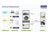
<strong>TIA</strong> / <strong>EIA</strong>-568-B.1NEWLINK<strong>Cabling</strong> <strong>Systems</strong>ElementsHORIZONTAL CABLINGVERTICAL CABLINGWORK AREA TelecommTELECOMMUNICATIONS ROOM / CLOSETEQUIPMENT ROOMSERVICES ENTRY
<strong>TIA</strong> / <strong>EIA</strong> – 568-B.1NEWLINK<strong>Cabling</strong> <strong>Systems</strong>ElementsWATRWork AreaTelecommunications RoomWAICERIntermediate ClosetEquipment RoomTRWASEService EntryTRERTRTRSEICTRBuilding ABuilding B
<strong>TIA</strong> / <strong>EIA</strong> – 568-B.1NEWLINK<strong>Cabling</strong> <strong>Systems</strong>ElementsHUBVoiceDataHorizontal <strong>Cabling</strong>
<strong>TIA</strong> / <strong>EIA</strong> – 568-B.1NEWLINK<strong>Cabling</strong> <strong>Systems</strong>ElementsVertical <strong>Cabling</strong>
<strong>TIA</strong> / <strong>EIA</strong> – 568-B.1NEWLINK<strong>Cabling</strong> <strong>Systems</strong>Elements• Space destinated to the users of peripheralequipment.• As a rule of thumb an Area of 10 sq. Meter mustbe destinated for each Work Area.• Work Area defines where to put the faceplatesloaded with jacks or connectors to be useradministrated.Work Area / Workstation
<strong>TIA</strong> / <strong>EIA</strong> – 568-B.1NEWLINK<strong>Cabling</strong> <strong>Systems</strong>Elements• Destinated to host all the IT processing equipment.• This Area is to be used by the Servers, PBX and all theequipment related to the IT Processing.• Areas are determined by the <strong>TIA</strong>/<strong>EIA</strong> 569 standard• Depending upon the size and complexity of the installation itcould performs also as a TELECOMMUNICATIONS ROOM.Equipment Room
<strong>TIA</strong> / <strong>EIA</strong> – 568-B.1NEWLINK<strong>Cabling</strong> <strong>Systems</strong>Elements• Destinated to Racks, Cabinets containing the Cross-connectsand some networking equipment at the beginning of theHorizontal <strong>Cabling</strong>.• Areas are determined by the <strong>TIA</strong>/<strong>EIA</strong> 569 standard• Depending upon the size and complexity of the installation itcould perform as a EQUIPMENT ROOM at the same time.Telecommunications Room
<strong>TIA</strong> / <strong>EIA</strong> – 568-B.1NEWLINK<strong>Cabling</strong> <strong>Systems</strong>Elements• Contains the Entry Cross-Connect thatisolates external lines from internalLANs.• Electrical protection, fuses andsuppresors shall be considered at thispoint as required by the NationalElectrical Code.LANOutsideServices• Define the Limit of Responsibilities forThird Party Outside Services.Services Entry
<strong>TIA</strong> / <strong>EIA</strong> – 568-B.1NEWLINK<strong>Cabling</strong> <strong>Systems</strong>ElementsWATRWork AreaTelecommunications RoomWAICERIntermediate ClosetEquipment RoomTRWASEService EntryTRERTRTRSEICTRBuilding ABuilding B
<strong>TIA</strong> / <strong>EIA</strong> – 568-B.1NEWLINK<strong>Cabling</strong> <strong>Systems</strong>Horizontal <strong>Cabling</strong> Guidelines• Extends from Telecom Room to Work Area• Includes : Cross-connects, <strong>Cabling</strong>, Connectors• Optionally : MuTOA, Consolidation Points• Maximum Length• Channel Configuration (including Patch Cords) = 100 m• Permanent Link (without Patch Cords) = 90 m• Recommended number of outlets• 2 outlets per Work Area as minimum• 1 shall be CAT 3 or superior• 1 shall be CAT 5E or superior1 12 2334455667788
<strong>TIA</strong> / <strong>EIA</strong> – 568-B.1NEWLINK<strong>Cabling</strong> <strong>Systems</strong>Cross-Connection• Links Cable Segments using Patch Cords or Wire Jumpers• Could consist of Patch Panels or other IDC connecting devices• Exists in 3 hierarchy levels : Horizontal XC, Intermediate XC, Main XC
<strong>TIA</strong> / <strong>EIA</strong> – 568-B.1NEWLINK<strong>Cabling</strong> <strong>Systems</strong>Horizontal <strong>Cabling</strong> Guidelines• Minimum consider the following <strong>Systems</strong> at Design Stage: Voice /Phone, Data, Video, Other (Fire Alarm, BAS, etc)• Horizontal <strong>Cabling</strong> is the most extensive, hard to modify installation,thus select pathways and routes is critical over the entire life-cycle.• Consider extra room for future growing and changes.• Follows all the guidelines for Pathways and Space Use as perANSI/<strong>EIA</strong>/<strong>TIA</strong>-569 A.
<strong>TIA</strong> / <strong>EIA</strong> – 568-B.1NEWLINK<strong>Cabling</strong> <strong>Systems</strong>Horizontal <strong>Cabling</strong> Guidelines• Maximum distance covered by Horizontal <strong>Cabling</strong> is 100 meter.• A maximum of 90 meter is allowed from Telecommunications Room toWork Area.• Patch cord’s length shall no exceed 5 meter in each segment end.• A total of 10 meter is permited for all Patch Cords over theHorizontal segment.• Additional restrictions apply when using optional Consolidation Point orMuTOA configurations.
<strong>TIA</strong> / <strong>EIA</strong> – 568-B.1Horizontal <strong>Cabling</strong> GuidelinesNEWLINK<strong>Cabling</strong> <strong>Systems</strong>ATCTMIN: 15 mATMIN: 5 mATMAX: 90 mCPConsolidation Point(optional)STAR Topology
<strong>TIA</strong> / <strong>EIA</strong> – 568-B.1NEWLINK<strong>Cabling</strong> <strong>Systems</strong>Horizontal <strong>Cabling</strong> Guidelines• Optional Maximum One Consolidation Point per Horizontal Link.• Minimum Distance from Telecommunications Room to ConsolidationPoint is 15 meter.• Minimum Distance from Consolidation Point to Work Area is 5 meter.• All connections at Consolidation Point shall be of the IDC type.• Splices are forbidden on UTP or STP copper cables.• Up to two (2) splices are allowed when using Optical Fiber.
<strong>TIA</strong> / <strong>EIA</strong> – 568-B.1NEWLINK<strong>Cabling</strong> <strong>Systems</strong>Horizontal <strong>Cabling</strong> Guidelines• UTP cables must be terminated with its 4 pair completed connected atboth ends of the cable.• RJ45 jacks with Eight (8) conductors must be used for all HorizontalTerminations.• All connectors shall be of the IDC kind termination.• Shielded-jacket cables must connect the shield at one end only. Whenconnecting both ends an unwanted antenna effect appears.
<strong>TIA</strong> / <strong>EIA</strong> – 568-B.1NEWLINK<strong>Cabling</strong> <strong>Systems</strong>Horizontal <strong>Cabling</strong> Guidelines• All the cables routed and connected at the Work Area shall have acorrespondent connection at the Telecommunications Room.
<strong>TIA</strong> / <strong>EIA</strong> – 568-B.1NEWLINK<strong>Cabling</strong> <strong>Systems</strong>Horizontal <strong>Cabling</strong> Guidelines• It is strongly recommended that Work Areas be attended from thecloser Telecommunications Room located on the same floor.• Do not install any electrical service inside the telecommunicationsconduit or raceways.• Keep recommended distances between power circuits and devices andthe bundles of communications cables.• For Testing and Certification purposes Structured <strong>Cabling</strong> <strong>Systems</strong>ends when it is connected to an Active Equipment.• Splitters, adapters and connectors other than RJ45 plugs areconsidered not part of the Structured <strong>Cabling</strong> <strong>Systems</strong>.
<strong>TIA</strong> / <strong>EIA</strong> – 568-B.1NEWLINK<strong>Cabling</strong> <strong>Systems</strong>Horizontal <strong>Cabling</strong> Guidelines• RECOMMENDED CABLES– Twisted-pair, balanced, 4-pair, 100 Ohm :UTP - Unshielded Twisted-PairScTP – Screened Twisted Pair– 2 Optical Fibers (Tx / Rx) :multimode 50 /125 ummultimode 62,5/125 um• RECOGNIZED CABLES– ScTP with 150 ohm called: STP-A– Hybrid Cables (UTP + FO) in one jacket, individually each cable shallmeet ANSI/<strong>EIA</strong>/<strong>TIA</strong>-568-B.2
<strong>TIA</strong> / <strong>EIA</strong> – 568-B.1Horizontal <strong>Cabling</strong> GuidelinesNEWLINK<strong>Cabling</strong> <strong>Systems</strong>• UTP - Unshielded Twisted-Pair• Four (4) Balanced Pair cable• 100 Ohms Characteristic Impedance• Intereference Protection by Twistingthe conductors• Most used, most cost-effective• Performance Categories– 3 up to 16Mhz– 5E up to 100Mhz– 6 up to 250Mhz
<strong>TIA</strong> / <strong>EIA</strong> – 568-B.1Horizontal <strong>Cabling</strong> GuidelinesNEWLINK<strong>Cabling</strong> <strong>Systems</strong>• Multimode Optical Fiber:– 50 um o 62.5 um / 125 um core/cladding– Maximum Length: 90 Mts– Uses LED as light source– Wavelength / Modal Bandwidth• 850 nm (3.5 db/km) / 200 Mhz-km• 1300 nm (1.0 db/km) / 500 Mhz-km
<strong>TIA</strong> / <strong>EIA</strong> – 568-B.1NEWLINK<strong>Cabling</strong> <strong>Systems</strong>ElementsWATRWork AreaTelecommunications RoomWAICERIntermediate ClosetEquipment RoomTRWASEService EntryTRERTRTRSEICTRBuilding ABuilding B
<strong>TIA</strong> / <strong>EIA</strong> – 568-B.1NEWLINK<strong>Cabling</strong> <strong>Systems</strong>Vertical <strong>Cabling</strong> - Backbone• Includes interconnections between:– Horizontal Cross-connects– Intermediate Cross-Connects– Main Cross-connectsXC• All the links between Horizontal <strong>Cabling</strong>sand Backbone <strong>Cabling</strong> must use Crossconnection.MXCIC
<strong>TIA</strong> / <strong>EIA</strong> – 568-B.1NEWLINK<strong>Cabling</strong> <strong>Systems</strong>Vertical <strong>Cabling</strong> - Backbone• Use Hierarchical Star TopologyMXC• A maximum of two levels ispermittedIC• Star arrangement makestroubleshooting easierXCXCXCHC HC HC
<strong>TIA</strong> / <strong>EIA</strong> – 568-B.1NEWLINK<strong>Cabling</strong> <strong>Systems</strong>Vertical <strong>Cabling</strong> - Backbone• Interconnects all theTelecommunications Rooms with theEquipment Room• Connect the Service Entry with theBackbone matrixBldg B• Includes inter-building links inCampus configurationBldg ABldg C
<strong>TIA</strong> / <strong>EIA</strong> – 568-B.1NEWLINK<strong>Cabling</strong> <strong>Systems</strong>Vertical <strong>Cabling</strong> - Backbone• Select the routes using the <strong>TIA</strong>/<strong>EIA</strong>-569A guidelines• All cross connects shall be of the IDC type• Optical Fiber could be spliced several times everytime TotalInsertion Loss remains below the Maximum allowed• Combinedlenghtofpatchcordtonotexceed15 m• Active equipment could be used to extend the range for theVertical <strong>Cabling</strong>.
<strong>TIA</strong> / <strong>EIA</strong> – 568-B.1Vertical <strong>Cabling</strong> - BackboneNEWLINK<strong>Cabling</strong> <strong>Systems</strong>• Recognized Cables– Multipair UTP de 22 – 24 AWG– Optical Fiber Multimode– Optical Fiber Single-mode• Distancias Máximas:– UTP 800 m - Voice– UTP 90 m - Data– Multimode 2000 m– Single-mode 3000 m
<strong>TIA</strong> / <strong>EIA</strong> – 568-B.1Backbone DistancesNEWLINK<strong>Cabling</strong> <strong>Systems</strong>HCAMCESHCBICCHorizontal Cross-connect ...... HCIntermediate X-connect ..... ICMain Cross-connect .......... MCA B CUTP Balanced - VOICE800300500UTP Balanced - DATA909090Fiber Multimode20003001700Fiber Single-mode30003002700
<strong>TIA</strong> / <strong>EIA</strong> – 568-B.1NEWLINK<strong>Cabling</strong> <strong>Systems</strong>Vertical <strong>Cabling</strong> - Backbone• Optical Fiber Single-mode:• 8.3 um / 125 um core/cladding• Distance 3,000 m (50 Km in telephony)• Use LASER emitters• Wavelenght / Bandwidth– 1310 nm (1.0 db/km) / MHz-km “unlimited”– 1383 nm (1.0 db/km) / MHz-km “unlimited”– 1550 nm (1.0 db/km) / MHz-km “unlimited”
<strong>TIA</strong> / <strong>EIA</strong> – 568-B.1NEWLINK<strong>Cabling</strong> <strong>Systems</strong>Telecommunication Room• Area destinated to Telecomunications Services Only• Its main function is to host <strong>Cabling</strong> endings and interconnects• Host all the “Cross Connects” :• Horizontal – Active Equipment• Horizontal - Vertical (voice connections)• Vertical – Active Equipment• Vertical - Vertical (Intermediate Connects)• Dimensions and specifications by <strong>EIA</strong>/<strong>TIA</strong>-569 A
<strong>TIA</strong> / <strong>EIA</strong> – 568-B.1NEWLINK<strong>Cabling</strong> <strong>Systems</strong>Work Area• Designed for user flexibility• Uses a minimum of 2 outlets per each Workstation• Permits optionally the use of MuTOA (Multiuser TelecommOutlet Assemblies)• The use of MuTOA use a special formula to compute themaximum patch cord’s length.• For design purposes consider an Area of 10 sq. Meter foreach Work Area.
<strong>TIA</strong> / <strong>EIA</strong> – 568-B.1Equipment RoomNEWLINK<strong>Cabling</strong> <strong>Systems</strong>• Must contain the main “HUB”• Could contain the MCC and share functions ofTelecommunication’s Room in the same space.• Contains the Servers, PBX, Telecom Equipment, all the ITequipment.• Generally requires a controlled temperature, air humidity,power stability, safety, etc.• Must be designed following <strong>TIA</strong>/<strong>EIA</strong>-569 Guidelines
<strong>TIA</strong> / <strong>EIA</strong> – 568-B.2NEWLINK<strong>Cabling</strong> <strong>Systems</strong><strong>Cabling</strong> ComponentsMEDIA : UTP, coaxial, multi-pair, optical fiberCONNECTORS : jacks, patch panels, plugsORGANIZERS : vertical, horizontal, front/rearSUPPORT : cabinets, racks, boxes, shelves
<strong>TIA</strong> / <strong>EIA</strong> – 568-B.2NEWLINK<strong>Cabling</strong> <strong>Systems</strong><strong>Cabling</strong> ComponentsRequisites for Connectors:– Materials– Smoke Emission– Dimensions and tolerances– Electrical characteristics– Performance by <strong>TIA</strong>/<strong>EIA</strong>-568-B.3– Marking CAT 5, 6, OFNR, etc– Connect / Disconnect # of cycles
<strong>TIA</strong> / <strong>EIA</strong> – 568-B.2NEWLINK<strong>Cabling</strong> <strong>Systems</strong><strong>Cabling</strong> ComponentsRequisites for the cable:– Conductor Materials– Jacket materials– Fire Resistance Properties– Dimensions and Tolerances– Wire section area AWG– Electrical characteristics– Performance by <strong>TIA</strong>/<strong>EIA</strong>-568-B.3– Marking CAT 5, 6, OFNR, etc
<strong>TIA</strong> / <strong>EIA</strong> – 568-B.2NEWLINK<strong>Cabling</strong> <strong>Systems</strong><strong>Cabling</strong> Components• Connecting Devices in Structured<strong>Cabling</strong> <strong>Systems</strong> shall be of theIDC (Insulation DisplacementConnection) type.• Including:– Jacks in Outlets– Jacks in Patch Panels– Connecting Blocks– Consolidation or Transition Points
NEWLINK<strong>Cabling</strong> <strong>Systems</strong>
NEWLINK<strong>Cabling</strong> <strong>Systems</strong>
<strong>TIA</strong> / <strong>EIA</strong> - 568NEWLINK<strong>Cabling</strong> <strong>Systems</strong>Media :TWISTED PAIRS
Bandwidth, Categories & ClassesNEWLINK<strong>Cabling</strong> <strong>Systems</strong>Bandwidth(MHz)ANSI/<strong>TIA</strong>/<strong>EIA</strong>Data RateAplication1CAT 164 kbpsPOTS, <strong>EIA</strong> 23210CAT 24 MbpsToken Ring16CAT 310 MbpsEthernet20CAT 425 MbpsARCNet, ATM100CAT 5100 MbpsFast Ethernet100CAT 5E155 Mbps155 ATM250CAT 6Class EGigabit Ethernet600*CAT 7*Class FClass F
<strong>TIA</strong> / <strong>EIA</strong> – 568NEWLINK<strong>Cabling</strong> <strong>Systems</strong>UTP Cable – 4 Pairs1234567812345678
<strong>TIA</strong> / <strong>EIA</strong> – 568-B.1NEWLINK<strong>Cabling</strong> <strong>Systems</strong>Standard TerminationsPar 2Par 3Par 1Par 41 2 3 4 5 6 7 8T568APar 3Par 2Par 1Par 41 2 3 4 5 6 7 8T568B
<strong>TIA</strong> / <strong>EIA</strong> – 568-B.1, B.2<strong>Cabling</strong> ComponentsNEWLINK<strong>Cabling</strong> <strong>Systems</strong>• Patch Cords shall use stranded cables• Must match the same Category as theHorizontal UTP Cable and connectors.• Must be NEWLINK in order to includedthem for the NEWMAX 25-years Warranty• Performance Limits are the same that thosewho corresponds to UTP solid conductorsexcept by the Insertion Loss / Attenuationthat is greater.
<strong>TIA</strong> / <strong>EIA</strong> – 568-B.1NEWLINK<strong>Cabling</strong> <strong>Systems</strong>Attenuation• Decayofthesignalpowermeasuredby comparing Input against Outputlevels.• Represents the power of signalavailable at the far end of thecable.∆P = -10 logwhere S 2 < S 1S 2S 1• Is expressed in decibels (dB).S 1 S 2
<strong>TIA</strong> / <strong>EIA</strong> – 568-B.1NEWLINK<strong>Cabling</strong> <strong>Systems</strong>Attenuation• Each 3 dB step power doubles• Each 10 dB step power multiplies by 10Example:• Output Level = 0 dB• Media Attenuation = -25 dB• Received Signal (%) = 0,31% !!P100%50%25%12,5% 6,25%-3 -6 -9 -12dB
<strong>TIA</strong> / <strong>EIA</strong> – 568-B.1NEWLINK<strong>Cabling</strong> <strong>Systems</strong>AttenuationDepends on :– Media Type– Transmission Frequency– Temperature (mainly with UTP)– Geometry, Shape (both UTP and Fiber)– Conductor Section (AWG), Core Type (FO)– Electrical Characteristics– Humidity– Other
<strong>TIA</strong> / <strong>EIA</strong> – 568NEWLINK<strong>Cabling</strong> <strong>Systems</strong>AttenuationFrequencyCat 3 (dB)Cat 5 (dB)Cat 6 (dB)1.02.62.12.14.05.64.03.910.09.76.36.216.013.18.27.820.0--9.28.831.25--11.511.1100.0--21.620.7200----30.4250----32.0
<strong>TIA</strong> / <strong>EIA</strong> – 568NEWLINK<strong>Cabling</strong> <strong>Systems</strong>AttenuationdBATTENUATION0 50 100 150 200 250Frequency (MHz)
<strong>TIA</strong> / <strong>EIA</strong> – 568-B.1NEWLINK<strong>Cabling</strong> <strong>Systems</strong>Next-End CrossTalk: NEXT• Unwanted Signal coupling between adjacent pairs• Is expressed in dB• Diminishes with the Frequency• Crosstalk exists only in metallic conductors• Larger NEXT values indicates more capacity to transmithigher power levels without interference with other pairs• NEXT failures founded during Testing process correspond tocable and connector terminations mainly
<strong>TIA</strong> / <strong>EIA</strong> – 568NEWLINK<strong>Cabling</strong> <strong>Systems</strong>NEXTFrequencyCat 3 (dB)Cat 5 (dB)Cat 6 (dB)1.041.060.065.04.032.054.864.110.026.048.557.816.023.045.254.620.0--43.753.131.25--40.550.0100.0--32.341.8200----36.9250----35.3
<strong>TIA</strong> / <strong>EIA</strong> – 568NEWLINK<strong>Cabling</strong> <strong>Systems</strong>NEXTdBNEXT0 50 100 150 200 250Frequency (MHz)
<strong>TIA</strong> / <strong>EIA</strong> – 568NEWLINK<strong>Cabling</strong> <strong>Systems</strong>Available BandwidthdBNEXTACRATTENUATION0 50 100 150 200 250Frequency (MHz)
<strong>TIA</strong> / <strong>EIA</strong> TSB-67NEWLINK<strong>Cabling</strong> <strong>Systems</strong>TechnicalSpecifications forField Testing
<strong>TIA</strong> / <strong>EIA</strong> TSB-67IntroductionNEWLINK<strong>Cabling</strong> <strong>Systems</strong>• Define the different Tests that are required for UTP and FO• Documents Quality Controls• Designed for the <strong>TIA</strong>/<strong>EIA</strong>-568 InstallationsNOTEFormally the requirements for the TSB-67 have been incorporated to the body of the<strong>TIA</strong>/<strong>EIA</strong>-568.B-2 standard, but it is mentioned frequently as a reference.
<strong>TIA</strong> / <strong>EIA</strong> TSB-67ScopeNEWLINK<strong>Cabling</strong> <strong>Systems</strong>• TSB 67 Specifies the Performance requirements for a Link• Defines:• Test Models• Test Procedures• Results Interpretation• Tester automatically contrast results with laboratoryparameters
<strong>TIA</strong> / <strong>EIA</strong> TSB-67ApplicabilityNEWLINK<strong>Cabling</strong> <strong>Systems</strong>Suitable for :• 4-Balaced Pairs type UTP, 100 Ohms• 4-Balaced Pairs type ScTP, 100 Ohms Cable de 4 pares• Only applicable for Horizontal <strong>Cabling</strong>• Specific Tests exist for each Category of cable: 3, 5E, 6
<strong>TIA</strong> / <strong>EIA</strong> TSB-67The Points of FailureNEWLINK<strong>Cabling</strong> <strong>Systems</strong>35678921415 16101411APOINT OF FAILURE BY ORIGIN:• INSTRUMENTSA, B• PATCH CORDS 1, 2, 3 – 9, 10, 11• WORKMANSHIP 5 , 7• PATCH PANEL / JACKS 4 , 8•CABLE 6B
<strong>TIA</strong> / <strong>EIA</strong> TSB-67The Workmanship on the Patch PanelNEWLINK<strong>Cabling</strong> <strong>Systems</strong>Excesive untwist length• Bad color addressing• Different color schemefor the same cable endsPoor Insertion / IDC
<strong>TIA</strong> / <strong>EIA</strong> TSB-67The Workmanship on the RJ-45 JackNEWLINK<strong>Cabling</strong> <strong>Systems</strong>Excessive untwistedPoor Insertion / IDC• T568A Scheme• T568B Scheme
<strong>TIA</strong> / <strong>EIA</strong> TSB-67Bandwidth, Categories & ClassesNEWLINK<strong>Cabling</strong> <strong>Systems</strong>Bandwidth(MHz)ANSI/<strong>TIA</strong>/<strong>EIA</strong>Data RateApplication1CAT 164 kbpsPOTS, <strong>EIA</strong> 23210CAT 24 MbpsToken Ring16CAT 310 MbpsEthernet20CAT 425 MbpsARCNet, ATM100CAT 5100 MbpsFast Ethernet100CT 5E155 Mbps155 ATM250CAT 6Class EGigabit Ethernet600*CAT 7*Class FClass F
<strong>TIA</strong> / <strong>EIA</strong> TSB-67Testing PracticesNEWLINK<strong>Cabling</strong> <strong>Systems</strong>Standard Models :• Permanent Link• Channel Test
<strong>TIA</strong> / <strong>EIA</strong> TSB-67Testing PracticesNEWLINK<strong>Cabling</strong> <strong>Systems</strong>• Permanent Link– Cross Connect– UTP Cable permanently installed– Outlet Jacks• Channel Test– All of the Above plus:– Patch cord in the Cross-connect– Patch cable used in the Work Area
<strong>TIA</strong> / <strong>EIA</strong> TSB-67Testing PracticesNEWLINK<strong>Cabling</strong> <strong>Systems</strong>PERMANENT LINKXCTelecomm.Closet90 mFpWork AreaUse the InstrumentPatch Cords
<strong>TIA</strong> / <strong>EIA</strong> TSB-67Testing PracticesNEWLINK<strong>Cabling</strong> <strong>Systems</strong>CHANNEL TESTXCTelecomm.Closet90 mFpWork AreaUse the Patch Cordsdestinated to such specificWork Area
<strong>TIA</strong> / <strong>EIA</strong> TSB-67Testing PracticesNEWLINK<strong>Cabling</strong> <strong>Systems</strong>During Installation– Check for continuity inmediatly after connecting both ends ofthe cable– More than 80% of the fails corresponds to an unpropertermination (open wires, shorted wires, swapping pairs)After Job Conclusion– Test First for Permanent Link at corresponding Category– If results are OK Test then for Channel configuration– Use current calibrated instruments only
<strong>TIA</strong> / <strong>EIA</strong> TSB-67Testing PracticesNEWLINK<strong>Cabling</strong> <strong>Systems</strong>• Testing CAT 6 and CAT 5E links requires improved accuracy fromportable certification equipment.• Performance Level III Field Testers are required.• It is very important to consider that equipment must be in optimaloperating conditions to get valid measurements.• Set Calibration and good condition for connectors or adapters is amust.
<strong>TIA</strong> / <strong>EIA</strong> TSB-67DefinitionsNEWLINK<strong>Cabling</strong> <strong>Systems</strong>Wire Map / MappingCheck straight termination pin-to-pin.Verify: Proper pin termination at each end, Continuity to the remote end, Shorts between anytwo or more conductors, Crossed pairs, Split pairs, Reversed pairs, Shorted pairs.T568AT568B12345678Pair 1 Pair 1Pair 2 Pair 3Pair 3 Pair 2Pair 4 Pair 4
<strong>TIA</strong> / <strong>EIA</strong> TSB-67DefinitionsNEWLINK<strong>Cabling</strong> <strong>Systems</strong>ScTP Shield ContinuityThis Test applies only for Shielded Cables. The test consist in verify the consistency forthe metallic shield covering the telecommunications pairs.
<strong>TIA</strong> / <strong>EIA</strong> TSB-67DefinitionsNEWLINK<strong>Cabling</strong> <strong>Systems</strong>Length / NVP BasedDepending upon the Model under Test, it allows two different results:• 100 m including all the elements from patch cord to patch cord• 90 m correspondent only to the Permanent Link segmentComplete Channel TestMaximum 100 mPermanent Link TestMaximum 90 m
<strong>TIA</strong> / <strong>EIA</strong> TSB-67DefinitionsNEWLINK<strong>Cabling</strong> <strong>Systems</strong>Insertion Loss (Attenuation)Is the measure representing the level of signal loss along the different elements “inserted” inthe link.Insertion Loss includes the losses of the patch cords when running the Channel Test.It is expressed in terms of Decibels (dB) for easy comparission.-L 2dB-L6dB-L 1dB-L 3dB -L 4dB-L dB5-L 7dBInsertion Losses = E Li
<strong>TIA</strong> / <strong>EIA</strong> TSB-67DefinitionsNEWLINK<strong>Cabling</strong> <strong>Systems</strong>CROSS-TALKWhen a current flows through a wire, an electromagnetic fieldis created which can interfere with signals on adjacent wires.As frequency increases, this effect becomes stronger.Each pair is twisted because this allows opposing fields in thewire pair to cancel each other. The tighter the twist, the moreeffective the cancellation and the higher the data ratesupported by the cable.Maintaining this twist ratio is the single most importantfactor for a successful installation.Interferent Magnetic field is proportionalto the current in the conductor and growswith the frequency
<strong>TIA</strong> / <strong>EIA</strong> TSB-67DefinitionsNEWLINK<strong>Cabling</strong> <strong>Systems</strong>CROSS-TALKCross-Talk is the interference transfered from a telecommunication’s pair to other adjacentpairs. Those pairs may belong to the same cable in a multi-pair cable or to a bundle of cables(allien cross-talk).Cross-Talk depends upon the transmission power level, cable geometry and the impedance ofthe telecommunication conductors. It also increases with an increase of frequency andlength (when it is evaluated in the far-end of the cable).It is expressed in dB showing the relationship between the received-to-transmitted signalratio.Coupled InterferenceCoupled InterferenceNEXTFEXTTX SignalWeaked Signal
<strong>TIA</strong> / <strong>EIA</strong> TSB-67DefinitionsNEWLINK<strong>Cabling</strong> <strong>Systems</strong>NEXT / Near End Cross-TalkMeasures the ratio between unwanted coupled interference and intended to transmit signal.It is measured showing the effect of each pair over the others assuming that such effect issymmetrical from pair-A to pair-B as from pair-B over pair-A.NEXT is evaluated in both cable ends.MEASUREMENTTx12345678Pair 1 Pair 2/1 Pair 3/1 Pair 4/1Pair 2 Pair 3/2 Pair 4/2Pair 3 Pair 4/3
<strong>TIA</strong> / <strong>EIA</strong> TSB-67DefinitionsNEWLINK<strong>Cabling</strong> <strong>Systems</strong>PS-NEXT / PowersumPower sum Near-End Crosstalk adds the effect caused by each transmission over 1 pairsimultaneously.This is important to consider since Gigabit Ethernet because it utilizes the 4-pairs in a UTPcable to aggregate the required throughput and transmission is full-duplex.Once again it must be evaluated at both cable ends.SIMULTANEOUS EFFECTTx12345678Pair 1 Pair 2/1+ Pair 3/1+ Pair 4/1Pair 2Pair 3Pair 1/2Pair 1/3Pair 3/2Pair 2/3Pair 4/2Pair 4/3Pair 4 Pair 1/4 Pair 2/4 Pair 3/4
<strong>TIA</strong> / <strong>EIA</strong> TSB-67DefinitionsNEWLINK<strong>Cabling</strong> <strong>Systems</strong>FEXT / Far End Cross-TalkFar-End Crosstalk evaluates the effect of transmitted signal at the other end over an adjacentcable.It is important because signal diminishes with the distance but interference cumulates power alongthe cable resulting in a wider and higher interference at the far end against a weak transmittedsignal.12Pair 1 Pair 2/1 Pair 3/1 Pair 4/1Tx34Pair 2 Pair 1/2 Pair 3/2 Pair 4/256Pair 3 Pair 1/3 Pair 2/3 Pair 4/378MEASUREMENTPair 4 Pair 3/4Pair 2/4Pair 1/4
<strong>TIA</strong> / <strong>EIA</strong> TSB-67DefinitionsNEWLINK<strong>Cabling</strong> <strong>Systems</strong>PS-FEXT / PowersumEvaluates the simultaneous effect of FEXT adding the interference coming from each pair.With Powersum evaluation the combined effect is measured simulating one of the worst operatingconditions.SIMULTANEOUS EFFECTTx12345678Pair 1 Pair 2/1 + Pair 3/1 + Pair 4/1
<strong>TIA</strong> / <strong>EIA</strong> TSB-67DefinitionsNEWLINK<strong>Cabling</strong> <strong>Systems</strong>ACR / Attenuation to Cross-talk RatioACR is a computed value resulting from measured NEXT and ATTENUATION :ACR = NEXT (dB) -ATTENUATION (dB)ACR brings a reference for the MAXIMUM SIGNAL LEVEL that is possible to transmit inorder to get an enough signal level at the remote cable end.NEXT stands here to limit this MAXIMUM inside tolerances; while ATTENUATION demandsmore signal power to compensate the signal reduction along runnings.ACR establish the real Media capability to carry Signals, and shows how this capability isaffected in function of Transmission Frequencies .
<strong>TIA</strong> / <strong>EIA</strong> TSB-67DefinitionsNEWLINK<strong>Cabling</strong> <strong>Systems</strong>dBACR: how much stronger the signal could be thanthe background noise at the Transmitter end.NEXTACRATTENUATION0 50 100 150 200 250Frequency (MHz)
<strong>TIA</strong> / <strong>EIA</strong> TSB-67DefinitionsNEWLINK<strong>Cabling</strong> <strong>Systems</strong>ELFEXT / Equal Level Far End Cross-TalkELFEXT is another computed magnitud based on FEXT and ATTENUATION:ELFEXT = FEXT (dB) -ATTENUATION (dB)It is derived by subtracting the attenuation of the disturbing pair from the Far EndCrosstalk (FEXT) this pair induces in an adjacent pair. This normalizes the results for length.El PS-FEXT considers the cumulative effect of simultaneous transmission over the 4-pair.
<strong>TIA</strong> / <strong>EIA</strong> TSB-67DefinitionsNEWLINK<strong>Cabling</strong> <strong>Systems</strong>PROPAGATION DELAY• When a signal propagates through a conductorit does not travel at the theoretical c: speed oflight in the vacuum, but at a NPV Net propagationVelocity expressed as a factor of such c.• Typically a NPV between 65% to 90% isobtained over copper twisted pairs.• Testers measures the total amount of timetaked by a signal to complete its travel end-toend.550 ns580 ns510 ns535 ns
<strong>TIA</strong> / <strong>EIA</strong> TSB-67DefinitionsNEWLINK<strong>Cabling</strong> <strong>Systems</strong>DELAY SKEW• Because each pair has a different total length,the delay obtained from each pair differs fromeach other.• This parameter evaluates the differencebetween the faster and the slower pairs.• It is specially important for transmissionprotocols that use the 4 pairs in a full-duplexcontext.550 ns580 ns510 ns535 nsDelay skew = 580 – 510 = 70 ns
<strong>TIA</strong> / <strong>EIA</strong> TSB-67DefinitionsNEWLINK<strong>Cabling</strong> <strong>Systems</strong>RETURN LOSS• To transfer energy from one media to other it is neccesary that a proper impedancematching exists between the two medias.• As perfect matching is pure theory, normally the most of the signal pass ahead and a smallpart is reflected. This reflection is evaluated as Return Loss.• This test checks how good enough is the coupling between the UTP cable and the RJ-45connectors at the cable end.reflected
<strong>TIA</strong> / <strong>EIA</strong> TSB-67PERFORMANCE TEST SUMMARYNEWLINK<strong>Cabling</strong> <strong>Systems</strong>• WIRE MAP• SHIELD CONTINUITY• LENGTH• INSERTION LOSS• NEXT (pair-to-pair)• PS-NEXT LossPS-ACR• FEXT (pair-to-pair)• PS-FEXT LossPS-ELFEXT• PROPAGATION DELAY• DELAY SKEW• RETURN LOSS
PENTASCANNER + CABLE CERTIFICATION REPORT*CAT5 350 Link AutotestNEWLINK<strong>Cabling</strong> <strong>Systems</strong>Circuit ID:Test Result:Link Performance:Owner:Serial Number:Inj. Ser. Num:SW Version:Building:Closet:Rack:Slot:CAF-S073PASSQuality Band 4 NVP: 72NEURON LINKS38P98GB006738T98H00005V05.00CAF/ Lima Floor:11 Hub:73 Port:101BDate:Cable Type:Gauge:Manufacturer :Connector:User:06 Aug 02CAT5 UTPTestExpected ResultsActual Test ResultsWire MapLengthProp. DelayImpedanceResistanceCapacitanceNearFarmnsohmsohmspF123456781234567800 - 940 - 3276780 -1250 - 18.810 - 56001234567812345678Pr 1229.5136.0103.04.91359.0Skew (nS):5Pr 3628.7133.0105.05.11296.0Pr 4528.3131.0105.04.41290.0Pr 7829.3135.0105.04.51351.0AttenuationdBCat 5 Link5.35.25.05.2
Rack:Slot:173Hub:Port:1BNEWLINKTestExpected ResultsActual Test Results<strong>Cabling</strong> <strong>Systems</strong>Wire Map NearFarLengthmProp. Delay nsImpedance ohmsResistance ohmsCapacitance pFAttenuation dBFreqMHzLimitdBReturn LossPentaScanner+ dBFreqMhzLimitdBInjectordBFreqMhzLimitdBPower Sum NEXTPentaScanner+ dBFreqMhzLimitdBInjectordBFreqMhzLimitdBACRPentaScanner+ dBFreqMhzLimitdBInjectordBFreqMhzLimitdB123456781234567800 - 940 - 3276780 -1250 - 18.810 - 5600Cat 5 LinkCat 5 Link1 - 1001 - 100Cat 5 Link+0.01 - 1001 - 100Derived1234567812345678Pr 1229.5136.0103.04.91359.05.398.021.320.099.010.019.899.010.042.696.529.647.696.829.537.597.08.342.597.08.3Skew (nS):5Pr 3628.7133.0105.05.11296.05.298.021.313.199.010.016.399.010.039.897.329.543.277.031.234.997.08.338.677.012.6Pr 4528.3131.0105.04.41290.05.0100.021.6OVR1.017.0OVR98.010.140.497.729.544.273.031.635.598.08.239.873.013.6Pr 7829.3135.0105.04.51351.05.2100.021.619.1100.010.020.0100.010.042.892.129.945.276.231.238.092.08.240.776.012.9
NEWMAX ®25-year Limited WarrantyNEWLINK<strong>Cabling</strong> <strong>Systems</strong>REQUIREMENTS• Certified Installer Participation• Complete Data about Project• Backbone Diagram• CAD drawings showing office’s layout• Pertinent Connection Schemes• List of Materials under Warranty• Test Results file (100%)Documents should be recorded in a CD-ROM and mailed to yourNEWMAX Distributor
NEWMAX ®25-year Limited WarrantyNEWLINK<strong>Cabling</strong> <strong>Systems</strong>DESCRIPTION• 25-Year materials replacement of defectives• 100% existing applications by <strong>TIA</strong>/<strong>EIA</strong> 568 based on CATDamage by thirds, poor environmental and humid/dusty conditionsvoid the expressed Limited Warranty
NEWLINK<strong>Cabling</strong> <strong>Systems</strong>