Stimulating Khuff Gas Wells with Smart Fluid ... - Saudi Aramco
Stimulating Khuff Gas Wells with Smart Fluid ... - Saudi Aramco
Stimulating Khuff Gas Wells with Smart Fluid ... - Saudi Aramco

You also want an ePaper? Increase the reach of your titles
YUMPU automatically turns print PDFs into web optimized ePapers that Google loves.
<strong>Stimulating</strong> <strong>Khuff</strong> <strong>Gas</strong> <strong>Wells</strong> <strong>with</strong> <strong>Smart</strong><strong>Fluid</strong> PlacementAuthors: Francisco O. Garzon, J.Ricardo Amorocho, Moataz M. Al-Harbi, Nayef S. Al-Shammari, Azmi A. Al-Ruwaished,Mohammed Ayub, Wassim Kharrat, Vsevolod Burgrov, Jan Jacobson, George Brown and Vidal NoyaABSTRACTThe objective of many matrix acidizing treatments in the<strong>Khuff</strong> carbonate formations is to remove drilling damage andenhance productivity after the drilling process. Open hole andmultilateral completed wells present several challenges thatprevent an optimum intervention <strong>with</strong> coiled tubing (CT).Traditional practices have been limited to spot stages ofpreflushes, acid, and diversion systems in front of theformation from toe to heel <strong>with</strong>out proper control over theplacement process.Using an innovative workflow, interpretation of distributedtemperature survey (DTS) responses, correlated <strong>with</strong> reservoirdata, assists in selectively placing fluids, and maximizing thecontact of stimulation fluids <strong>with</strong> the targeted formationsections. Two field applications, in dual lateral horizontalopen hole gas producers, that demonstrate how to optimize astimulation treatment as it occurs, were implemented in a fieldin the Kingdom of <strong>Saudi</strong> Arabia.In both cases, selective access to pay zones in each lateralwas confirmed <strong>with</strong> DTS profiles. Following the preflush andthe first acid pass, DTS measurements indicated acid effectover the permeable zones but also detected fluid movementtowards non-gas bearing thief zones. Foam and energizedviscoelastic diverting acid fluids were used to divert acid to thetarget zones, avoiding the loss of all stimulation fluids to thetoe in one case and to the heel in the other well. Aftertreatment, the gas production increased from zero to morethan two times the expected rate in both wells.Understanding of the flow patterns as fluids are placed inthe wellbore was possible. Changes to the fluid placementschedule during the job resulted in optimum acid coverageand efficient diversion, confirmed by the downholemeasurements. The identification of the thief zones wascritical to avoid wasting fluids. This experience <strong>with</strong> the firstever gas wells in the Middle East, represents an opportunityfor unlocking production potential in similar gas developments.INTRODUCTIONThe increasing domestic demand for gas in the Kingdom of<strong>Saudi</strong> Arabia is triggering more gas development projects.Challenging targets are set to increase the gas production inthe coming years. Many rigs are being shifted from oil to gasdevelopments. As a consequence, existing projects are underhigh-pressure to maximize the production of each gas well atthe lowest operational cost possible, complying, of course,<strong>with</strong> the highest industry EHS standards.A significant portion of the gas production is coming fromthe South Ghawar field developments. In this area, most wellsare completed as horizontal or highly deviated wells, and it iscommon to find dual lateral and open hole completions,leveraging on the consolidated carbonate <strong>Khuff</strong> formations.Open hole completions offer the advantage of drilling wells<strong>with</strong> lower capital expenditure, as tubular and associatedcompletion operations, like cementing and perforating, are notrequired. In addition, the wellbore in a barefoot condition,contrary to a cased and perforated completion, enables betterproductivity out of the formation due to a lower skin.After the drilling process is concluded, the well is delivered tothe production team. The well is flowed back for cleanup and ifthe flow performance is poor and productivity below expecta -tions, an intervention <strong>with</strong> coiled tubing (CT) is scheduled toperform a stimulation of the motherbore and lateral.CT is the preferred method of conveyance of fluids toremove the damage and perform the acid stimulation in thiskind of completion. The first challenge in this scenario is toaccess the laterals, and second, optimizing the performance ofthe fluids spotted <strong>with</strong> the CT.In regards to the accessibility, it is critical to have a reliabletechnique to selectively enter into the targeted branch. Once inthe lateral, confirmation of having entered the targeted branchis needed before commencing the fluid placement. This isnormally done by tagging the end of the lateral to confirmtotal depth (TD) matching, which is time consuming and notefficient or sometimes not possible due to reach limitations.The junction in the open hole where geometries may not benecessarily uniform makes the task more difficult. Potentialpresence of washouts around the junction may affect theperformance of the tool used to do the selective access. A trialand error process may then be needed to access the branch insuch cases. After acid fluids have been pumped, the conditionof the junction may change, enlarging the original diameter,due to acid reaction. The absence of downhole data makesthis task more challenging.Traditional practices have been limited to spot stages ofpreflushes, acid, and diversion systems in front of theSAUDI ARAMCO JOURNAL OF TECHNOLOGY SUMMER 2010 23
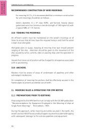
formation from toe to heel <strong>with</strong>out proper control over theplacement process. In the past, several stimulation treatmentsin dual lateral wells have not achieved the objective ofincreasing production in spite of placing acid in both laterals— raising doubts about the effectiveness of the diversion orthe placement of the fluids.During the stimulation job <strong>with</strong> conventional CT, there areseveral uncertainties proving that there is no control on the job:• Where are the thief zones?• Are these thief zones hydrocarbon bearing or not?• Where in the hole is the acid squeezed? Is it at the CTbottom-hole assembly (BHA) nozzle depth?• Does it matter where the CT end is positioned whilespotting the treatment fluids?• In the case of additional bullheading, will fluid go to theCT BHA nozzle depth, even if there is a thief zone atthe heel?• Is squeeze pressure below or above frac pressure?• What is the downhole temperature during treatment?• When should the pump diverter be used? Where? Whatvolume should be pumped?• Is the diverter working? Is the next acid stage wasted tothe same thief zone?• What type of diversion fluid should be pumped into nonhydrocarbonbearing and hydrocarbon bearing zones?• Do we have an adequate pumping sequence? Should itbe the same for all wells?• Are the fluid volumes enough or too little?• Is there an understanding of the injection profiles?The availability of open hole logs helps in identifying theintervals <strong>with</strong> a higher probability of production. It is possiblethat one lateral holds a very good quality zone thatpredominates over the other, becoming a key target of thestimulation treatment.If one lateral contains predominantly higher permeabilityand porosity sections, it is also certain that most of the fluidvolume has the tendency to go towards this section. In this case,it is likely that the damage is not removed and potentialproduction in the other lateral is not unlocked. It would then beideal to have a means to understand if this situation is takingplace. Many of these questions can be addressed <strong>with</strong> real-timedownhole measurements taken as the CT treatment progresses.Ultimately, the objective of the stimulation treatment in gaswells <strong>with</strong> open hole completions in Ghawar field includes:• Ensure uniform placement of acid into the targetedreservoir intervals.• Ensure efficient diversion to stimulate the targeted zones.• Avoid treating the same lateral twice.A case study of utilizing the latest CT advancements, in twodual lateral horizontal open hole gas producers, thatdemonstrates how to optimize a stimulation treatment as itdevelops, is described in this article. Using an innovativeworkflow — interpretation of distributed temperature survey(DTS) responses, correlated <strong>with</strong> reservoir data — it is possibleto selectively place treatment fluids, maximizing the contact ofstimulation fluids <strong>with</strong> the targeted formation sections.BACKGROUNDWell A was completed as a dual lateral <strong>Khuff</strong>-C gas wellproducer. The well was completed <strong>with</strong> a 4½” tubing string.The well is cased <strong>with</strong> a 7” liner to the top of the producingreservoir at 11,623 ft measured depth (MD). The motherbore(L0) was then drilled successfully to a TD of 13,895 ft MD.After that, the lateral (L1) was drilled, <strong>with</strong> a junction at11,652 ft MD, to 15,331 ft MD. After drilling, the well wasflowed back for cleanup but was not flowing. It was decidedto stimulate the well, targeting as the main priority the L1section between 12,500 ft and 13,100 ft.Well B was completed as a dual lateral <strong>Khuff</strong>-C gas wellproducer. The well was completed <strong>with</strong> a 4½” tubing string.The well is cased <strong>with</strong> a 7” liner to the top of the producingreservoir at 11,471 ft MD. The motherbore (L1) was thendrilled successfully to a TD of 14,858 ft MD (lower lateral).After that, lateral L2 (upper lateral) was drilled after openinga window in the 7” liner at 11,477 ft MD to 11,488 ft MD to14,625 ft MD. The well production was very poor. A decisionto stimulate the two laterals was taken, Fig. 1.TVD (ft)TVD (ft)11200.0011250.0011300.0011350.0011400.0011450.0011500.0011550.0011600.0011650.0011700.0011200.0011250.00L1: Pilot holeL2: Lateral11300.0011350.0011400.0011450.0011500.0011550.0011600.0011650.0011700.000 1000 2000 3000 4000 5000V-Section (ft)Fig. 1. Well A and B trajectories.0 1000 2000 3000 4000 5000V-Section (ft)24 SUMMER 2010 SAUDI ARAMCO JOURNAL OF TECHNOLOGY
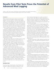
Fig. 2. ACTive fiber optics.DESCRIPTION OF FIBER OPTIC ENABLED COILEDTUBING (FOECT) TECHNOLOGYOptical fibers are widely used in communication due to thebenefits they offer for data transmission. In an application tooil field services, a system based on fiber optics has beendeveloped and adapted for use in CT operations, to enabledownhole measurements in real time.FOECT system features include:• Fiber Optic Carrier (FOC) inside the CT string• The FOECT BHA• Surface acquisition• DTS system• Interpretation servicesThe downhole tool includes a CT head that terminates thefiber optical connections; the electronic package that housesthe downhole communication system; the battery, the sensorsfor internal and external pressure and temperature; and theCasing Collar Locator (CCL). The tool is flow through andmade of acid and H 2 S resistant materials.The FOC, that has an outside diameter of 1.8 mm(0.071”), is previously installed in the CT string. The FOC isnon-intrusive; therefore standard operations normally done<strong>with</strong> conventional strings can be carried out, includingpumping corrosive fluids and dropping balls, Fig 2.On the surface, the downhole data is transmitted from theCT working reel, via wireless and <strong>with</strong>out a collector, into theCT Control Cabin, where specialized software is used toacquire, display, monitor and record the parameters of the jobin real time. The surface acquisition system also has the abilityto communicate <strong>with</strong> the tool downhole to send commands.API format printouts of the operation parameters can bedelivered in the field.As the fiber itself acts as a temperature sensor across thelength of the CT string, a DTS monitoring system can alsobe used to capture reliable, accurate and real-time downholedistributed temperature profiles, along <strong>with</strong> data acqui -sition, analysis, and interpretation. There is no need forcalibration points along the fiber or for calibrating the fiberprior to installation in the wellbore. The system enablesmonitoring thermal profiles of injection at different timesduring the treatment.To provide greater system integration — an interpretationspecialist <strong>with</strong> reservoir production background andmeasurements expertise — identifies the downhole events andperforms an analysis of the combined data <strong>with</strong> specializedsoftware; to adjust the treatment, as many times as needed.The interpretation specialist, who can be on the well site or inthe office, interacts <strong>with</strong> the stimulation and CT engineers, aswell as the well engineers, to decide the next steps.MULTILATERAL SELECTIVE REENTRY TOOL (MSRT)The BHA used in the intervention also included theMultilateral Selective Reentry Tool (MSRT), which consists ofa surface-controlled orienting tool and a controllable bent sub.The system identifies the window of the selected lateral beforeattempting reentry, and confirmation of successful identificationand entry is visible at surface through a softwaredisplayedpressure log. The corrosion-resistant reentry tool isoperated solely on flow and is conveyed <strong>with</strong> standard CTequipment.The MSRT profiles the lateral junction during the upwardpasses, Fig. 3, instead of rotating a full cycle at a specifieddepth, which is the technique for standard access tools. TheFig. 3. Multilateral selective re-entry tool operational sequence.SAUDI ARAMCO JOURNAL OF TECHNOLOGY SUMMER 2010 25
orientation of the bent sub relative to the lateral window ischanged <strong>with</strong> the orienting tool, indexing 12 times to cover360°. Even if the tool cannot be oriented, because the bentsub is locked in a washout, the upward movement of thewand allows the tool to flip in the desired orientation after thefirst few inches of movement.DESCRIPTION OF THE STIMULATION CAMPAIGN —APPLICATION OF FLUIDS, EQUIPMENT ANDPROCESSESTwo <strong>Khuff</strong> gas wells were treated <strong>with</strong> selective fluidplacement based on DTS data. The treatment objective ofWell A was to selectively enter the upper lateral —characterized by the best pay — for acid stimulation toenhance well production. Once a fluid injection profile wouldbe established in the targeted lateral, an optimized stimulationtreatment based on interpretation of the real time downholedata provided by the FOECT would be executed andevaluated for efficiency. The treatment objective of Well B wasa similar optimized stimulation of hydrocarbon bearing pay inboth horizontal open hole laterals. Each well would be treated<strong>with</strong> a fluid placement schedule, open for modification basedon the well response to the treatment as observed andinterpreted on-site by an interpretation specialist. Real timedata from the FOECT system recorded during or after keystages of each treatment provided the downhole measurementsnecessary for interpretation of downhole events.The general procedure for optimized FOECT carbonateacid stimulation consists of the following stages:• Preflush injection. Warm back analysis, identification ofpotential thief zones.• Acid diagnostic stage. Heat buildup analysis, identificationof potential thief zones, fluid placementschedule.• Acid treatment stage 1. Diversion analysis: Remedialcorrections to fluid placement schedule.• Acid treatment stage 2. Diversion analysis: Furthercorrections to fluid placement schedule as required.• Post flush injection. Warm back analysis: <strong>Fluid</strong>distribution confirmation and treatment evaluation.Additional customized stages may be added as needed toaid interpretation and understanding of key downhole eventsor to record and document developments to the fluid injectionprofile during treatment. The detailed stimulation summary ofWell A highlights the potential importance of this interactiveapproach to optimize the treatment, Fig 4.Well A - First run in hole (RIH):• CT was RIH from the surface. Break circulation wasmaintained <strong>with</strong> treated water.• CT stopped at 12,412 ft to record the geothermalgradient baseline.• FOECT data used for lateral confirmation (CT in targetlateral L1).• Treatment fluids prepared for stimulation of main targetpay in lateral L1.Well A - Preflush injection in lateral L1:• Starting from 12,445 ft, CT was RIH to 13,000 ft, thenpulled out of hole (POOH) to 12,500 ft.• Preflush (125 bbl) was pumped while reciprocatingthe coil.• FOECT data analysis showed significant lossesoccurring to lateral L0 at the lateral junction.• Decision was made to pump an undiverted initial acidstage to remove potential skin damage.Well A - First acid stage in lateral L1:• CT was POOH from 13,000 ft - 12,600 ft whilepumping acid, then RIH to 13,000 ft.• Treatment acid: 26% HCl acid (200 bbl).• FOECT data analysis showed continued losses to lateralL0 <strong>with</strong> little or no acid going to the formation in L1.• Decision was made to focus on diversion from lateralL0 <strong>with</strong>out exiting lateral L1. L0 Log is showing 50 ftclose to the heel <strong>with</strong> double gas saturation comparedto other gas bearing zones in L0 and L1.Well A - Foam and viscoelastic self-diverting acid to divertfrom lateral L0 while maintaining CT inside lateral L1:• CT pulled to 12,000 ft to pump foamed and viscoelasticself-diverting acid to lateral L0 (CT still 300 ft insidelateral L1).• Diverter: 20 bbl foam and 10 bbl viscoelastic selfdivertingacid pumped nitrified to lateral L0.Well A - Second acid stage in lateral L1:• CT was reciprocated from 13,000 ft - 12,600 ft whilepumping acid, then RIH 13,100 ft for analysis.Fig. 4. Well completion for Well A.26 SUMMER 2010 SAUDI ARAMCO JOURNAL OF TECHNOLOGY
• Treatment acid: 26% HCl acid (150 bbl).• FEOCT data analysis showed reduced losses to lateralL0 and increased acid effects in the target lateral L1 inan interval extending 200 ft above the expected targetpay (12,400 ft - 12,700 ft) <strong>with</strong> little acid effect across300 ft of the pay.• Decision was made to pump nitrified viscoelastic selfdivertingacid, prior to a final acid stage targeting theunder-stimulated 300 ft of the main pay <strong>with</strong> stationaryacid injection in three stages.Well A - Placement of nitrified viscoelastic self-diverting acidin L1 before final acid stage:• CT was POOH from 13,000 ft - 12,400 ft while placingdiverter, then RIH to 13,000 ft prior to final acid stage.• Diverter: 200 bbl nitrified viscoelastic self-divertingacid.Well A - Final L1 acid stage:• CT was POOH from 13,000 ft - 12,600 ft, stopping atkey targets at 12,900 ft, 12,800 ft and 12,750 ft in themain pay.• Treatment acid: 26% HCl acid (250 bbl). Ten bbl acidwas pumped stationary at each of the three target points.• FEOCT analysis showed further increased acid effectsacross the 12,400 ft - 13,000 ft interval, covering theentire main pay and extending 200 ft above it.• Decision was made to pump post flush while POOH toprofile for lateral L0 entry <strong>with</strong> the MSRT.Well A - Stimulation of lateral L0:• Several attempts were made to access lateral L0 afterprofiling the open hole junction <strong>with</strong> the MSRT. Despitemany attempts, the MSRT did not allow access to lateralL0, suggesting washout of the open hole junction beyondwhat was expected during the job design. Consistentlosses throughout the acid treatment of lateral L1 mayhave contributed to deteriorate the condition of the openhole junction prior to MSRT profiling.• Decision was made to pump the treatment <strong>with</strong> CTstationary 100 ft above the lateral junction. To avoid restimulatinglateral L1, the decision was taken to fill upthis lateral (13,000 ft - 12,000 ft) <strong>with</strong> foam.• The treatment targeting L0 was pumped stationary at11,600 ft:- Nitrified preflush (50 bbl).- Five stages of nitrified 15% HCl viscoelastic selfdivertingacid (50 bbl each) followed by nitrified26% HCl acid (100 bbl each).- Post flush (120 bbl).This concluded the treatment of Well A. FOECT DTS datafrom key stages of the stimulation treatment is included inAppendix A Fig. 1.Fig. 5. Well completion for Well B.Following is the detailed stimulation summary of Well B,Fig 5:Well B - First RIH – natural pass confirmation (targetinglateral L2):• CT was RIH from surface. Break circulation maintained<strong>with</strong> treated water.• CT stopped at 11,800 ft for lateral confirmation <strong>with</strong>FOECT data (400 ft below lateral window).• FOECT data gave positive indication that, CT naturalpass was the non-target lateral L1.• Decision was made to profile the window <strong>with</strong> MSRTto enter lateral L2.Well B - MSRT profiling for lateral L2:• CT was reciprocated across the lateral window toacquire the MSRT profile. Once established, CT wasRIH attempting access to lateral L2.• CT stopped at 11,800 ft for lateral confirmation <strong>with</strong>FOECT data (400 ft below lateral window).• FOECT data gave positive indication that CT was againin the nontarget lateral L1.• Decision was made to re-profile the window <strong>with</strong>MSRT to enter lateral L2.Well B - MSRT re-profiling for lateral L2:• CT was reciprocated across the lateral window toreacquire the MSRT profile. Once established, CT wasRIH attempting access to lateral L2.• CT stopped at 11,800 ft for lateral confirmation <strong>with</strong>FOECT data (400 ft below lateral window).• FOECT data gave positive indication that CT was in thetarget lateral L2.• CT was run beyond L1 TD confirming that CT isindeed in L2.• Decision was made to perform a clean out of lateral L2(a 2 7 ⁄8” high-pressure jetting tool was used), tag TD fora secondary lateral confirmation and inject preflushacross the lateral L2 open hole.SAUDI ARAMCO JOURNAL OF TECHNOLOGY SUMMER 2010 27
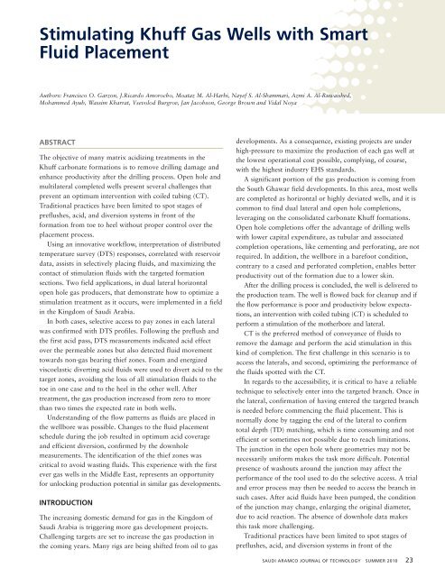
Well B - Preflush injection lateral L2:• Preflush was pumped while RIH to TD.• FOECT data analysis showed three potential thief zonesat 12,300 ft -12,480 ft, 12,740 ft - 12,800 ft and12,900 ft - 13,000 ft. No losses were observed to occurat the lateral window.• Decision was made to target the potential thief zones<strong>with</strong> nitrified 26% viscoelastic self-diverting acid whilePOOH and injecting 26% viscoelastic self-diverting acidacross the other target zones while RIH.Well B - Diversion and acid stages in lateral L2 (500 bbl of26% viscoelastic self-diverting acid):• CT was POOH from 14,800 ft - 11,550 ft, then RIH to14,800 ft.• Diverter: nitrified viscoelastic self-diverting acid pumpedacross the thief zones while POOH.• Treatment acid: 26% viscoelastic self-diverting acidpumped across the target zones while RIH to TD.• FOECT data analysis showed good diversion in theintervals 12,300 ft - 12,480 ft and 12,900 ft - 13,000 ft,but continued fluid loss to the interval 12,740 ft -12,800 ft. No losses at lateral window.• Decision was made to re-target the remaining potentialthief zone <strong>with</strong> diversion, prior to a final acid stagetargeting the main pay <strong>with</strong> stationary acid injection atthree selected points, followed by post flush injectedacross the entire open hole section of lateral L2.Well B - Post flush injection profile in lateral L2:• CT was RIH from 11,550 ft - 14,800 ft (TD).• Post flush was pumped while RIH.• FOECT analysis showed an almost uniform injectionprofile <strong>with</strong> residual diversion still in effect across theinterval 12,740 ft - 12,800 ft. No losses at lateral window.• Decision was made to proceed to POOH to the lateralwindow and enter the CT natural pass lateral L1 forstimulation.Well B - Natural pass confirmation (targeting lateral L1):• CT was pulled above the lateral window, then RIHattempting access to lateral L1.• CT stopped at 11,800 ft for lateral confirmation <strong>with</strong>FOECT data (400 ft below lateral window).• FOECT data gave positive indication that CT was in thetarget lateral L1.• Decision was made to perform a clean out of lateral L1,tag TD for a secondary lateral confirmation and injectpreflush across the lateral L1 open hole.Well B - Preflush injection lateral L1:• Preflush was pumped while RIH to TD.• FOECT data analysis showed no potential thief zones inthe lateral pay. Indication of fluid loss to the toe is noticed.• Decision was made to pump foam across 13,900 ft -13,800 ft to prevent downhole fluid loss. Then 26%viscoelastic self-diverting acid will be pumped across thetarget zone.Well B - Diversion and acid stages in lateral L1 (250 bbl of26% viscoelastic self-diverting acid):• Diverter: foam pumped across 13,900 ft - 13,800 ft.• Treatment acid: 26% HCl viscoelastic self-diverting acidpumped while RIH across target zone 12,660 ft -13,630 ft.• FOECT data suggested good diversion of the foam asno downhole fluid loss could be observed. An eventemperature distribution further suggested that uniformfluid distribution was achieved.• Decision was made to proceed <strong>with</strong> the final post flushstage.Well B - Post flush injection profile in lateral L1:• Post flush was pumped while RIH to end of target zone.• FOECT analysis indicated a near uniform injectionprofile. No losses were observed at the lateral window.• Decision was made to proceed <strong>with</strong> nitrogen kick-offand final POOH.This concluded the treatment of Well B.RESULTSSuccessful stimulation of target zones in both Well A and Bwas achieved <strong>with</strong> optimized smart fluid placement. Uniformacid coverage across the target zones was achieved bymonitoring fluid placement, and diverting <strong>with</strong> the requiredvolumes of nitrified viscoelastic self-diverting acid across theidentified thief zones. Significant improvements to the fluidinjection profile were observed after treatment.In Well A, excessive loss of treatment fluids to the non-keylateral L0 was avoided by the early identification of laterallosses and subsequent mitigation <strong>with</strong> foam and nitrifiedviscoelastic self-diverting acid diversion techniques. Confir -mation of gradually reduced losses to the thief zone in lateralL0 was observed.In Well B, early lateral identification prevented the need fortagging TD, which saved time and CT pipe cycling. Completeloss of all stimulation fluids to the toe was avoided by earlyidentification of the thief zone and subsequent mitigation <strong>with</strong>foam diversion techniques.Based on offset wells and the type of completion, initialproduction expectations for <strong>Wells</strong> 1 and 2 were 12 MMscf/day and 10 MMscf/day, respectively. For Well 1, poststimulationproduction increased 92% above expectations to23 MMscf/day. For Well 2, post-stimulation productionincreased 140% above expectations to 24 MMscf/day, Fig. 6.28 SUMMER 2010 SAUDI ARAMCO JOURNAL OF TECHNOLOGY
2520151050Well 1 Well 2Production before StimProduction Expected by ClientProduction after Stim• Real time adjustment of pumping schedule (fluid typeand volume) based on DTS response.• Stop thinking that CT is a diversion means as treatmentfluids will be squeezed into thief zones even <strong>with</strong> the useof high-pressure jetting tools (fluids can even travel backto a different lateral looking for the less resistant path).• Stop pumping predetermined stages of acid and diverterfrom toe to heel <strong>with</strong>out any real time monitoring offluids placement and diverter efficiency.Well production beyond expectation was achieved thanksto the smart fluid placement.ACKNOWLEDGMENTSThe authors thank <strong>Saudi</strong> <strong>Aramco</strong> and Schlumbergermanagement for permission to publish and present this article.REFERENCESFig. 6. Post-stimulation production.CONCLUSIONSFOECT DTSs were used during matrix acidizing of two bilateralhorizontal gas wells to optimize acid coverage and wellproductivity.Cleanout and stimulation of each wellbore was facilitated<strong>with</strong> a 2 7 ⁄8” high-pressure jetting tool. Lateral access andlateral confirmation was enabled by the use of the MSRT andreal time DTS measurements.In each well, placement of the main treating fluid wasmodified real time based on the temperature responseobserved <strong>with</strong> DTS profiles. Treatment fluid loss to the lateralwindow/junction or to the toe could be confirmed <strong>with</strong>downhole measurements and controlled <strong>with</strong> real timemodifications of the treatment fluid pumping schedule. DTSprofiles, after each of the modified acid treatment stages,indicated significant incremental improvements towardsuniform fluid placement, compared to the pre-stimulationpreflush injection profiles. Post flush evaluation in each lateralfurther confirmed diversion efficiency of the chemical diverter.Downhole FOECT data supported by real timeinterpretation during key stages of the treatment resolved theuncertainties associated <strong>with</strong> conventional acid stimulation ofmultilateral open hole carbonate wells, and enabled propercontrol of CT stimulation jobs. Optimum acid coverage oftarget zones can be achieved through the following:• Identification of accessed lateral.• Identification of gas/non-gas bearing thief zones beforeand during stimulation, which will assist us in decidingthe type and volume of diverter when required to pumpit. Identification of fluids placement and diversionefficiency.1. Al-Zain, A., Duarte, J., Haldar, S., et al.: “SuccessfulUtilization of Fiber Optic Telemetry Enabled Coiled Tubingfor Water Shut-off on a Horizontal Oil Well in GhawarField,” SPE paper 126063, presented at the SPE <strong>Saudi</strong>Arabia Section Technical Symposium and Exhibition,al-Khobar, <strong>Saudi</strong> Arabia, May 9-11, 2009.2. Wortmann, H., Peixoto, L.P., Leising, L., Bunaes, C. andNees, E.: “Selective Coiled Tubing Access to allMultilaterals Adds Wellbore Construction Options,” SPEpaper 74491, presented at the IADC/SPE DrillingConference, Dallas, Texas, February 26-28, 2002.3. Al-Buali, M., Al-Arnaout, I., Al-Shehri, A., Halder, S. andAl-Driweesh, S.: “Case History: Successful Application ofCombined Rotary-Jetting and MLT to Stimulate DualLateral Producer in Ghawar Field,” SPE paper 119675,presented at the SPE Middle East Oil & <strong>Gas</strong> Show andConference, Bahrain International Exhibition Centre,Manama, Bahrain, March 15-18, 2009.4. Parta, P.E., Parapat, A., Burgos, R., et al.: “A SuccessfulApplication of Fiber Optic Enabled Coiled Tubing <strong>with</strong>Distributed Temperature Sensing (DTS) Along <strong>with</strong>Pressures to Diagnose Production Decline in an OffshoreOil Well,” SPE paper 121696-MS, presented at theSPE/ICoTA Coiled Tubing & Well Intervention Conferenceand Exhibition, The Woodlands, Texas, March 31 - April1, 2009.5. Hadley, M.R., Brown, G.A. and Naldrett, G.: “EvaluatingPermanently Installed Fiber Optic Distributed TemperatureMeasurements Using Temperature Step Resolution,” SPEpaper 97677, presented at the SPE International ImprovedOil Recovery Conference, Asia Pacific, Kuala Lumpur,Malaysia, December 5-6, 2005.6. Hadley, M.R. and Kimish, R.: “Distributed TemperatureSensor Measures Temperature Resolution in Real Time,”SAUDI ARAMCO JOURNAL OF TECHNOLOGY SUMMER 2010 29
SPE paper 116665, presented at the SPE Annual TechnicalConference and Exhibition, Denver, Colorado, September21-24, 2008.7. Smith, R.C. and Steffensen, R.J.: “Interpretation ofTemperature Profiles in Water Injection <strong>Wells</strong>,” SPE paper4649, presented at the SPE-AIME 48 th Annual Fall Meeting,Las Vegas, Nevada, September 30 - October 3, 1973.APPENDIX A – SUPPORTING FIGURES AND FOECTINTERPRETATION EXAMPLESIn treatment of the two candidate wells, the targeted upperlateral of Well A was selectively entered by use of the MSRT,and the CT was RIH for stimulation of the hydrocarbonbearing pay zone. While RIH a geothermal temperatureprofile was recorded (Fig. A1, green temperature curve) toNitrified chemical diverterFoamed water8/10/2009 11:44 p.m. Preflush8/10/2009 5:08 a.m. Lateral Confirmation8/11/2009 6:30 a.m. 1st Acid8/11/2009 5:13 p.m. Acid and Diverter8/12/2009 5:56 a.m. Acid JettingEOL at 11,624 ftLateral Junction at 11,710 ftFig. A1. Well A, L1 FOECT data from key treatment stages.Fig. A2. Well B, L1 FOECT data providing lateral confirmation.30 SUMMER 2010 SAUDI ARAMCO JOURNAL OF TECHNOLOGY
Fig. A3. Post flush temperature response (green) highlighting diversion effects obtained as compared to the preflush injection profile (blue) in Well B, lateral L1.establish a lateral junction baseline dataset for interpretationof the following recorded data. Reaching TD, preflush wasinjected and squeezed to formation through the CT whilereciprocating once across the open hole. The warm backFOECT data following the preflush injection is highlighted inFig. A1 in light blue.Interpretation of the FOECT preflush warm back data,suggests that significant losses occur to the non-targetedlateral L2, indicated <strong>with</strong> an orange line on Fig. A1. As fluidsare pumped through CT in a well, a combination ofconvection heating of the pumped treatment fluids andconvection cool-down of the surrounding wellbore by thepassing of the colder fluids pumped from surface takes place.In cases where the fluid pumped is lost to a zone above theCT nozzle, the combination of convection heating of the fluidand convection cool-down of the wellbore typically results ina step change in temperature across a zone or a lateraljunction to which significant fluid loss occurs. In Well A,lateral L1, the pumped preflush is being heated throughconvection both while being pumped through the CT andwhile traveling up hole in the L1 CT-wellbore annulustowards the lateral junction of lateral L2. The effect on DTSprofile data of the losses of heated injected fluid to thejunction is a significant step change from the convectioncooled wellbore above the lateral junction to the heated fluidentering the lateral junction from below. Identifying suchlosses early in the treatment allows for immediate remedialactions to be taken, to reduce the volumes pumped and lost toother laterals.In Well B, both laterals were to be stimulated, but themeasured TD of the two laterals (L1 and L2) was less than 250ft apart, Fig. A2. An early lateral confirmation was in this caseachieved <strong>with</strong> the FOECT by running 400 ft into the naturalpass lateral. Recording FOECT data while surface injecting 40bbl treated water to the CT-wellbore annulus provided a smallbut measurable cool-down across the wellbore. With the CT inthe main bore, the 4½” tailpipe acted as severe downhole flowrestriction preventing fluid flow (and the associated cool-down)below the tailpipe. Figure A3 shows the FOECT temperaturedata recorded before, during and after surface injection, givingan early positive lateral confirmation 400 ft into the lateral. Astwo attempts were required for positive confirmation of entryto the desired L2 lateral, this early warning avoided the needfor three full trips to tag TD for lateral confirmation, saving atotal of 8,800 running ft in the operation.Overlaid against the preflush injection profile in blue, Fig.A3 shows the post flush temperature profile in solid green. Bycomparing the pre- and post flush profiles, the diversionefficiency of the pumped may be evaluated. A near uniformtemperature trend is now observed across the treated open holesection stimulation of lateral L1 in Well B. This suggests that amore uniform injection profile across the targeted pay has beenachieved through diversion during the stimulation treatment.Another important observation is the lack of anyobservable temperature anomalies across the lateral windowto the main bore. This confirms that the treatment fluidspumped to stimulate the target lateral were not lost throughthe lateral window.SAUDI ARAMCO JOURNAL OF TECHNOLOGY SUMMER 2010 31
BIOGRAPHIESFrancisco O. Garzon joined <strong>Saudi</strong><strong>Aramco</strong> in 2005. He currently worksas a Lead Engineer in the Hawiyahunit. Including his time <strong>with</strong> <strong>Saudi</strong><strong>Aramco</strong>, Francisco has more than 20years of experience in the oil industry,working for Oxy, Schlumberger andBP. His expertise includes petroleum engineering and wellinterventions, well performance optimization usingopen/cased logs, production history, NODAL and pressuretransient analysis information, coiled tubing andstimulation operations (chemical and hydraulic fracturing),workover interventions and artificial lift optimization.Francisco received his B.S. degree in PetroleumEngineering from the Universidad de America, Bogotá,Colombia in 1984 and his M.S. degree in PetroleumEngineering from Heriot-Watt University, Edinburgh,Scotland in 1991.J. Ricardo Amorocho is a SeniorPetroleum Engineer consultant <strong>with</strong>the Hawiyah Engineering Unit in the<strong>Gas</strong> Production Engineering Division(GPED) in ‘Udhailiyah. His worksupports coiled tubing operations,e-Line stimulation and well workintervention. Ricardo has 16 years of diversified oilindustry work, of which 10 years were <strong>with</strong> BP working invarious assignments, mainly in Colombia on wellintervention on CT, CTD and stimulation.Since joining <strong>Saudi</strong> <strong>Aramco</strong> in 2006, Ricardo has beeninvolved in a wide variety of well intervention activities<strong>with</strong> special emphasis on coiled tubing operations,horizontal well cleanouts and stimulation, and fishingoperations.Ricardo received his B.S. degree in PetroleumEngineering in 1993 from the Fundacion Universidad deAmerica in Bogota, Colombia.Moataz M. Al-Harbi is a <strong>Gas</strong>Production Engineer assigned to theHaradh Engineering Unit in the <strong>Gas</strong>Production Engineering Division(GPED) in ‘Udhailiyah. He has 13years of diversified oil industryexperience.In 1996 Moataz received his B.S. degree in MechanicalEngineering from King Fahd University of Petroleum andMinerals (KFUPM), Dhahran, <strong>Saudi</strong> Arabia. Aftergraduation, he joined Schlumberger where he specialized instimulation operations. Moataz then joined <strong>Saudi</strong> <strong>Aramco</strong>in 2004, and is currently participating in the ProductionEngineering Specialist Program (PESP) as a Stimulation andFracturing specialist candidate. He has been activelyinvolved in the successful implementation of a number ofnew technologies aimed at enhancing well productivity, andis a mentor to young <strong>Saudi</strong> engineers.Nayef S. Al-Shammari joined <strong>Saudi</strong><strong>Aramco</strong> in 1995 as a ProductionEngineer. He worked in differentorganizations (one year as ReservoirEngineer and two years as WellServices and Completion Engineer).Nayef has headed the <strong>Gas</strong> WellServices & Completion Division, South Ghawar WellServices Division, North Ghawar Well Services Division,Khurais and Central Arabia Well Services Division, ABQQProduction Engineering Division, <strong>Gas</strong> ProductionEngineering Division and the HRDH <strong>Gas</strong> ProductionEngineering Unit. He is currently a Supervisor in the <strong>Gas</strong>Production Engineering Division covering AinDar,‘Uthmaniyah and Shedgum’s Production EngineeringDivision.Nayef received his B.S. degree in Petroleum Engineeringin 1995 from King Fahd University of Petroleum andMinerals (KFUPM), Dhahran, <strong>Saudi</strong> Arabia.Azmi A. Al-Ruwaished is a ProductionEngineering assistant Superintendentin the Southern Area ProductionServices Department (SAPSD), wherehe is involved in gas productionservices, well completion andstimulation activities. He is mainlyinterested in the field of production engineering, productionoptimization and new well completion applications.Azmi has been working <strong>with</strong> <strong>Saudi</strong> <strong>Aramco</strong> for the past15 years in areas related to production engineering and gascompletion operations.In 2000, Azmi received his B.S. degree in PetroleumEngineering from Louisiana State University (LSU), BatonRouge, LA.He is member of the Society of Petroleum Engineers(SPE).Mohammad Ayub is currently working<strong>with</strong> the Planning Unit as a Supervisor.He joined <strong>Saudi</strong> <strong>Aramco</strong> in 1982 andhas held various positions in theSouthern Area Production EngineeringDepartment (SAPED) and theSouthern Area Production ServicesDepartment (SAPSD).Mohammad received his B.S. degree in Petroleum and<strong>Gas</strong> Engineering from the University of Engineering andTechnology, Lahore, Pakistan.He is member of the Society of Petroleum Engineers(SPE).32 SUMMER 2010 SAUDI ARAMCO JOURNAL OF TECHNOLOGY
Wassim Kharrat has been working<strong>with</strong> Schlumberger since September1998 in several countries around theworld, including Tunisia, Germany,Libya, the United States and <strong>Saudi</strong>Arabia. He built his technical andoperational expertise in coiled tubingand matrix stimulation. Currently, Wassim is working as aCoiled Tubing District Technical Engineer in ‘Udhailiyah<strong>with</strong> a focus on introducing and implementing ACTive newtechnology (real-time monitoring <strong>with</strong> fiber optic) for alltypes of coiled tubing jobs.In 1998, he received his M.S. degree in Mechanical andIndustrial Engineering from École Nationale Supérieured'Arts et Métiers (ENSAM), France.Vsevolod Bugrov received his M.S.degree in Petroleum Engineering in2003 from the Russian State Universityof Oil and <strong>Gas</strong>, Moscow, Russia. Aftergraduation he started his career <strong>with</strong>Schlumberger as a Coiled TubingEngineer.He has 6 years of experience in well intervention andstimulation services, including various applications ofcoiled tubing in arctic and desert conditions. Currently, heworks in ‘Udhailiyah providing technical support for theSouthern Area Production Engineering Department(SAPED) Coiled Tubing operations.Jan Jacobsen is the ACTive DomainChampion for Schlumberger in theMiddle East. He joined Schlumbergeras a Coiled Tubing Field Engineer in2004, working in Germany and TheNetherlands. In 2007 Jan joinedSchlumberger Data Consulting Servicesfor assignments in the U.K. and France. He then joinedSchlumberger Well Services and Data Consulting Services inhis current position in <strong>Saudi</strong> Arabia in 2009.In 2004, Jan received his M.S. degree in CivilEngineering from the Technical University of Denmark,Copenhagen, Denmark, specializing in applied geophysics.George Brown joined Sensa in March1999 as the Manager of InterpretationDevelopment and is currentlySchlumberger’s TemperatureInterpretation Advisor. (Sensa wasbought by Schlumberger in 2001). Heis responsible for developing theinterpretation methodology and software to facilitate theanalysis of Schlumberger’s permanent and interventiondeployed distributed temperature measurements and hasbeen analyzing distributed temperature data since 1999.Before Sensa, George spent 15 years <strong>with</strong> BPExploration where he was Head of the Petrophysics groupat the Sunbury Research Center and later Senior FormationEvaluation Consultant working <strong>with</strong> BP’s “Intelligent<strong>Wells</strong>” team charged <strong>with</strong> developing new permanentmonitoring systems for horizontal and sub-sea wells, whichincluded the early trials and evaluation of fiber optictemperature measurements.Prior to BP, he spent 12 years <strong>with</strong> SchlumbergerWireline working in both the Middle East (<strong>Saudi</strong> Arabia,Dubai and Turkey) and the North Sea area (Aberdeen andNorway) in a variety of operational and managementpositions.George holds a first class honors degree in MechanicalEngineering, has published over 20 technical papers, beenawarded several patents and was a Society of Petroleum ofEngineers’ (SPE) Distinguished Lecturer during 2004/5.Vidal Noya is a Coiled Tubing ServicesTechnical Manager assigned to theregion of <strong>Saudi</strong> Arabia, Kuwait andBahrain. He has 19 years of experiencein the oil field services. Since joiningSchlumberger, he has worked in severalprojects related to operations andtechnology in the area of well intervention and production.Vidal’s experience includes assignments in South America,North Africa, the Middle East and Europe.He received his B.S. degree in Mechanical Engineering in1991 from the Universidad Central de Venezuela, Caracas,Venezuela.SAUDI ARAMCO JOURNAL OF TECHNOLOGY SUMMER 2010 33