Selected Analytical Methods for Well and Aquifer Evaluation
Selected Analytical Methods for Well and Aquifer Evaluation
Selected Analytical Methods for Well and Aquifer Evaluation

You also want an ePaper? Increase the reach of your titles
YUMPU automatically turns print PDFs into web optimized ePapers that Google loves.
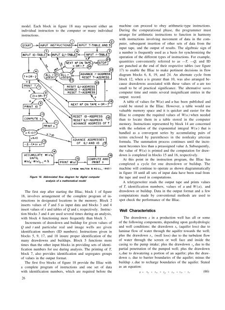
model. Each block in figure 18 may represent either anindividual instruction to the computer or many individualinstructions.Figure 18. Abbreviated flow diagram <strong>for</strong> digital computeranalysis of a mathematical modelThe first step after starting the Illiac, block 1 of figure18, involves arrangement of the complete program of instructionsin designated locations in the memory. Block 2inserts values of T <strong>and</strong> S as input data <strong>and</strong> blocks 3 <strong>and</strong> 4insert values of r <strong>and</strong> tables of Q <strong>and</strong> t, respectively. Instructionblocks 3 <strong>and</strong> 4 are used several times during an analysis,with block 4 functioning more frequently than block 3.Increments of drawdown <strong>and</strong> buildup <strong>for</strong> given values ofQ <strong>and</strong> t <strong>and</strong> particular real <strong>and</strong> image wells are givenidentification numbers (ID numbers). Instructions given inblocks 5, 9, 17, <strong>and</strong> 18 insure proper identification of themany drawdowns <strong>and</strong> buildups. Block 5 functions moretimes than the other input blocks in providing sets of identificationnumbers <strong>for</strong> use during analysis. The printing of T,block 7, also provides identification <strong>and</strong> segregates groupsof values in the output <strong>for</strong>mat.The first five blocks of figure 18 provide the Illiac witha complete program of instructions <strong>and</strong> one set of datawith identification numbers, which are required be<strong>for</strong>e the26machine can proceed to obey arithmetic-type instructions.During the computational phase, the programmer mustarrange <strong>for</strong> arithmetic instructions to function in harmonywith instructions involving movement of data in the computer,subsequent insertion of other sets of data from theinput tape, <strong>and</strong> the output of results. The algebraic sign ofa number is frequently used as a basis <strong>for</strong> synchronizing theoperation of the different types of instructions. For example,quantities conveniently referred to as —T, —Q, <strong>and</strong> IDare punched at the end of their respective tables (see figure17) to enable the Illiac to make pertinent decisions in flowdiagram blocks 6, 8, 19, <strong>and</strong> 24. An alternate cycle fromblock 12, when u is greater than 10, was also arranged becausedrawdowns associated with these values of u are toosmall to be of practical significance. The alternative savescomputer time <strong>and</strong> omits several insignificant entries in theoutput record.A table of values <strong>for</strong> W(u) <strong>and</strong> u has been published <strong>and</strong>could be stored in the Illiac. However, a table would usevaluable memory space <strong>and</strong> it is quicker <strong>and</strong> easier <strong>for</strong> theIlliac to compute the required values of W(u ) when neededthan to locate them in a table stored in the computermemory. Instructions represented by block 14 are concernedwith the solution of the exponential integral W(u ) that ish<strong>and</strong>led as a convergent series by accumulating pairs ofterms enclosed by parentheses in the nonleaky artesian<strong>for</strong>mula. The summation process continues until the incrementbecomes less than a preassigned value ∆. Subsequently,the value of W(u) is printed <strong>and</strong> the computation <strong>for</strong> drawdownis completed in blocks 15 <strong>and</strong> 16, respectively.At this point in the instruction program, the Illiac hascompleted a cycle <strong>for</strong> one drawdown or buildup. Themachine will continue to operate as shown diagrammaticallyin figure 18 until all sets of input data have been read fromthe tape <strong>and</strong> used in computations.A teletypewriter reads the output tape <strong>and</strong> prints valuesof T, identification numbers, values of u <strong>and</strong> W ( u), <strong>and</strong>drawdown or buildup. Data in the output <strong>for</strong>mat <strong>and</strong> a fewcomputations made by conventional methods are used tospot check the per<strong>for</strong>mance of the Illiac.<strong>Well</strong> CharacteristicsThe drawdown s in a production well has all or someof the following components, depending upon geohydrologic<strong>and</strong> well conditions: the drawdown s a (aquifer loss) due tolaminar flow of water through the aquifer towards the well;plus the drawdown s w (well loss) due to the turbulent flowof water through the screen or well face <strong>and</strong> inside thecasing to the pump intake; plus the drawdown S p due to thepartial penetration of the pumped well; plus the drawdowns d due to dewatering a portion of an aquifer; plus the drawdowns b due to barrier boundaries of the aquifer; minus thebuildup s r due to recharge boundaries of the aquifer. Statedas an equation:S = S a + S w + S p + S a + S b — S r(66)