GPM500 Generator Protection Module - SAM Electronics GmbH
GPM500 Generator Protection Module - SAM Electronics GmbH
GPM500 Generator Protection Module - SAM Electronics GmbH

You also want an ePaper? Increase the reach of your titles
YUMPU automatically turns print PDFs into web optimized ePapers that Google loves.
<strong>GPM500</strong><br />
<strong>Generator</strong> <strong>Protection</strong> <strong>Module</strong>
2<br />
<strong>Generator</strong> <strong>Protection</strong> <strong>Module</strong> <strong>GPM500</strong><br />
The microprocessor based <strong>Generator</strong><br />
<strong>Protection</strong> System <strong>GPM500</strong> performs<br />
the protection and control of medium<br />
and low voltage generators and networks.<br />
The <strong>GPM500</strong> can be operated<br />
as stand alone or in combination with<br />
other <strong>GPM500</strong> communicating via data<br />
bus. Generally each application (e.g.<br />
generator, coupling circuit breaker, etc.)<br />
requires an own <strong>GPM500</strong> for the<br />
protection.<br />
The <strong>GPM500</strong> is mainly intended for the<br />
protection and control of the following<br />
listed applications:<br />
■ Diesel generators<br />
■ Shaft generators<br />
■ Emergency generators<br />
■ Coupling circuit breakers<br />
■ Transfer line circuit breakers<br />
■ Transformers<br />
■ Motors<br />
■ Shore connections<br />
■ Filters<br />
■ HR grounding<br />
Typically the <strong>GPM500</strong> is fitted inside the<br />
associated panel of the switch board.<br />
The modular design allows the extension<br />
of functions and of in- and outputs<br />
in an easy way. Via connection plugs the<br />
modules can be directly interconnected.<br />
The installation of the modules can be<br />
easily done via snap-on rails.<br />
Besides the below listed protection and<br />
control functions of the <strong>GPM500</strong> data<br />
transfer with external monitoring and<br />
control systems is possible via an interface<br />
(Modbus, CANopen) and with the<br />
Internet (Modbus/ TCP). The authorisation<br />
for remote access/modification of<br />
parameters can be restricted.<br />
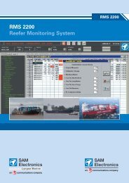
For operation, setting of parameters and<br />
control of the <strong>GPM500</strong> a separate<br />
tableau with touch screen display is<br />
used (BAT500). Several graphical symbols<br />
on the main picture and all relevant<br />
data such as current, voltage, load etc.<br />
allow general survey of the status of<br />
e.g. the generator and the respective<br />
generator circuit breaker. Control and<br />
modification (password protected) of<br />
parameters can be done on protection<br />
function based pages (e.g. one page<br />
for overcurrent protection with all relevant<br />
parameters). An alarm list will<br />
appear automatically in case of failure.<br />
An integrated PLC allows the programming<br />
of additional protection and control<br />
functions. The programming of the<br />
PLC can be done with functional blocks<br />
according to IEC 1131 on a PC in an<br />
easy and user friendly way. Via the<br />
touch screen display BAT500 the online<br />
visualisation of PLC process functions<br />
and variables is possible.
<strong>Generator</strong> <strong>Protection</strong> <strong>Module</strong> <strong>GPM500</strong><br />
<strong>Protection</strong> Functions<br />
■ Instantaneous overcurrent protection<br />
(short circuit) – (ANSI Code No. 50)<br />
■ Thermal overload (overcurrent)<br />
– (ANSI Code No. 49)<br />
■ Reverse power<br />
– (ANSI Code No. 32)<br />
■ Under-/ Overvoltage<br />
– (ANSI Code No. 27 / 59)<br />
■ Under-/ Overfrequency<br />
– (ANSI Code No. 81L / 81H)<br />
■ Phase balance (asymmetry) current<br />
protection – (ANSI Code No. 46)<br />
■ Monitoring of excitation<br />
– (ANSI Code No. 24 & 40)<br />
■ Circuit breaker failure<br />
– (ANSI Code No. 50BF)<br />
■ Undercurrent monitoring (underload)<br />
– (ANSI Code No. 37)<br />
■ Synchronising<br />
– (ANSI Code No. 25)<br />
■ Phase failure<br />
– (ANSI Code No. 47)<br />
■ Stator protection<br />
■ Load shedding (switch off of<br />
unimportant consumers)<br />
■ Voltage backup for undervoltage coil<br />
■ <strong>Protection</strong> against earthfault<br />
(optional) – (ANSI Code No. 50G)<br />
■ Differential protection (optional)<br />
– (ANSI Code No. 87G/M/N/T)<br />
■ Neutral voltage displacement<br />
(optional) – (ANSI Code No. 59N/64)<br />
Power Management<br />
Functions<br />
■ Automatic synchronising<br />
■ Active load sharing<br />
■ Asymmetrical load sharing<br />
(e.g. for shaft generators)<br />
■ Frequency control<br />
■ "Topload" function<br />
■ Blackout start<br />
Options<br />
■ Load dependig diesel start / stop<br />
■ Load control of big consumer<br />
(e.g. Bowthruster)<br />
■ Expandable with Diesel <strong>Protection</strong><br />
<strong>Module</strong> DPM500<br />
■ Data transfer to external monitoring<br />
and controlsystems<br />
3
Technical Data<br />
Mechanical Data<br />
Mounting rail modules with 16 respectively<br />
32 terminals (by 4 pole plug<br />
connectors with a code profile) and a<br />
12 pole plug connection to the next<br />
modules. The 12 pole plug connection<br />
contains the internal CAN bus, the<br />
external CAN bus for the connection<br />
of the BAT500 and contacts for the<br />
control voltage supply. The SLE500<br />
divides the internal bus into the ZK bus<br />
(on the left) and the analog bus (on<br />
the right). The ZK bus is used for<br />
communication purposes between the<br />
individual assemblies via CAN and is<br />
managed by the ZKG500. The analog<br />
bus serves to acquire analog values<br />
(currents and voltages) of TRV500 and<br />
DIF500 assemblies.<br />
■ Assemblies for mounting onto DIN<br />
EN mounting rails (top hat rails)<br />
- Dimensions (W x H x D):<br />
45 x 100 x 115 mm – (NEG510,<br />
SLE500, DIF500, USS500)<br />
22,5 x 100 x 115 mm – (NEG500,<br />
ZKG500, DIO500, DCC500,<br />
GOV500, TRV500/501/502)<br />
In the basic configuration (for LVgenerator<br />
application with check<br />
synchroniser/ without synchronising)<br />
the modules have following width:<br />
- 157,5 mm – (NEG500, ZKG500,<br />
2xDIO500, SLE500, TRV500)<br />
■ Touch panel for door mounting<br />
- Dimensions (W x H x D):<br />
187 x 147 x 70 mm<br />
<strong>Protection</strong> degree IP20 (front of touch<br />
panel IP65)<br />
Ambient temperature (during operation):<br />
0°C ... 55°C acc. various classification<br />
societys for mounting in switchboard<br />
panels<br />
Electrical Data<br />
■ Required power supply DC 24 V<br />
(18-32 V) with a ripple < 5 % and/or<br />
a 3 phase power supply AC 19 V/<br />
40-72 Hz (redundant supply) e.g.<br />
generator voltage (via transformer)<br />
■ Direct measurement of voltages for<br />
rated voltages up to 450 V<br />
■ Direct measurement of currents for<br />
rated currents up to 1 A<br />
■ Load of relay outputs AC 230 V/4 A<br />
respectively DC 24 V/4 A<br />
(DIO500 only 24 V/4 A)<br />
■ Electronic analogue outputs ± 10 V,<br />
0..20 mA or 4..20 mA<br />
■ Power consumption of the modules<br />
up to 48 W (BAT500: 14,4 W)<br />
Interfaces<br />
■ 3 external CAN interfaces with up to<br />
1 Mbit/s (support CANopen)<br />
■ RS485 interface with up to 56 kBit/s<br />
(<strong>SAM</strong>-protocol, Modbus: Master<br />
and Slave)<br />
<strong>SAM</strong> <strong>Electronics</strong> <strong>GmbH</strong><br />
Energy and Drives<br />
Behringstrasse 120<br />
22763 Hamburg . Germany<br />
■ RS232 interface for maintenance<br />
and software down-/upload. For<br />
remote maintenance and the soft<br />
ware down-/upload an Ethernet<br />
coupler can be connected.<br />
Software<br />
■ Parameters of protection functions<br />
can be modified via the touch<br />
screen display.<br />
■ Same basic software with all protection<br />
functions in all configurations/<br />
applications. The necessary protection<br />
functions and the respective<br />
basic picture on the BAT500 will be<br />
activated / deactivated by parameters<br />
according to the preselection of<br />
application (e.g. generator or<br />
transformer).<br />
■ User software: The programmable<br />
logic controller (PLC) of the ZKG500<br />
can be graphically programmed on a<br />
PC (with function blocks) according<br />
IEC1131.<br />
Phone: +49 - (0)40 - 88 25 - 26 20<br />
Fax: +49 - (0)40 - 88 25 - 41 02<br />
Energy-Drives-Sales@sam-electronics.de<br />
www.sam-electronics.de<br />
Printed in Germany · Technical alterations reserved · © <strong>SAM</strong> <strong>Electronics</strong> <strong>GmbH</strong> · DS 1.073.07/2006