High Efficiency Multiple Screw Pumps
High Efficiency Multiple Screw Pumps
High Efficiency Multiple Screw Pumps

Create successful ePaper yourself
Turn your PDF publications into a flip-book with our unique Google optimized e-Paper software.
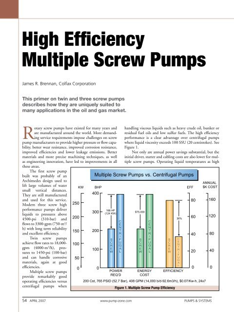
<strong>High</strong> <strong>Efficiency</strong><strong>Multiple</strong> <strong>Screw</strong> <strong>Pumps</strong>James R. Brennan, Colfax CorporationThis primer on twin and three screw pumpsdescribes how they are uniquely suited tomany applications in the oil and gas market.Rotary screw pumps have existed for many years andare manufactured around the world. More demandingservice requirements impose challenges on screwpump manufacturers to provide higher pressure or flow capability,better wear resistance, improved corrosion resistance,improved efficiencies and lower leakage emissions. Bettermaterials and more precise machining techniques, as wellas engineering innovation, have led to improvements in allthese areas.The first screw pumpbuilt was probably of anArchimedes design used tolift large volumes of watersmall vertical distances.They are still manufacturedand used for this service.Modern three screw highperformance pumps deliverliquids to pressures above4500-psi (310-bar) andflows to 3300-gpm (750-m 3 /h) with long term reliabilityand excellent efficiency.Twin screw pumpsachieve flow rates to 18,000-gpm (4000-m 3 /h), pressuresto 1450-psi (100-bar)and can handle corrosivematerials, again at goodefficiencies.<strong>Multiple</strong> screw pumpsprovide remarkably goodoperating efficiencies versuscentrifugal pumps whenhandling viscous liquids such as heavy crude oil, bunker orresidual fuel oils and low sulfur fuels. The high efficiencyperformance is a clear advantage over centrifugal pumpswhere liquid viscosity exceeds 100 SSU (20 centistokes). SeeFigure 1.Not only are annual power savings substantial, but theinitial driver, starter and cabling costs are also lower for multiplescrew pumps. Operating liquid temperatures as highFigure 1. <strong>Multiple</strong> <strong>Screw</strong> Pump <strong>Efficiency</strong>54 April 2007 www.pump-zone.com <strong>Pumps</strong> & Systems
Figure 2. A ROSE ® process 600-deg F twin screw pump.as 600-deg F (315-deg C) have been achieved in twin screwpumps for the ROSE ® deasphalting process (see Figure 2).Timing gears and bearings are force cooled while the pumpbody is jacketed for a hot oil circulating system to bring thepump to process temperature in a gradual, controlled manner.Three screw pumps have been applied to the same elevatedtemperature, more commonly on asphalt or vacuum tower bottomsservices in refineries.To quote Dushyant Mehra, research analyst with Frost &Sullivan, “The primary challenge for oil & gas pump manufacturersis to improve the energy costs and efficiency of theirpumps.” 1 The pump user can also contribute to their bottomline by using the most efficient technology to move liquidproducts. Many times this is a positive displacement pump, notFigure 2A. A typical multiple screw pump performance curve.a centrifugal pump. Figure 2A shows excellent efficiency over abroad range of discharge pressures.In multiple screw pumps, each wrap of screw thread effectivelyforms a stage of pressure capability. <strong>High</strong> pressure pumpshave 5 to 12 stages, or wraps, whereas low pressure pumps mayhave only 2 or 3 wraps. This staged pressure capability is illustratedin Figure 3. More wraps are incorporated into pumpsdesigned for higher pressure service.Figure 3 (above left). Staging effects of screw pumps.Figure 3A (left). A diesel driven three screw pump on a heavy crude pipeline in Central America.Figure 3B (above). A heavy crude three screw pump on pipeline service in Western Canada.<strong>Pumps</strong> & Systems www.pump-zone.com April 2007 55
Fifty years makes for a golden anniversary.That’s how long it is since 1957, when Flygt US opened for businessin Hoosick Falls, New York. Of course, even then we were far fromstrangers to engineering excellence. Our parent company in Sweden,ITT Flygt AB, set it all in motion back in 1901.From the beginning, Flygt US has been all about innovation.We were first to develop submersible pumps for municipalities andindustry. Our initial concentration on wastewater and dewateringpumps subsequently expanded into component manufacturing, totalpackaged solutions and much more. Today our N-Pump technologymakes clogging a thing of the past.Meanwhile, we’re still growing, building a strong and diversecompany that is dedicated to producing the highest quality pumps,mixers and monitoring and control systems. Just as important, ourservice and support keep customers up and running and satisfied.Today, millions of ITT Flygt pumps are on the job throughoutAmerica and worldwide, and we’re grateful for the long lasting andintimate relationships we have with our customers as well as theirongoing confidence in us. It’s a pleasure to serve all of you, and ourcommitment toward meeting your needs remains ironclad.We’re proud of the first fifty years of Flygt US.But wait ‘til you see what’s next!circle 100 on card or go to psfreeinfo.com
Three <strong>Screw</strong> <strong>Pumps</strong>:Principle ApplicationsThree screw pumps are the largest classof multiple screw pumps in service today.Typical applications include machinerylubrication, hydraulic elevators, fuel oiltransport, fuel oil burner service, powerhydraulics and refinery processes, such ashigh temperature viscous products includingasphalt, vacuum tower bottoms andresidual fuel oils.Three screw pumps also find extensiveuse in crude oil pipeline service (see Figure3A), as well as gathering, boosting and loading of barges andships. These pumps are also used for high pressure distillate fuelinjection for gas turbines.Designs are now available in sealless configurations, suchas magnetic drives and canned arrangements, to allow customersto reduce emissions and meet government guidelines. Threescrew pumps are renowned for their low noise levels, high reliability,ease of repair and long life (see Figure 3B).Figure 5. A power rotor with balance piston.Figure 4. Single and double suction three screw pumps.Design and OperationThree screw pumps are manufactured in two basic styles, singlesuction and double suction (see Figure 4). The single suctiondesign is used for low to medium flow rates and low to veryhigh pressure. The double suction design is really two pumpsin parallel in one casing, used for medium to high flow rates atlow to medium pressure.Three screw pumps generally have only one mechanicalshaft seal and one, or perhaps two, bearings that locate the shaftaxially. Internal hydraulic balance is such that axial and radialhydraulic forces are opposed and cancel each other. Thus, bearingloads are very low.Another common characteristic of three screw pumpsis that all but the smallest, low pressure designs incorporatereplaceable liners in which the pumping screws rotate. Minorrepair kits (seals, gaskets, bearing) and major repair kits (allwearing parts, including those in the minor repair kit) alloweasy field repair of most three screw pumps. So field repair is asimple matter and the piping does not have to be disturbed.The center screw, called the power rotor, performs all thepumping. The meshed outside screws, called idler rotors, causeeach liquid-holding chamber to be separated from the adjacentone, except for running clearances. This effectively allows stagingof the pump pressure rise. Because the center screw is performingall the pumping work, the drive torque transferred tothe idler rotors is only necessary to overcome viscous drag of thecylindrical rotor spinning within its liner clearance.The theoretical flow rate of these pumps is a function ofspeed, screw set diameter and the lead angle of the threads.Basically, flow rate is a function of the cube of the center screwdiameter. Slip flow is the volumetric inefficiency due to clearances,differential pressure and viscosity. It is a function of thesquare of the power rotor diameter, resulting in larger pumpsbeing inherently more efficient than smaller pumps. In crudeoil pipeline service, the power savings is greatest compared tocentrifugal pumps.Speed is ultimately limited by the applications/systemcapability to deliver flow to the pump inlet at a sufficient pressureto avoid cavitation. This is true of all pumps. Three screwpumps tend to be high speed pumps, not unlike centrifugalpumps. Two pole and four pole motors are most commonlyused.Slower speed may be necessary when dictated by largeflows, very high viscosities or low available inlet pressures. <strong>High</strong>speed operation is desirable when handling low viscosity liquidssince the idler rotors generate a hydrodynamic liquid film intheir load zones that resists radial hydraulic loads, very similarto hydrodynamic sleeve bearings found in turbomachinery.To achieve the highest pressure capability from three screwpumps, it is necessary to control the shape of the screws whileunder hydraulic load. Five-axis NC profile grinding accomplishesthis best, through complete dimensional control and ahigh degree of repeatability. Opposed loading of the idler rotoroutside diameters on the power rotor root diameter dictate thatthese surfaces be heat treated to withstand the cyclic stress.Again, profile thread grinding produces thefinal screw contour while leaving the rotors quitehard, in the order of 58R C . This hard surface betterresists abrasive wear from contaminants and extendsthe service life.Because some three screw pump applicationsrange to pressures of 4500-psi (310-bar), pumpingelement loading due to hydrostatic pressure can bequite high. With hydraulic balance, the forces are58 April 2007 www.pump-zone.com <strong>Pumps</strong> & Systems
The Performance Leader inSealing TechnologyFigure 6. Idler rotor hydraulic balance.balanced in two planes such that bearingloads are minimal to increase operatinglife.Single ended pumps use two similarbut different techniques to accomplishaxial hydraulic balance. The centerscrew, or power rotor, incorporates abalancing piston at the discharge end ofthe screw thread (see Figure 5). The areaof the piston is made about equal to thearea of power rotor thread exposed todischarge pressure.Consequently, equal opposingforces produce zero net axial force due todischarge pressure and place the powerrotor in tension. The balance pistonrotates within a close clearance stationarybushing, which may be hardened or hardcoated to resist erosive wear. The driveshaft side of the piston is normally internallyor externally ported to the pumpinlet chamber. Balance leakage flowacross this running clearance flushes thepump mechanical seal, which remains atnominal pump inlet pressure.The two outer screws, idler rotors,also have their discharge ends exposedto discharge pressure. Through variousarrangements, discharge pressureis introduced into a hydrostatic pocketarea at the inlet end of the idler rotors(see Figure 6).The effective area is just slightlyless than the exposed discharge end area,resulting in approximately equal opposingaxial forces on the idler rotors. Theidler rotors are therefore in compression.Should any force cause the idler rotorMechanical SealsTotalSealCare Supply SystemsU.S. & WorldwideService CentersSeal RepairInventory ManagementTrainingVisit us at Booth 10202 (Stadium) at theOffshore Technology ConferenceApril 30 – May 3, HoustonEagleBurgmann Industries LP10035 Brookriver DriveHouston, TX 77040Tel: 800-303-7735Fax: 713-939-9091www.eagleburgmann.comcircle 118 on card or go to psfreeinfo.com<strong>Pumps</strong> & Systems www.pump-zone.com April 2007 59
to move toward discharge, a resulting loss of pressure acting on the cup shoulderarea or hydrostatic land area tends to restore the idler rotor to its design runningposition.The upper view in Figure 6 shows a stationary thrust block (cross hatched) anda stationary, radially self locating balance cup. Discharge pressure is brought intothe cup via internal passages within the pump or rotor itself. The lower view showsa hydrostatic pocket machined into the end face of the idler rotor. It, too, is fedFigure 7. Radial hydraulic balance in threescrew pumps.with discharge pressure. The gap shownis exaggerated and is actually only a fewthousandths of an inch.For some contaminated liquid services,the hydrostatic end faces of theidler rotors are gas nitride hardened ormanufactured from solid tungsten carbideand shrink fitted to the inlet end ofthe idler rotors. When the cup design isused, the cup inside diameter and shoulderarea are normally gas nitride hardened.Both techniques are used to resistwear due to the fine contaminants.In a radial direction, three screwpumps achieve power rotor hydraulicbalance due to symmetry. Equal pressureacting in all directions within a stage orwrap results in no radial hydraulic forcessince there are no unbalanced areas. Thepower rotor frequently has a ball bearingto limit end float for proper mechanicalseal operation, but it is otherwise undernegligible load. Idler rotor radial balanceis accomplished through the generationof a hydrodynamic liquid film, in thesame fashion as a journal or sleeve bearing(see Figure 7).The eccentricity of the rotatingidler rotors sweeps liquid into a convergingclearance, resulting in a pressurizedliquid film. The film pressure acts on theidler rotor outside diameters in a directionopposing the hydraulically generatedradial load (see diagonally opposingarrows indicating direction of loading).Increasing viscosity causes morefluid to be dragged into the pressurizedfilm, causing the film thickness and thuscircle 136 on card or go to psfreeinfo.com60 April 2007 www.pump-zone.com <strong>Pumps</strong> & Systems