RA Balancing propeller shaft - Ad Kusters
RA Balancing propeller shaft - Ad Kusters
RA Balancing propeller shaft - Ad Kusters

Create successful ePaper yourself
Turn your PDF publications into a flip-book with our unique Google optimized e-Paper software.
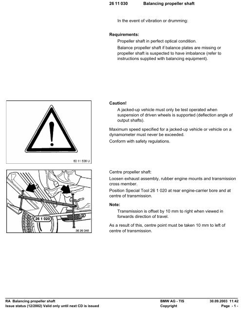
26 11 030 <strong>Balancing</strong> <strong>propeller</strong> <strong>shaft</strong>In the event of vibration or drumming:Requirements:Propeller <strong>shaft</strong> in perfect optical condition.Balance <strong>propeller</strong> <strong>shaft</strong> if balance plates are missing or<strong>propeller</strong> <strong>shaft</strong> is suspected to have imbalance (refer toinstructions supplied with balancing equipment).Caution!A jacked-up vehicle must only be test operated whensuspension of driven wheels is supported (deflection angle ofoutput <strong>shaft</strong>s).Maximum speed specified for a jacked-up vehicle or vehicle on adynamometer must never be exceeded.Conform with safety regulations.Centre <strong>propeller</strong> <strong>shaft</strong>:Loosen exhaust assembly, rubber engine mounts and transmissioncross member.Position Special Tool 26 1 020 at rear engine-carrier bore and atcentre of transmission.Note:Transmission is offset by 10 mm to right when viewed inforwards direction of travel.As a result of this, centre point must be taken 10 mm to left ofcentre of transmission.<strong>RA</strong> <strong>Balancing</strong> <strong>propeller</strong> <strong>shaft</strong> BMW AG - TIS 30.09.2003 11:42Issue status (12/2002) Valid only until next CD is issued Copyright Page - 1 -
Determine measuring point on transmission.Transmission S 5 D 200/250 G:Measure 10 mm to left from cast rib (1) on transmission housing.Mark measuring point (2) and apply Special Tool 26 1 020.Transmission S 5 D 310 Z:Note:Cast rib (1) on transmission housing is offset 7 mm fromcentre.Measure 3 mm to left of cast rib (1) on transmission housing.Mark measuring point (2) and apply Special Tool 26 1 020.Automatic transmission A 5 S 310 Z:Measure 10 mm to left of centre transmission-extension mountingbolt (1).Mark measuring point (2) and apply Special Tool 26 1 020.Automatic transmission A 4 S 310/270 R:Determine measuring point.Measure from centre of bore towards inside.A = 31 mmMark measuring point.Starting from centre of transmission, measure 10 mm to left, markand attach Special Tool 26 1 020.<strong>RA</strong> <strong>Balancing</strong> <strong>propeller</strong> <strong>shaft</strong> BMW AG - TIS 30.09.2003 11:42Issue status (12/2002) Valid only until next CD is issued Copyright Page - 2 -
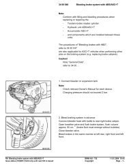
Move transmission sidewards until special-tool gauge has equaldistances on left and right sides.Secure crossmember.Tightening torque, refer to Technical Data 24 71 1AZChecking/adjusting <strong>propeller</strong> <strong>shaft</strong>-deflection angle:Remove exhaust assembly,refer to Group 18.Unscrew heat-protection plate at centre and right front.M40 engine:Secure rail (steel ruler) on belt pulley in vertical position (use aclamp).Place gauge 26 1 030 on rail.M50/M51 engine:Secure rail (steel ruler) on vibration damper in vertical position (usea clamp).Place gauge 26 1 030 on rail.Set needle perpendicular with help of bubble level.Read degrees.Note:Always fit measuring gauge with scale pointing in samedirection (e.g. scale on right).One graduation = 5'.Position of vehicle is not important as only individual angle iscompared.<strong>RA</strong> <strong>Balancing</strong> <strong>propeller</strong> <strong>shaft</strong> BMW AG - TIS 30.09.2003 11:42Issue status (12/2002) Valid only until next CD is issued Copyright Page - 3 -
Hold gauge 26 1 030 against front section of <strong>propeller</strong> <strong>shaft</strong> andmeasure angle.Determine deflection angle of joint disk,(refer to Technical Data)and, if necessary, correct on transmission suspension or centremount by installing shims (up to max. 3 mm).This requires supporting transmission and unscrewingcrossmember from body.Example:Engine angle 2° 16'Propeller-<strong>shaft</strong> angle 2° 06'Joint-disk deflection angle 0° 10'Note:When correcting a deflection angle by installing shims,remember that deflection angles of adjacent joints will alsochange.In general, deflection angles of joints should be as small aspossible.<strong>RA</strong> <strong>Balancing</strong> <strong>propeller</strong> <strong>shaft</strong> BMW AG - TIS 30.09.2003 11:42Issue status (12/2002) Valid only until next CD is issued Copyright Page - 4 -
Place Special Tool 26 1 030 on machined surface of final drive atbottom.Determine deflection angle,refer to Technical Data.Apply Special Tool 26 1 030 on rear section of <strong>propeller</strong> <strong>shaft</strong> andmeasure angle.Determine deflection angle of centre mount,(refer to Technical Data)and, if necessary, correct on transmission suspension or centremount by installing shims (up to max. 3 mm).<strong>RA</strong> <strong>Balancing</strong> <strong>propeller</strong> <strong>shaft</strong> BMW AG - TIS 30.09.2003 11:42Issue status (12/2002) Valid only until next CD is issued Copyright Page - 5 -