Installation Manual - LG HVAC VRF Systems
Installation Manual - LG HVAC VRF Systems
Installation Manual - LG HVAC VRF Systems

Create successful ePaper yourself
Turn your PDF publications into a flip-book with our unique Google optimized e-Paper software.
TABLE OF CONTENTSSafety Precautions ......................................................................................................................................................................................................4-5<strong>Installation</strong> ....................................................................................................................................................................................................................4Wiring ...........................................................................................................................................................................................................................5Operation ......................................................................................................................................................................................................................5Specifications ..............................................................................................................................................................................................................6-8ZLABKA01A Low Ambient Baffle Kit for 6-ton Multi V III Outdoor Units 6ZLABKA02A Low Ambient Baffle Kit for 8, 10, and 12-Ton Multi V III Outdoor Units 7PRVC1 Control Kit ........................................................................................................................................................................................................8Dimensions ................................................................................................................................................................................................................9-15ZLABKA01A Top Discharge Elbow For 6-ton Units ......................................................................................................................................................9ZLABKA01A Side Wind Baffles For 6-ton Units .........................................................................................................................................................10ZLABKA01A Rear Wind Baffle For 6-ton Units ........................................................................................................................................................... 11ZLABKA02A Left Top Discharge Elbow For 8-12 Ton Units .................................................................................................................................................12ZLABKA02A Right Top Discharge Elbow For 8-12 Ton Units..........................................................................................................................................................13ZLABKA02A Side Wind Baffles For 8-12 Ton Units ....................................................................................................................................................14ZLABKA02A Rear Wind Baffle For 8-12 Ton Units .....................................................................................................................................................15Wiring Diagrams ......................................................................................................................................................................................................16-17Multi V III Heat Pump Outdoor Unit & PRVC1 Control Kit ...........................................................................................................................................16Multi V III Heat Recovery Outdoor Unit & PRVC1 Control Kit ...........................................................................................................................................17Product <strong>Installation</strong> .................................................................................................................................................................................................18-20Attaching the Low Ambient Cooling Kit Top Discharge Elbow ..........................................................................................................................................18Attaching the Low Ambient Cooling Kit Side Wind Baffles ..........................................................................................................................................19Attaching the Low Ambient Cooling Kit Rear Wind Baffle ..........................................................................................................................................20Electrical Wiring <strong>Installation</strong> ..................................................................................................................................................................................21-30Installing the PRVC1 Control Kit in the Outdoor Unit Frames ......................................................................................................................................21-30Precommissioning ..................................................................................................................................................................................................31-32Dip Switch Settings on the PRVC1 Control Kit PCB...................................................................................................................................................31Dip Switch Settings on the Heat Pump ODU Main PCB ............................................................................................................................................32Dip Switch Settings on the Heat Recovery ODU Main PCB ..........................................................................................................................................32Sequence of LED / Operations ....................................................................................................................................................................................33Sequence of LEDs ......................................................................................................................................................................................................33Sequence of Operations .............................................................................................................................................................................................33Due to our policy of continuous product innovation, some specifications may change without notification.<strong>LG</strong> Electronics U.S.A., Inc., Englewood Cliffs, NJ. All rights reserved. “<strong>LG</strong> Life’s Good” is a registered trademark of <strong>LG</strong> Corp. 3
SAFETY PRECAUTIONSThe instructions below must be followed to prevent product malfunction, property damage, injury or death to the user or other people.Incorrect operation due to ignoring any instructions will cause harm or damage. The level of seriousness is classified by the symbolsdescribed below." "This symbol indicates that the action or lack thereof could possibly cause death or personal injury." "This symbol indicates that the action or lack thereof could possibly cause property damage.MULTI V Low Ambient Cooling Kit <strong>Installation</strong> <strong>Manual</strong>" " Note:" "This symbol indicates that the action or lack thereof could possibly cause equipment malfunction or failure.This symbol indicates that the following action should not be performed.INSTALLATIONAll electric work must be performed by a licensed electricianand conform to local building codes or, in the absence oflocal codes, with the National Electrical Code, and theinstructions given in this manual.If the power source capacity is inadequate or the electric work is notperformed properly, it may result in fire, electric shock, physical injury ordeath.Do not install, remove, or re-install the unit by yourself(customer).There is risk of fire, electric shock, explosion, physical injury or death.Ask the dealer or an authorized technician to install the unit.Improper installation by the user may result in water leakage, fire, electricshock, physical injury or death.For re-installation of an installed unit, always contact thedealer or an authorized service provider.There is risk of fire, electric shock, explosion, and physical injury or death.Be very careful when transporting the product.• One person should not carry the product.• Some products use polypropylene bands for packaging. Do not usepolypropylene bands as a means of transportation.Dispose the packing materials safely.• Packing materials, such as nails and other metal or wooden parts,may cause puncture wounds or other injuries.• Tear apart and throw away plastic packaging bags so that childrenmay not play with them and risk suffocation and death.Install the unit in such a way as to prepare for any possiblestrong winds or earthquakes.Improper installation may cause the unit to fall over, resulting in physicalinjury or death.Do not touch the sharp edges of the unit during installation.There is a risk of personal injury.Do not store or use flammable gas or combustibles near theunit.There is risk of product failure, fire, and physical injury or death.Securely install the control box and panel covers.If the cover and panel are not installed securely, dust or water may enterthe outdoor unit, causing fire, electric shock, and physical injury or death.Install the low ambient control kit in the specified location.There is risk of product failure, fire, and physical injury or death.4Due to our policy of continuous product innovation, some specifications may change without notification.<strong>LG</strong> Electronics U.S.A., Inc., Englewood Cliffs, NJ. All rights reserved. “<strong>LG</strong> Life’s Good” is a registered trademark of <strong>LG</strong> Corp.
SAFETY PRECAUTIONSWIRINGThe information contained in this manual is intended for useby a qualified, experienced service technician familiar withsafety procedures and who is equipped with the proper toolsand test instruments.Failure to carefully read and follow all instructions in this manual canresult in equipment malfunction, property damage, personal injury or death.Highly dangerous electrical voltages are used in this system;refer to the diagrams and these instructions when wiring.Improper connections and inadequate grounding can cause accidentalinjury or death.Only a qualified electrician should wire this system.Electrical shock can cause physical injury or death.Do not touch the printed circuit board (PCB) when the poweris connected.There is risk of fire, electric shock, explosion, physical injury or death.Note:Refer to local, state, and federal codes, and use power wiresof sufficient current capacity and rating.Wires that are too small may generate heat and cause a fire.Secure all field wiring connections with the appropriate strainrelief so that outside forces on the cables will not affect theterminals.Inadequate connections may generate heat, cause a fire and physicalinjury or death.Connect all wiring tightly.Loose wiring may overheat at connection points, causing a fire, physicalinjury or death.Turn the power off at the main power box before opening theunit to check or repair electrical parts and wiring.Electrical shock can cause physical injury or death.Do not supply power to the unit until all wiring and piping installation are completed or reconnected and checked.Product DataOPERATIONDo not use unspecified power wiring or damage the powerwiring.There is risk of fire, electric shock, physical injury or death.Do not operate the unit with the panels or guards removed;keep fingers and clothing away from any moving parts.The rotating, hot, or high-voltage parts of the unit can cause physicalinjury or death.Do not permit water to enter the unit.There is risk of unit failure, fire, electric shock, physical injury or death.If the unit becomes flooded or submerged, contact anauthorized service provider.There is risk of fire, electric shock, physical injury or death.Note:Do not block the inlet or outlet.It may cause product malfunction.Due to our policy of continuous product innovation, some specifications may change without notification.<strong>LG</strong> Electronics U.S.A., Inc., Englewood Cliffs, NJ. All rights reserved. “<strong>LG</strong> Life’s Good” is a registered trademark of <strong>LG</strong> Corp.5
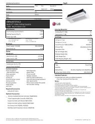
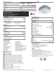
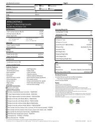
SPECIFICATIONSZLABKA01A Low Ambient Cooling KitFor 6-ton Multi V III Outdoor UnitsMULTI V Low Ambient Cooling Kit <strong>Installation</strong> <strong>Manual</strong>Compatible Outdoor Units:ARUN072BT3 / ARUN072DT3ARUB072BT3 / ARUB072DT3Note:Low Ambient Cooling Kit cannot be used with triple-frame systems.Standard Features:• Allows operation down to -4°F in cooling mode, and down to 14°Fin synchronous mode (Heat Recovery Outdoor Units only).• Damper operator has spring return, normally open actuator.Color:Warm GrayMaterial:20 Gauge Sheet MetalFigure 1: ZLABKA01A Low Ambient Cooling Kit for 6-Ton Multi V III Outdoor Units.Each Kit Includes:• Right wind baffle.• Left wind baffle.• Rear wind baffle.• Top discharge elbow with motorized damper and 24V damperactuator.• (50) #10 x 1/2" self-drilling hex-head screws.• Sealtite connector (for routing of actuator control and power wiringdown to outdoor unit electrical box).Required Accessories (sold separately):Control Kit - PRVC1.Front ViewSide View6Due to our policy of continuous product innovation, some specifications may change without notification.<strong>LG</strong> Electronics U.S.A., Inc., Englewood Cliffs, NJ. All rights reserved. “<strong>LG</strong> Life’s Good” is a registered trademark of <strong>LG</strong> Corp.
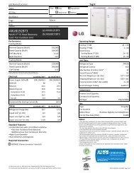
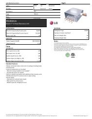
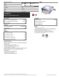
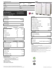
Product DataSPECIFICATIONSZLABKA02A Low Ambient Cooling KitFor 8, 10, and 12-Ton Multi V III Outdoor UnitsCompatible Outdoor Units:ARUN096BT3 / ARUB096BT3ARUN121BT3 / ARUB121BT3ARUN144BT3 / ARUB144BT3ARUN096DT3 / ARUB096DT3ARUN121DT3 / ARUB121DT3ARUN144DT3 / ARUB144DT3Note:Low Ambient Cooling Kit cannot be used with triple-frame systems.Standard Features:• Allows operation down to -4°F in cooling mode, and down to 14°Fin synchronous mode (Heat Recovery Outdoor Units only).• Damper operator has spring return, normally open actuator.Each Kit Includes:• Right wind baffle.• Left wind baffle.• Rear wind baffle.• Top discharge elbow with motorized damper and 24V damperactuator (Elbow includes left and right components that which mustbe connected together before installing on the outdoor unit.)• (50) #10 x 1/2" self-drilling hex-head screws.• Sealtite connector (for routing of actuator control and power wiringdown to outdoor unit electrical box).Color:Warm GrayMaterial:20 Gauge Sheet MetalRequired Accessories (sold separately):Control Kit - PRVC1.Figure 2: ZLABKA02A Low Ambient Cooling Kit for 8, 10, and 12-Ton Multi V III Outdoor Units.Front ViewSide ViewDue to our policy of continuous product innovation, some specifications may change without notification.<strong>LG</strong> Electronics U.S.A., Inc., Englewood Cliffs, NJ. All rights reserved. “<strong>LG</strong> Life’s Good” is a registered trademark of <strong>LG</strong> Corp.7
SPECIFICATIONSPRVC1 Control KitPRVC1 Control Kit allows connection of Multi V III outdoor units to ZLABKA01A and ZLABKA02A Low Ambient Cooling Kits.PRVC1 Control Kit Parts (included)Figure 3: PRVC1 Control Kit Parts.MULTI V Low Ambient Cooling Kit <strong>Installation</strong> <strong>Manual</strong>Low Ambient Control PrintedCircuit Board (PCB)Wire HarnessNote:Low Ambient Cooling Kit cannot be used with triple-frame systems.Low Ambient Control Printed Circuit Board (PCB)6 711a 1b1. CN-PWR: Power input terminal1a: DC 12V1b: GND2. CN-AO: Signal output terminal to controlthe damper (DC 0~10V)3. CN-OUT: Outdoor unit connector4. BUS_A: RS-485 (+) terminal5. BUS_B: RS-485 (-) terminal6. SWDIP: Switch to select main function7. SW1: Reset switch453 2Note:• All field-supplied wiring (to connect the PRVC1 Control Kit PCB to the Outdoor Unit PCB) should be a minimum of AWG 22.• PRVC1 Control Kit PCB can accept only DC power input. Do not use 220VAC power input as it will cause serious damage to the unit.8Due to our policy of continuous product innovation, some specifications may change without notification.<strong>LG</strong> Electronics U.S.A., Inc., Englewood Cliffs, NJ. All rights reserved. “<strong>LG</strong> Life’s Good” is a registered trademark of <strong>LG</strong> Corp.
DIMENSIONSZLABKA01A Low Ambient Cooling Kit Top Discharge ElbowFor 6-ton Multi V III Outdoor UnitsFigure 4: ZLABKA01A Low Ambient Cooling Kit Top Discharge Elbow.33-7/830-3/1635-1/8Product Data27-1/224-1/1627-3/16127-11/1629-11/1629-5/8InchesDue to our policy of continuous product innovation, some specifications may change without notification.<strong>LG</strong> Electronics U.S.A., Inc., Englewood Cliffs, NJ. All rights reserved. “<strong>LG</strong> Life’s Good” is a registered trademark of <strong>LG</strong> Corp.9
DIMENSIONSZLABKA01A Low Ambient Cooling Kit Side Wind BafflesFor 6-ton Multi V III Outdoor UnitsFigure 5: Left Side Wind Baffle for ZLABKA01A Low Ambient Cooling Kit.Inches19-1/163/4MULTI V Low Ambient Cooling Kit <strong>Installation</strong> <strong>Manual</strong>39-9/1614-5/1620-11/16Figure 6: Right Side Wind Baffle for ZLABKA01A Low Ambient Cooling Kit.Inches21-1/221-1/221-7/163/421-1/239-9/1621-7/1614-5/162310Due to our policy of continuous product innovation, some specifications may change without notification.<strong>LG</strong> Electronics U.S.A., Inc., Englewood Cliffs, NJ. All rights reserved. “<strong>LG</strong> Life’s Good” is a registered trademark of <strong>LG</strong> Corp.
DIMENSIONSZLABKA02A Low Ambient Cooling Kit Side Wind BafflesFor 8, 10, and 12-Ton Multi V III Outdoor UnitsFigure 10: Left Side Wind Baffle for ZLABKA02A Low Ambient Cooling Kit.Inches19-1/163/4MULTI V Low Ambient Cooling Kit <strong>Installation</strong> <strong>Manual</strong>39-9/1614-5/1620-11/16Figure 11: Right Side Wind Baffle for ZLABKA02A Low Ambient Cooling Kit.Inches21-1/221-1/221-7/163/421-1/239-9/1621-7/1614-5/161423Due to our policy of continuous product innovation, some specifications may change without notification.<strong>LG</strong> Electronics U.S.A., Inc., Englewood Cliffs, NJ. All rights reserved. “<strong>LG</strong> Life’s Good” is a registered trademark of <strong>LG</strong> Corp.
DIMENSIONSZLABKA02A Low Ambient Cooling Kit Rear Wind BafflesFor 8, 10, and 12-Ton Multi V III Outdoor UnitsFigure 12: Rear Wind Baffle for ZLABKA02A Low Ambient Cooling Kit.Inches48-3/446-7/822-7/1622-7/1615-1/24848-3/4Product DataDue to our policy of continuous product innovation, some specifications may change without notification.<strong>LG</strong> Electronics U.S.A., Inc., Englewood Cliffs, NJ. All rights reserved. “<strong>LG</strong> Life’s Good” is a registered trademark of <strong>LG</strong> Corp.15
WIRING DIAGRAMSMulti V III Heat Pump Outdoor Unit and PRVC1 Control KitFigure 13: Multi V III Heat Pump Outdoor Unit and PRVC1 Control Kit Wiring Diagram.MULTI V Low Ambient Cooling Kit <strong>Installation</strong> <strong>Manual</strong>Outdoor Unit Main BoardTransformerPRVC1Control Kit PCBPRVC1 Control Kit16Due to our policy of continuous product innovation, some specifications may change without notification.<strong>LG</strong> Electronics U.S.A., Inc., Englewood Cliffs, NJ. All rights reserved. “<strong>LG</strong> Life’s Good” is a registered trademark of <strong>LG</strong> Corp.
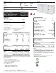
Product DataWIRING DIAGRAMSMulti V III Heat Recovery Outdoor Unit and PRVC1 Control KitFigure 14: Multi V III Heat Recovery Outdoor Unit and PRVC1 Control Kit Wiring Diagram. .Outdoor Unit Main BoardTransformerPRVC1Control Kit PCBPRVC1 Control KitDue to our policy of continuous product innovation, some specifications may change without notification.<strong>LG</strong> Electronics U.S.A., Inc., Englewood Cliffs, NJ. All rights reserved. “<strong>LG</strong> Life’s Good” is a registered trademark of <strong>LG</strong> Corp.17
PRODUCT INSTALLATIONAttaching the Low Ambient Cooling Kit Top Discharge ElbowStep 1.Turn OFF the power to the outdoor unit.Figure 15: Top of Outdoor Unit with Fan GuardRemoved.Step 2.Loosen the four screws that secure the fan guard to the top of the outdoor unit, andthen remove the fan guard.MULTI V Low Ambient Cooling Kit <strong>Installation</strong> <strong>Manual</strong>Step 3.Attach the top discharge elbow to the top of the outdoor unit with screws (included).Attaching the Top Discharge Elbow on Eight (8) to Twelve (12) Ton Capacity Outdoor Units.The top discharge elbow for ZLABKA02A Low Ambient Cooling Kit has two pieces - a left component and a right component. These must beconnected together before installation.Step 1.On the right top discharge elbow, crank the damper actuator to the closed position.Figure 16: Installed Top Discharge Elbow.Figure 17: Dampers in Closed Position.Step 2.Align the damper rod on the left top discharge elbow tothe hole on the side of the right top discharge elbow,insert, and push components together. Install on theoutdoor unit as described above.Figure 18: Damper Rod.Figure 19: Left and right top dischargeelbows connected.18Due to our policy of continuous product innovation, some specifications may change without notification.<strong>LG</strong> Electronics U.S.A., Inc., Englewood Cliffs, NJ. All rights reserved. “<strong>LG</strong> Life’s Good” is a registered trademark of <strong>LG</strong> Corp.
PRODUCT INSTALLATIONAttaching the Low Ambient Cooling Kit Side Wind BafflesNote:The right wind baffle is widerthan the left wind baffle. Makesure to attach the correct windbaffle to the correct side panel.Figure 20: Low Ambient CoolingKit Installed.Step 1.Remove the three (3) screws onthe outdoor unit side panel.Figure 21: Location of Screw Holes.Left SideRight SideScrewsFrontStep 2.Use the four (4) sheet-metal hangers to position the side wind baffle on the coil guard’s top and bottom crossbars. Line up the predrilledholes of the wind baffle to the side panel holes.Figure 22: Location of Hangers.Figure 23: Positioning the SideFigure 24: Close up of Wind BaffleWind Baffle.Hangers.<strong>Installation</strong>HangersStep 3.Using the side wind baffle as the template, markthe locations on the outdoor unit where additionalscrews (included) must be added. Remove the sidewind baffle, and predrill the holes using a drill bit.Step 4.Reposition the side wind baffle on the coil guard’s top and bottom crossbars. Securewith three (3) screws on each side. Repeat steps for the other side wind baffle.Figure 25: Attaching the Side Wind Baffle.Figure 26: Side Wind Baffle Installed.Note:Do not puncture the outdoor unit coil or otherinterior components when predrilling holes for thewind baffle screws. Maximum depth = Two (2)inches.Due to our policy of continuous product innovation, some specifications may change without notification.<strong>LG</strong> Electronics U.S.A., Inc., Englewood Cliffs, NJ. All rights reserved. “<strong>LG</strong> Life’s Good” is a registered trademark of <strong>LG</strong> Corp.19
PRODUCT INSTALLATIONAttaching the Low Ambient Cooling Kit Rear Wind BaffleStep 1.Insert the top edge of the rear wind baffle into the slot on the back of the outdoor unit.Figure 27: Top Edge of the Rear Wind Baffle.Figure 28: Top Edge of the Rear Wind Baffle Inserted.MULTI V Low Ambient Cooling Kit <strong>Installation</strong> <strong>Manual</strong>Step 2.Using the rear wind waffle as the template, mark the locations on the outdoor unit where holes need tobe predrilled for the screws — three (3) on each side, six (6) total. Remove the side wind baffle, andpredrill the holes using a drill bit.Note:Do not puncture the outdoor unit interior components when predrilling holes for the rear wind baffle screws.Maximum depth = Two (2) inches.Figure 29: Example of a RearWind Baffle Predrilled Hole.Step 3.Reposition the rear wind baffle into the slot on the back of the outdoor unit. Secure with three (3) screws on each side.20Due to our policy of continuous product innovation, some specifications may change without notification.<strong>LG</strong> Electronics U.S.A., Inc., Englewood Cliffs, NJ. All rights reserved. “<strong>LG</strong> Life’s Good” is a registered trademark of <strong>LG</strong> Corp.
PRODUCT INSTALLATIONInstalling the PRVC1 Control Kit in the Outdoor Unit FramesStep 1.Turn OFF power to outdoor unit, and remove the service panel and electric box panel.Note:• Install the PRVC1 Control Kit components on a flat surface in the outdoor unit frame with the included screws, otherwise, theproduct may not be anchored properly.• Do not damage the PRVC1 PCB as it may cause it to malfunction.Step 2A (For Heat Pump Outdoor Units).Attach the PRVC1 Control Kit transformer, terminal block, and PCB to the outdoor unit frame (as shown below) with screws (included). HeatPump outdoor unit frames include predrilled holes for the transformer and terminal block; holes must be predrilled on site for attaching the PCB.Figure 30: Location of PRVC1 Control Kit Components in Multi V III Heat Pump Outdoor Unit Frames.PRVC1 ControlKit Transformer(frame includespredrilled holes)PRVC1 ControlKit Terminal Block(frame includespredrilled holes)Electrical Wiring <strong>Installation</strong>Note:All field-supplied wiring(to connect the PRVC1Control Kit PCB to theOutdoor Unit PCB)should be a minimum ofAWG 22.PRVC1 ControlKit PCB (holesmust be predrilledon site)Due to our policy of continuous product innovation, some specifications may change without notification.<strong>LG</strong> Electronics U.S.A., Inc., Englewood Cliffs, NJ. All rights reserved. “<strong>LG</strong> Life’s Good” is a registered trademark of <strong>LG</strong> Corp.21
PRODUCT INSTALLATIONInstalling the PRVC1 Control Kit in the Outdoor Unit FramesMULTI V Low Ambient Cooling Kit <strong>Installation</strong> <strong>Manual</strong>Step 2B (For Heat Recovery Outdoor Units).Note:To allow for PRVC1 Control Kit installation, the heat recovery outdoor unit’s sub terminal blockmust be removed.1. Disconnect and discard the wires that connect the sub terminalblock to the main PCB terminal block.2. Disconnect the communication wires from the heat recovery unit/ indoor units (the bottom connections) on the sub terminal block.(Existing systems will have these wires already installed; newinstallations may not have these connections present.) Discardthe sub terminal block.Main PCB TerminalBlockSub Terminal BlockFigure 31: Location of the HeatRecovery Outdoor Unit Sub TerminalBlock.3. Connect these communication wires from the heat recovery unit / indoor units to the main PCB terminal block.4. To prevent communication errors, clamp these communication wires to the side of the electrical box.5. Install the PRVC1 Control Kit terminal block and transformer components in the area where the sub terminal block was located.Figure 32: Heat Recovery Unit Wiring Path without PRVC1Control Kit Components Installed.Sub TerminalBlockCommunicationWire PathFigure 33: Heat Recovery Unit Wiring Path with PRVC1 Control KitComponents Installed.Main PCBTerminal BlockPRVC1 Control KitTerminal Block andTransformerCommunicationWire PathNote:All field-supplied wiring (to connect the PRVC1 Control Kit PCB to theOutdoor Unit PCB) should be a minimum of AWG 22.Note:Clamp the Wires.It is imperative that the communication wiresare clamped to the side of the electrical box. Ifthe wires overlap, communication and operationerrors will occur.22Due to our policy of continuous product innovation, some specifications may change without notification.<strong>LG</strong> Electronics U.S.A., Inc., Englewood Cliffs, NJ. All rights reserved. “<strong>LG</strong> Life’s Good” is a registered trademark of <strong>LG</strong> Corp.
PRODUCT INSTALLATIONInstalling the PRVC1 Control Kit in the Outdoor Unit FramesStep 2B (For Heat Recovery Outdoor Units, continued).Attach the PRVC1 Control Kit transformer, the terminal block, and the PCB to the outdoor unit frame (as shown below) with screws(included). Holes must be predrilled on site for attaching the transformer, the terminal block, and the PCB to the Heat Recoveryoutdoor unit frames.Figure 34: Location of PRVC1 Control Kit components in Multi V III Heat Recovery Outdoor Unit Frames.PRVC1 Control Kit Terminal Block(holes must be predrilled onsite)PRVC1 Control Kit Transformer(holes must be predrilled onsite)Electrical Wiring <strong>Installation</strong>PRVC1 Control Kit PCB (holes must bepredrilled onsite)Note:All field-supplied wiring (to connect the PRVC1 Control Kit PCB to the Outdoor Unit PCB) should be a minimum of AWG 22.Due to our policy of continuous product innovation, some specifications may change without notification.<strong>LG</strong> Electronics U.S.A., Inc., Englewood Cliffs, NJ. All rights reserved. “<strong>LG</strong> Life’s Good” is a registered trademark of <strong>LG</strong> Corp.23
ELECTRICAL WIRING INSTALLATIONInstalling the PRVC1 Control Kit in the Outdoor Unit FramesOverview of Steps 3 to 10.Figure 35: Wiring Connections between the Main PCB of the Multi V III Heat Pump Outdoor Unit and the PRVC1 Control Kit.CN41MULTI V Low Ambient Cooling Kit <strong>Installation</strong> <strong>Manual</strong>JIG1 and JIG2220VPRVC1Control KitTransformer12V and GND (CN_PWR)PRVC1 ControlKit PCBGRD and 12VCN_OUTWire HarnessDamper Actuator24VPRVC1Control KitTerminalBlockControl Signal Wire0-10V Control Signal to Damper Actuator24V Power to Damper ActuatorNote:All field-supplied wiring (to connect the PRVC1 Control Kit PCB to the Outdoor Unit PCB) should be a minimum of AWG 22.24Due to our policy of continuous product innovation, some specifications may change without notification.<strong>LG</strong> Electronics U.S.A., Inc., Englewood Cliffs, NJ. All rights reserved. “<strong>LG</strong> Life’s Good” is a registered trademark of <strong>LG</strong> Corp.
ELECTRICAL WIRING INSTALLATIONInstalling the PRVC1 Control Kit in the Outdoor Unit FramesOverview of Steps 3 to 10, continued.Figure 36: Wiring Connections between the Main PCB of the Multi V III Heat Recovery Outdoor Unit and the PRVC1 Control Kit.CN45JIG1 and JIG2220VPRVC1Control KitTransformer12V and GND (CN_PWR)PRVC1 ControlKit PCBGND and 12VWire HarnessDamper ActuatorElectrical Wiring <strong>Installation</strong>CN_OUT24VPRVC1Control KitTerminalBlockControl Signal Wire0-10V Control Signal to Damper Actuator24V Power to Damper ActuatorNote:All field-supplied wiring (to connect the PRVC1 Control Kit PCB to the Outdoor Unit PCB) should be a minimum of AWG 22.Due to our policy of continuous product innovation, some specifications may change without notification.<strong>LG</strong> Electronics U.S.A., Inc., Englewood Cliffs, NJ. All rights reserved. “<strong>LG</strong> Life’s Good” is a registered trademark of <strong>LG</strong> Corp.25
PRODUCT INSTALLATIONInstalling the PRVC1 Control Kit in the Outdoor Unit FramesOverview of Steps 3 to 10, continued.Dual-frame systems with Master and Slave Outdoor Units will require an additional Low Ambient Control Kit terminal block and transformer(another Low Ambient Control kit must be purchased). Control signal is daisy-chained from the Low Ambient Control Kit PCB to the MasterOutdoor Unit. Only Master Outdoor Unit requires software onboarding.Figure 37: Low Ambient Control Kit Wiring Connections in Dual-Frame Heat Pump <strong>Systems</strong>.MULTI V Low Ambient Cooling Kit <strong>Installation</strong> <strong>Manual</strong>24VJIG1 and JIG2220VPRVC1 ControlKit TransformerPRVC1 ControlKit TerminalBlockMaster Outdoor Unit PCB12V and GND (CN_PWR)PRVC1 Control Kit PCBControl Signal WiresCN41GRD and 12VWire HarnessCN_OUTDamper Actuatorfor MasterOutdoor UnitMaster Unit 0-10VControl Signal toDamper ActuatorSlave Outdoor Unit PCBJIG1 and JIG2Damper Actuatorfor SlaveOutdoor Unit220VPRVC1 ControlKit TransformerPRVC1 ControlKit TerminalBlockSlave Unit 0-10VControl Signal toDamper Actuator24V Power to Damper Actuator24V Power to Damper ActuatorNote:• The Master Unit (damper actuator) 0-10V control signal wire connects to the PRVC1 Control Kit PCB A+ terminal.• The Slave Unit (damper actuator) 0-10V control signal wire connects to the PRVC1 Control Kit PCB B+ terminal in the master unit.• Control signal wires then connect from the PRVC1 Control Kit PCB A- and B- terminals to the PRVC1 Terminal Block (in the masterunit), bottom right.24VNote:• The Low Ambient Control Kit cannot be used with triple-frame systems.• All field-supplied wiring (to connect the PRVC1 Control Kit PCB to the Outdoor Unit PCB) should be a minimum of AWG 22.• Wires between the Master and Slave Outdoor Units cannot be longer than ten (10) feet.26Due to our policy of continuous product innovation, some specifications may change without notification.<strong>LG</strong> Electronics U.S.A., Inc., Englewood Cliffs, NJ. All rights reserved. “<strong>LG</strong> Life’s Good” is a registered trademark of <strong>LG</strong> Corp.
PRODUCT INSTALLATIONInstalling the PRVC1 Control Kit in the Outdoor Unit FramesOverview of Steps 3 to 10, continued.Dual-frame systems with Master and Slave Outdoor Units will require an additional Low Ambient Control Kit terminal block and transformer(another Low Ambient Control kit must be purchased). Control signal is daisy-chained from the Low Ambient Control Kit PCB to the MasterOutdoor Unit. Only Master Outdoor Unit requires software onboarding.Figure 38: Low Ambient Control Kit Wiring Connections in Dual-Frame Heat Recovery <strong>Systems</strong>.CN45Slave Outdoor Unit PCB220VPRVC1 ControlKit TransformerMaster Outdoor Unit PCBJIG1 and JIG212V and GND (CN_PWR)PRVC1 Control Kit PCBGRD and 12VWire HarnessCN_OUTDamper Actuatorfor MasterOutdoor UnitJIG1 and JIG2Damper Actuatorfor SlaveOutdoor Unit220VPRVC1 ControlKit TransformerElectrical Wiring <strong>Installation</strong>24VPRVC1 ControlKit TerminalBlockMaster Unit 0-10VControl Signal toDamper ActuatorSlave Unit 0-10VControl Signal toDamper ActuatorPRVC1 ControlKit TerminalBlockControl Signal Wires24V Power to Damper Actuator24V Power to Damper ActuatorNote:• The Master Unit (damper actuator) 0-10V control signal wire connects to the PRVC1 Control Kit PCB A+ terminal.• The Slave Unit (damper actuator) 0-10V control signal wire connects to the PRVC1 Control Kit PCB B+ terminal in the master unit.• Control signal wires then connect from the PRVC1 Control Kit PCB A- and B- terminals to the PRVC1 Terminal Block (in the masterunit), bottom right.Note:• The Low Ambient Control Kit cannot be used with triple-frame systems.• All field-supplied wiring (to connect the PRVC1 Control Kit PCB to the Outdoor Unit PCB) should be a minimum of AWG 22.• Wires between the Master and Slave Outdoor Units cannot be longer than ten (10) feet.24VDue to our policy of continuous product innovation, some specifications may change without notification.<strong>LG</strong> Electronics U.S.A., Inc., Englewood Cliffs, NJ. All rights reserved. “<strong>LG</strong> Life’s Good” is a registered trademark of <strong>LG</strong> Corp.27
PRODUCT INSTALLATIONInstalling the PRVC1 Control Kit in the Outdoor Unit FramesStep 3.Connect the blue 220V wires from the transformer to the JIG1 and JIG2 terminals on the main outdoor unit PCB. There is no polarity, so eachblue wire can be plugged in either terminal.Figure 39: Transformer to JIG1 / JIG2 Connection in Heat Pump Units.Figure 40: Transformer to JIG1 / JIG2 Connection in Heat RecoveryUnits.MULTI V Low Ambient Cooling Kit <strong>Installation</strong> <strong>Manual</strong>Step 4.Connect the red 24V wires from the transformer to the terminal block. There is polarity, so the 24V red wire must be connected to the top leftterminal, and the 0V red wire must be connected to the top right terminal.Figure 41: Transformer to Terminal Block in Heat Pump Units.Figure 42: Transformer to Terminal Block in Heat Recovery Units.Note:• PCB can accept only DC 12V power input. Do not use AC power input as it will cause serious damage to the unit.• All field-supplied wiring (to connect the PRVC1 Control Kit PCB to the Outdoor Unit PCB) should be a minimum of AWG 22.28Due to our policy of continuous product innovation, some specifications may change without notification.<strong>LG</strong> Electronics U.S.A., Inc., Englewood Cliffs, NJ. All rights reserved. “<strong>LG</strong> Life’s Good” is a registered trademark of <strong>LG</strong> Corp.
PRODUCT INSTALLATIONInstalling the PRVC1 Control Kit in the Outdoor Unit FramesStep 5.Connect the red and black actuator wires from the damper actuatorto the terminal block. There is polarity, so the red wire should beconnected to the bottom left terminal and the black wire should beconnected to the bottom right terminal.Figure 43: Black, Red, and Orange Wire Connections to Terminal Block.Step 6.Connect the orange control signal wire (field supplied) to the bottomright terminal of the terminal block and the A-terminal on the PRVC1Control PCB.Figure 44: Orange Control Signal Wire and White 0-10V Control SignalWire Connections to PRVC1 Control PCB A- and A+ Terminals.Electrical Wiring <strong>Installation</strong>Step 7.Connect the white 0-10V control signal wire from the damperactuator to the A+ terminal on the PRVC1 Control PCB.Note:All field-supplied wiring (to connect the PRVC1 Control Kit PCB to the Outdoor Unit PCB) should be a minimum of AWG 22.Due to our policy of continuous product innovation, some specifications may change without notification.<strong>LG</strong> Electronics U.S.A., Inc., Englewood Cliffs, NJ. All rights reserved. “<strong>LG</strong> Life’s Good” is a registered trademark of <strong>LG</strong> Corp.29
PRODUCT INSTALLATIONInstalling the PRVC1 Control Kit in the Outdoor Unit FramesStep 8.Connect the 12V wire (field supplied) from the PRVC1 Control PCB12V terminal (CN-PWR) to the 12V terminal on the Outdoor UnitMain PCB (on lower right-hand corner).Figure 47: 12V and GND Wire Connections on the PRVC1 Control PCB.Step 9.Connect the GND wire (field supplied) from the G terminal(CN-PWR) on the PRVC1 Control PCB to the GND terminalon the Outdoor Unit Main PCB.Figure 48: 12V and GND Wire Connections on the Outdoor Unit MainPCB.MULTI V Low Ambient Cooling Kit <strong>Installation</strong> <strong>Manual</strong>Step 10.Connect the PRVC1 Control Kit wire harness from the PCB CN-OUT terminal to the CN-41 terminal on the Heat Pump Outdoor Unit MainPCB, or to the CN-45 terminal on the Heat Recovery Outdoor Unit Main PCB.Figure 45: Wire Harness Terminal on PRVC1 Control PCB.Figure 46: Wire Harness Terminal on Outdoor Unit Main PCB.Note:All field-supplied wiring (to connect the PRVC1 Control Kit PCB to the Outdoor Unit PCB) should be a minimum of AWG 22.30Due to our policy of continuous product innovation, some specifications may change without notification.<strong>LG</strong> Electronics U.S.A., Inc., Englewood Cliffs, NJ. All rights reserved. “<strong>LG</strong> Life’s Good” is a registered trademark of <strong>LG</strong> Corp.
PRECOMMISSIONINGDip Switch SettingsDip Switch Settings on the PRVC1 Control Kit PCBLow Ambient Control Kit PCB includes an RS-485 communication module. To prevent erroneous communication between the Low AmbientControl Kit RS-485 module, and the outdoor unit RS-485 module, the Low Ambient Control Kit RS-485 module must be disabled using thesettings below.To disable:• Dip Switches 1, 2, and 3: ON• Dip Switch 4: OFFFigure 49: PRVC1 Control PCB Dip Switches.ONOFF1 2 3 4Reset ButtonNote:• After the dip switch setting is changed, the reset button must be pressed to reflect the setting.• Before operating the outdoor unit, check the PCB voltage signal.PrecommissioningDue to our policy of continuous product innovation, some specifications may change without notification.<strong>LG</strong> Electronics U.S.A., Inc., Englewood Cliffs, NJ. All rights reserved. “<strong>LG</strong> Life’s Good” is a registered trademark of <strong>LG</strong> Corp.31
PRECOMMISSIONINGDip Switch SettingsDip Switch Settings on the Heat Pump Outdoor Unit Main PCBDip Switches 11, 12, and 13: ON.Figure 50: Heat Pump Outdoor Unit Main PCB Dip Switches.ONONOFF1 2 3 4 5 6 7OFF1 2 3 4 5 6 71 2 3 4 5 6 7 8 9 10 11 12 13 14MULTI V Low Ambient Cooling Kit <strong>Installation</strong> <strong>Manual</strong>Note:Push the reset button after setting the dip switches.Dip Switch Settings on Heat Recovery Outdoor Unit SUB PCBDip Switches 11, 12, and 13: ON.ONOFFOFF1 2 3 4 5 6 7 8 9 10 1 2 3 4 5 6 7 8 9 101 2 3 4 5 6 7 8 9 10 11 12 13 14 15 16 17 18 19 20Note:Push the reset button after setting the dip switches.ONFigure 51: Heat Recovery Outdoor Unit SUB PCB Dip Switches.32Due to our policy of continuous product innovation, some specifications may change without notification.<strong>LG</strong> Electronics U.S.A., Inc., Englewood Cliffs, NJ. All rights reserved. “<strong>LG</strong> Life’s Good” is a registered trademark of <strong>LG</strong> Corp.
SEQUENCE OF LED / OPERATIONSSequence of LEDsThe LEDs on the PRVC1 PCB indicate when communication exists between the Outdoor Unit and the Control Kit.Figure 52: PRVC1 PCB LEDs.LED01LED01GLED02GLED03G• LED01: Blinks when the PRVC1 PCB sends an RS-485 signal to the Outdoor Unit.• LED01G: Not used.• LED02G: Blinks when the Outdoor Unit receives a TTL signal from the PRVC1 PCB.• LED03G: Blinks when the PRVC1 PCB sends a TTL signal to the Outdoor Unit.Sequence of Operations• Low Ambient Control Kit initiates when the ambient temperature drops below 32°F, and all indoor units are in cooling mode• When heat recovery systems are in synchronous operation (heating and cooling), louvers will be fully opened and the Low Ambient CoolingKit will be disabled.• Louvers will be closed when the system is OFF.Sequence of OperationsTable 1: Louver Openings per High Pressure Reading.High Pressure (psi) DC Output Discharge Damper Angle1 392 < HP 2V 0 (Closed)2 377 < HP < 392 4V 303 363 < HP < 377 7V 604 334 < HP < 363 8V 705 305 < HP ≤ 334 9V 806 HP < 305 10V 90 (Opened)Due to our policy of continuous product innovation, some specifications may change without notification.<strong>LG</strong> Electronics U.S.A., Inc., Englewood Cliffs, NJ. All rights reserved. “<strong>LG</strong> Life’s Good” is a registered trademark of <strong>LG</strong> Corp.33
MULTI V Low Ambient Cooling Kit <strong>Installation</strong> <strong>Manual</strong>34Due to our policy of continuous product innovation, some specifications may change without notification.<strong>LG</strong> Electronics U.S.A., Inc., Englewood Cliffs, NJ. All rights reserved. “<strong>LG</strong> Life’s Good” is a registered trademark of <strong>LG</strong> Corp.