eQUEST Building Energy Modeling Guide for LG ... - LG-VRF.com
eQUEST Building Energy Modeling Guide for LG ... - LG-VRF.com
eQUEST Building Energy Modeling Guide for LG ... - LG-VRF.com

You also want an ePaper? Increase the reach of your titles
YUMPU automatically turns print PDFs into web optimized ePapers that Google loves.
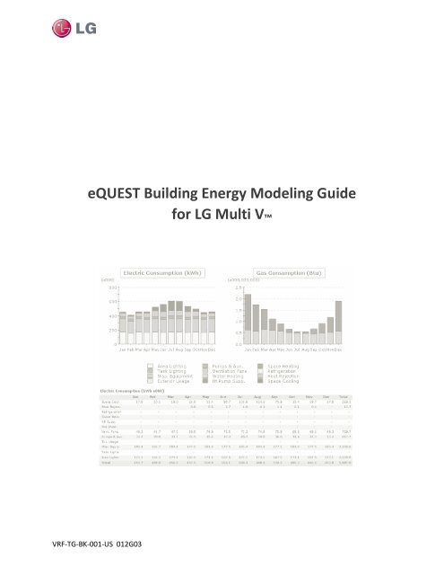
<strong>eQUEST</strong> <strong>Building</strong> <strong>Energy</strong> <strong>Modeling</strong> <strong>Guide</strong><strong>for</strong> <strong>LG</strong> Multi V <strong>VRF</strong>-TG-BK-001-US 012G03
IntroductionOverviewIntroductionThe <strong>eQUEST</strong> <strong>Building</strong> <strong>Energy</strong> <strong>Modeling</strong> <strong>Guide</strong> <strong>for</strong> <strong>LG</strong> Multi V contains stepby-stepinstructions <strong>for</strong> modeling <strong>LG</strong> Multi V system options. This documentprimarily draws from the DOE-2.2 <strong>Building</strong> <strong>Energy</strong> Use and Cost AnalysisProgram, Volume 1 and Volume 2. To download or learn more about <strong>eQUEST</strong>,please visit http://www.doe2.<strong>com</strong>/equest/.DisclaimerThis <strong>Building</strong> <strong>Energy</strong> <strong>Modeling</strong> <strong>Guide</strong> should be used as a guideline only.<strong>Building</strong> load and energy have been approximated <strong>for</strong> modeling purposesand vary with the input value of equipment (capacity, power input, etc.), andactual results will vary accordingly. The conclusions of this <strong>Modeling</strong> <strong>Guide</strong>do not guarantee actual energy costs or savings.This <strong>Modeling</strong> <strong>Guide</strong> and its associated <strong>eQUEST</strong> library file are intended asdesign and analysis guides to help designers optimize the design of <strong>LG</strong> MultiV <strong>VRF</strong> systems based on energy utilization. <strong>Modeling</strong> accuracy is highlydependent on user-supplied data. It is the user’s responsibility to understandhow the data entered affects program output and any predefined librariesare used only as guidelines <strong>for</strong> entering that data. The calculation results andreports shown in this guide and the <strong>eQUEST</strong> library file are meant to aid thesystem designer and are not a substitute <strong>for</strong> design services, judgment, orexperience.<strong>VRF</strong>-TG-BK-001-US 012G03 1
Importing Multi V Library FileImporting Multi V Library FileImporting the Library FileTo import the Multi V library file into <strong>eQUEST</strong>:1. Obtain the Multi V library file (Bdllib.dat) from your <strong>LG</strong> SalesRepresentative.2. Double click the <strong>eQUEST</strong> icon on your desktop to launch <strong>eQUEST</strong>. The<strong>eQUEST</strong> Startup Options dialog box appears:Figure 1: <strong>eQUEST</strong> startup options dialog box.Note:If this is not your first time opening <strong>eQUEST</strong>, open anexisting project instead.3. Click the OK button to create a new project. The Which Wizard dialogbox appears:<strong>VRF</strong>-TG-BK-001-US 012G03 3
Importing Multi V Library FileFigure 2: Which Wizard dialog box.4. Click the Schematic Design Wizard button.5. When the Wizard appears, click the Finish button. The Wizard closes.6. Click Tools > View File Locations > View <strong>eQUEST</strong> Data Directory.The <strong>eQUEST</strong> data directory appears in Windows Explorer (oftenC:\Documents and Settings\Administrator\My Documents\<strong>eQUEST</strong> 3-64 Data\DOE-2):Figure 3: Locating the library file.7. Double click the DOE-2 subdirectory. A list of files appears:<strong>VRF</strong>-TG-BK-001-US 012G03 4
Importing Multi V Library FileFigure 4: DOE-2 subdirectory.8. Rename the Bdllib.dat file to original_BDllib.dat. That way you canreturn to the default file if the need arises.9. Drag and drop the replacement Bdllib.dat file that you downloaderearlier into the Window Explorer dialog box. The file appears in thedialog box.10. Close the dialog box.11. In <strong>eQUEST</strong> click File > Exit to close the program.Testing the Library FileTo test the Multi V library file in <strong>eQUEST</strong>:1. On your desktop double click the <strong>eQUEST</strong> icon again. The programappears.2. Click Mode > Detailed Data Edit.3. Click the Air-Side HVAC button. The Air-Side HVAC pane appears.4. To the left of the pane, locate the Per<strong>for</strong>mance Curves folder in thetree.5. Right click the folder and select Create Curve Fit. The Create Curve Fitdialog box appears:<strong>VRF</strong>-TG-BK-001-US 012G03 5
Importing Multi V Library FileFigure 5: Create Curve Fit dialog box.6. Click the Load Component from Library button. The Curve FitLibrary Selection dialog box appears.Figure 6: Curve Fit Library Selection dialog box.7. Select MultiV 3 (HP) in the Category list. The Entry list populates withMulti V III outdoor units.8. Click the applicable outdoor unit in the Entry list.9. Click the OK button. The dialog box disappears, and the outdoor unitappears in the Curve Fit Name box on the Create Curve Fit dialog box.10. Click the OK button. The dialog box disappears, and the Per<strong>for</strong>manceCurve Properties dialog box appears:<strong>VRF</strong>-TG-BK-001-US 012G03 6
Importing Multi V Library FileFigure 7: Per<strong>for</strong>mance Curve Properties dialog box.11. Click the Done button. The outdoor unit now appears in thePer<strong>for</strong>mance Curves folder.<strong>VRF</strong>-TG-BK-001-US 012G03 7
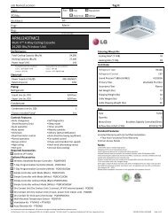
Case StudyCase StudyThis document uses multiple sources of in<strong>for</strong>mation to streamline the energymodeling process <strong>for</strong> variable refrigerant flow (<strong>VRF</strong>) systems. This casestudy features a building that is served by a <strong>VRF</strong> system. This studydemonstrates how to model the indoor units, piping, and outdoor units.Figure 8: <strong>eQUEST</strong> main window.To model the building’s energy use:1. We determine systems loads by space or zone, using the loadcalculation results from <strong>eQUEST</strong>. For example, if four arbitrary zonesare created, the peak loads of the might appear as follows:Zone 1 = 24,000 Btu/hrZone 2 = 24,000 Btu/hrZone 3 = 24,000 Btu/hrZone 4 = 24,000 Btu/hr2. Our building’s location is Atlanta, so the design temperature is 94°F.3. We select an indoor unit (IDU) <strong>for</strong> each zone or space using the <strong>LG</strong> MultiV III product line. We decide on four Four-Way Ceiling Cassettes.4. We inspect the indoor unit capacity tables <strong>for</strong> those units, consideringthe indoor and outdoor temperatures. Select units whose capacity is thenearest to or greater than the anticipated load. Are choices were asfollows:<strong>VRF</strong>-TG-BK-001-US 012G03 8
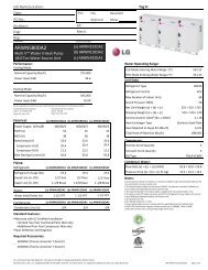
Case StudyNote:Individual indoor unit capacity is subject to changedepending on what outdoor units are used. Actual capacityhas to be calculated according to the <strong>com</strong>bination by usingthe outdoor unit capacity table.• Zone 1 = 24,000 Btu/hr: ARUN243TMC2. 24,000 Btu/hr load: one2.0 ton unit, 24,000 Btu/h. Capacity index (CI) = 24• Zone 2 = 24,000 Btu/hr: ARUN243TMC2. 24,000 Btu/hr load: one2.0 ton unit, 24,000 Btu/h. CI = 24• Zone 3 = 24,000 Btu/hr: ARUN243TMC2. 24,000 Btu/hr load: one2.0 ton unit, 24,000 Btu/h. CI = 24• Zone 4 = 24,000 Btu/hr: ARUN243TMC2. 24,000 Btu/hr load: one2.0 ton unit, 24,000 Btu/h. CI = 245. We select an outdoor unit <strong>for</strong> the loads from our <strong>LG</strong> Multi V III productline. We view allowable unit <strong>com</strong>binations in the Indoor UnitCombination Total Capacity Index Table in the appropriate <strong>LG</strong>Engineering Product Data Book (EPDB). In general, we choose outdoorunits based on the location of the unit, zoning, and purpose of therooms. The indoor and outdoor unit <strong>com</strong>bination is determined by their<strong>com</strong>bination ratios, which is the ratio of the indoor unit capacity to theoutdoor unit capacity, expressed as a percentage. Optimally we shoot<strong>for</strong> a 100% ratio or slightly under. Based on the following:Total Load = 8 tons = 96,000 Btu/h = 96, CI = 96IDU Capacity = 8 tons = 96,000 Btu/h, CI = 96We chose an <strong>LG</strong> Multi V III ARUN096DT3 (8 tons = 96,000 Btu/h, CI = 96).Figure 9 <strong>LG</strong> Multi V III ARUN096DT3<strong>VRF</strong>-TG-BK-001-US 012G03 9
Case Study6. We know the <strong>com</strong>bination ratio is good because 96/96 = 1 = 100%.7. Next, we modify the indoor unit capacity index based on an indoortemperature of 67°F WB, once again using the appropriate EPDB. Wearrive at the following results:• Zone 1: Initial CI = 24. Adjusted CI = 24.2 MBH (20.3 MBH sensible).• Zone 2: Initial CI = 24. Adjusted CI = 24.2 MBH (20.3 MBH sensible).• Zone 3: Initial CI = 24. Adjusted CI = 24.2 MBH (20.3 MBH sensible).• Zone 4: Initial CI = 24. Adjusted CI = 24.2 MBH (20.3 MBH sensible).For a sum of IDU outputs of 96.8 MBH.8. Next, we modify ODU capacity <strong>for</strong> any piping losses. For this calculationwe assume that we have 65 feet of pipe from the ODU to farthest IDU,where the main pipe is 30 feet long and there is 40 feet of branch pipe.Our farthest IDU is 9.8 feet below the ODU, which is placed on the roof.Our overall equivalent pipe length, L, is as follows:L = (Lmain × Cf) + LbranchL = 30 ft × 1.0 + 130 ft. = 160.0 ft.Cf represents the correction factor, which also <strong>com</strong>es <strong>for</strong> the EPDB. Wethen correct <strong>for</strong> the elevation change, Hp. Using Cf and Hp, wedetermine our overall capacity correction factor using the followingchart:Figure 10 Capacity Correction FactorThe result is a cooling capacity of α = 0.98 based on the overall equivalentpipe length, L, and the level difference, Hp.<strong>VRF</strong>-TG-BK-001-US 012G03 10
Case StudyNote:Note:If you are interested in learning more about piping lossesand Multi V III system design, download the EPDB from <strong>LG</strong>-<strong>VRF</strong>.<strong>com</strong>.The <strong>LG</strong> Air-Conditioner Technical Solution softwareautomates much of the piping loss calculation. You candownload it at <strong>LG</strong>-<strong>VRF</strong>.<strong>com</strong>.9. Next, we correct <strong>for</strong> temperature effects on outdoor unit capacity usingthe following input data:• CR = 100%• Tout_db = 94°F• Tin_wb = 67°FWe arrive at a new total cooling capacity of 95.79 MBH with anelectrical power input of 6.64 kW <strong>for</strong> the <strong>com</strong>pressors and the outdoorunit’s fan motor.10. Next, we correct with a safety factor. A 100% safety factor is assumed tobe sufficient with a 100% CR, so there is zero net change.95,790[Btu/hr] × 100% = 95,790Btu/hr11. We then ensure that the indoor unit capacity divided by the modifiedoutdoor unit capacity is greater than the peak cooling or heating load.Otherwise the indoor unit capacity must be increased.12. Next, we input the air-side HVAC system parameters in <strong>eQUEST</strong>:Figure 11: Unitary Power (Cooling) Tab.<strong>VRF</strong>-TG-BK-001-US 012G03 11
Case StudyCooling data:• COOLING-CAPACITY : 95,790• Cooling EIR = 0.2399• (Cooling Capacity: 96.0 Mbh, Power Input: 6.75kW, EER =14.2)• Compressor type: Variable Speed• Minimum Unload ratio: 0.15• Min hot gas bypass ratio: 0.15• Crankcase heat: 0.060kW• Crankcase Max Temperature: 40°F• Per<strong>for</strong>mance Curves:• COOL-EIR-FT : ARUN096DT3• COOL-EIR-FPLR : ARUN096DT3• COOL-EIR-LS-FT : RESVVT cool Lo speed EIR-FRPM• COOL-CAP-FT : ARUN096DT3• COOL-SH-FT : ARUN096DT3Figure 12: Capacity Curves (Cooling) Tab.<strong>VRF</strong>-TG-BK-001-US 012G03 12
Case StudyFigure 13: Unitary Power (Heating) Tab.Heating data:• HEAT-SOURCE : HEAT-PUMP• HEATING-CAPACITY : -101,370• HEATING EIR = 0.2167• (HEATING Capacity: 108.0 Mbh, Power Input: 6.86kW, COP =4.61)• MAX-SUPPLY-T : 105• Per<strong>for</strong>mance Curves:• HEAT-EIR-FT : ARUN096DT3• HEAT-EIR-FPLR: ARUN096DT3• HEAT-EIR-LS-FT : RESVVT heat Lo speed EIR-FRPM<strong>VRF</strong>-TG-BK-001-US 012G03 13
Case StudyFigure 14: Cap Curves/Waste Ht (Heating) Tab.Figure 15: Supp Heat/Defrost (Heating) Tab.• HP-SUPP-SOURCE: Not installed• DEFROST-TYPE : REVERSE-CYCLE• DEFROST-CTRL : ON-DEMAND• DEFROST-T : Set to 40°F.<strong>VRF</strong>-TG-BK-001-US 012G03 14
Case Study13. We then add fan parameters. We enter the total static pressure (TSP) orfan power (kW/cfm) of the system supply fan.Note:TSP includes also includes pressure drops across filters andother internal air handler <strong>com</strong>ponents.Depending on the system type, you can set fans to cycle at night. Select“no OA at night” if there is no economizer or “no OA at night +economizer” plus the economizer type if your system has aneconomizer.Note:You may need to remove the economizer low limit in detailmode.For our system, we have four 4-Way Ceiling cassettes (ARUN243TMC2),each with a 30W fan motor moving air at 600 cfm.Figure 16: Fan Power and Control (Fans) Tab.Refer to the EPDB <strong>for</strong> the indoor units you intend to model to find theTSP and other data. Pressure losses should include filters, coils, and thedistribution system. You should use the full-load power of the supplyfan per unit of supply air flow rate at sea level, using either SUPPLY-STATIC or SUPPLY-KW/FLOW. <strong>eQUEST</strong> calculates the part-load powerconsumption of the supply fan versus the part-load characteristics<strong>VRF</strong>-TG-BK-001-US 012G03 15
Case Studycorresponding to the control mode selected. You should choose thevariable speed option, specify the supply fan placement, and specify thedesign air flow capacity of the indoor units’ supply fans.Figure 17: Flow Parameters (Fan) Tab.Both the minimum and maximum air flow rates through a supply fanare expressed as a fraction of the design flow rate. We chose to set therate to INTERMITTENT where the indoor unit fan operates as with theCONTINIOUS setting but only <strong>for</strong> a fraction of an hour required <strong>for</strong>space heating or cooling.14. Next, we run the simulation.<strong>VRF</strong>-TG-BK-001-US 012G03 16
Case StudyFigure 18: Simulation calculation in progress.15. Finally, we inspect the results:Figure 19: Simulation results.<strong>VRF</strong>-TG-BK-001-US 012G03 17
Case StudyThe results consist of reports in three main categories:• Verification reports that summarize the model input, as well as designvalues calculated by the program.• Summary reports that present the results of the program simulation.• Hourly reports that tabulate the hourly values of a user-selected set ofsimulation variables.<strong>VRF</strong>-TG-BK-001-US 012G03 18
ReferencesReferences• DOE-2.2 <strong>Building</strong> <strong>Energy</strong> Use and Cost Analysis Program, Volume 1Basic, Lawrence Berkeley National Laboratory and James J. Hirsch &Associates (JJH).• DOE-2.2 <strong>Building</strong> <strong>Energy</strong> Use and Cost Analysis Program, Volume 2Dictionary, Lawrence Berkeley National Laboratory and James J. Hirsch& Associates (JJH).• ASHRAE/IESNA Standard 90.1-2007 : http://www.ashrae.org.<strong>VRF</strong>-TG-BK-001-US 012G03 19