Combined overcurrent & earth-fault relay type SPAJ - ABB Group
Combined overcurrent & earth-fault relay type SPAJ - ABB Group
Combined overcurrent & earth-fault relay type SPAJ - ABB Group

Create successful ePaper yourself
Turn your PDF publications into a flip-book with our unique Google optimized e-Paper software.
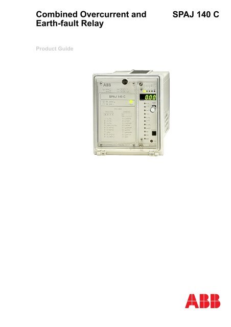
<strong>Combined</strong> Overcurrent andEarth-<strong>fault</strong> Relay<strong>SPAJ</strong> 140 CProduct Guide
<strong>Combined</strong> Overcurrent and Earth-<strong>fault</strong>Relay<strong>SPAJ</strong> 140 C1MRS750361-MBGIssued: April 1999Status: UpdatedVersion: C/18.04.2006Data subject to change without noticeFeatures • Three-phase, low-set phase <strong>overcurrent</strong>unit with definite time or inverse definiteminimum time (IDMT) characteristic• Three-phase, high-set phase <strong>overcurrent</strong>unit with instantaneous or definite timeoperation• Low-set <strong>earth</strong>-<strong>fault</strong> unit with definite time orinverse definite minimum time (IDMT) characteristic• High-set <strong>earth</strong>-<strong>fault</strong> unit with instantaneousor definite time operation• Built-in circuit-breaker failure protection• Two heavy-duty and four signal output<strong>relay</strong>s• Output <strong>relay</strong> matrix allowing start or trip signalsfrom the protection stages to be routedto the desired output <strong>relay</strong>• Local display of measured and set valuesand data recorded at the moment of a <strong>fault</strong>• Reading and writing of setting values eithervia local display and front panel push-buttonsor from higher-level systems over theserial interface and the fibre-optic bus• Self-supervision system continuously monitoringthe operation of the electronics andthe microprocessor• Powerful software support for parameterizationof the <strong>relay</strong>, for reading measuredand recorded values, events, etc., and forstoring readings• Member of the SPACOM product familyand <strong>ABB</strong>’s Distribution Automation system• CE marking according to the EC directivefor EMCApplicationThe combined <strong>overcurrent</strong> and <strong>earth</strong>-<strong>fault</strong><strong>relay</strong> <strong>SPAJ</strong> 140 C is intended to be used forthe selective short-circuit and <strong>earth</strong>-<strong>fault</strong> protectionof radial feeders in solidly <strong>earth</strong>ed,resistance <strong>earth</strong>ed or impedance <strong>earth</strong>edpower systems. The integrated protection<strong>relay</strong> includes an <strong>overcurrent</strong> unit and an<strong>earth</strong>-<strong>fault</strong> unit with flexible tripping and signallingfacilities. The <strong>overcurrent</strong> and <strong>earth</strong><strong>fault</strong><strong>relay</strong>s can also be used for other applicationsrequiring single-, two-, or three-phase<strong>overcurrent</strong> protection. The combined <strong>overcurrent</strong>and <strong>earth</strong>-<strong>fault</strong> <strong>relay</strong> includes a circuit-breakerfailure protection unit.The combined <strong>overcurrent</strong> and <strong>earth</strong>-<strong>fault</strong><strong>relay</strong> <strong>SPAJ</strong> 140 C is part of <strong>ABB</strong>’s DistributionAutomation concept, the complete <strong>ABB</strong>solution for the control and management ofelectric power systems.3
<strong>Combined</strong> Overcurrent and Earth-<strong>fault</strong>Relay<strong>SPAJ</strong> 140 C1MRS750361-MBGDesignThe combined <strong>overcurrent</strong> and <strong>earth</strong>-<strong>fault</strong><strong>relay</strong> is a secondary <strong>relay</strong> to be connected tothe current transformers of the object to beprotected. The three-phase <strong>overcurrent</strong> unitand the <strong>earth</strong>-<strong>fault</strong> unit continuously measurethe phase currents and the neutral current ofthe object. On detection of a <strong>fault</strong> the <strong>relay</strong>starts, trips the circuit breaker, provides analarm signal, records <strong>fault</strong> data, etc., in accordancewith the requirements of the applicationand the <strong>relay</strong> configuration.When the phase current exceeds the set startcurrent of the low-set stage I>, the <strong>overcurrent</strong>unit starts and, after a preset start time, itdelivers a start signal. When the set operatetime, at definite time operation, or the calculatedoperate time, at inverse time operation,elapses, the <strong>overcurrent</strong> unit operates. In thesame way, the high-set stage I>> of the <strong>overcurrent</strong>unit starts when the set start current isexceeded and delivers a start signal after thepreset (~40 ms) start time. When the set operatetime has elapsed, the <strong>overcurrent</strong> unitoperates.When the <strong>earth</strong>-<strong>fault</strong> current exceeds the setstart current of the low-set stage I 0 >, the<strong>earth</strong>-<strong>fault</strong> unit starts and, after a preset starttime, it delivers a start signal. When the setoperate time, at definite time operation, or thecalculated operate time, at inverse time operation,elapses, the <strong>earth</strong>-<strong>fault</strong> unit operates. Inthe same way, the high-set stage I 0 >> of the<strong>earth</strong>-<strong>fault</strong> unit starts, when the set start currentis exceeded, and delivers a start signalafter the preset (~50 ms) start time. Once theset operate time has elapsed, the <strong>earth</strong>-<strong>fault</strong>unit operates.The low-set stage of the <strong>overcurrent</strong> unit andthe low-set stage of the <strong>earth</strong>-<strong>fault</strong> unit maybe given definite time or inverse definite minimumtime (IDMT) characteristic. The IDMTcharacteristic includes six time/current curvesets. Four of the curve sets comply with theBS 142 and IEC 255 and are named “Normalinverse”, “Very inverse”, “Extremelyinverse” and “Long-time inverse”. The twoadditional inverse time curve sets complywith <strong>ABB</strong> standards and are called “RI” and“RXIDG”.By appropriate configuration of the output<strong>relay</strong> matrix, the start signals of the <strong>overcurrent</strong>and <strong>earth</strong>-<strong>fault</strong> units are obtained as contactfunctions. The start signals can be usedfor blocking co-operating protection <strong>relay</strong>s,and for signalling.The <strong>relay</strong> includes one external binary input,which is controlled by an external controlvoltage. The function of the control input isdetermined by a selector switch in the protection<strong>relay</strong> module. The control input can beused for blocking the operation of one ormore protection stages, for resetting a latchedoutput <strong>relay</strong> in the manual reset mode or forswitching between main and second settingbanks.Data communicationThe <strong>relay</strong> is provided with a serial interfaceon the rear panel. By means of a bus connectionmodule <strong>type</strong> SPA-ZC 17 or SPA-ZC 21the <strong>relay</strong> can be connected to the fibre-opticSPA bus. The bus connection module <strong>type</strong>SPA-ZC 21 is powered from the host <strong>relay</strong>,whereas the bus connection module SPA-ZC 17 is provided with a built-in power unit,which can be fed from an external securedpower source. The <strong>relay</strong> communicates withhigher-level data acquisition and control systemsover the SPA bus.Self-supervisionThe <strong>relay</strong> incorporates a sophisticated selfsupervisionsystem with auto-diagnosis,which increases the availability of the <strong>relay</strong>and the reliability of the system. The selfsupervisionsystem continuously monitors thehardware and the software of the <strong>relay</strong>. Thesystem also supervises the operation of theauxiliary supply module and the voltagesgenerated by the module.When a permanent internal <strong>relay</strong> <strong>fault</strong> isdetected, the IRF indicator on the <strong>relay</strong> frontpanel is lit. At the same time the output <strong>relay</strong>of the self-supervision system operates and a<strong>fault</strong> message is transmitted to the higherlevelsystem over the serial bus. Further, inmost <strong>fault</strong> situations, a <strong>fault</strong> code is shown inthe display of the protection <strong>relay</strong> module.The <strong>fault</strong> code indicates the <strong>type</strong> of the <strong>fault</strong>that has been detected.Auxiliary supply voltageThe auxiliary supply of the <strong>relay</strong> is obtainedfrom an internal plug-in <strong>type</strong> power supplymodule. Two auxiliary power module versionsare available: <strong>type</strong> SPTU 240R1 for thesupply voltage range 80…265 V ac/dc and<strong>type</strong> SPTU 48R1 for the supply voltage range18…80 V dc. The power supply moduleforms the internal voltages required by theprotection <strong>relay</strong> and the I/O module.4
<strong>Combined</strong> Overcurrent and Earth-<strong>fault</strong>Relay<strong>SPAJ</strong> 140 C1MRS750361-MBGTechnical dataTable 1: Energizing inputs, <strong>overcurrent</strong> unitTerminals 1-3, 4-6, 7-9 1-2, 4-5, 7-8Rated current I n 1 A 5 AThermal withstand continuously 4 A 20 Acapabilityfor 10 s 25 A 100 Afor 1 s 100 A 500 ADynamic current Half-wave value 250 A 1250 Awithstand capabilityInput impedance
<strong>Combined</strong> Overcurrent and Earth-<strong>fault</strong>Relay<strong>SPAJ</strong> 140 C1MRS750361-MBGTechnical data (cont´d)Table 4: Control input, communication and power supplyExternal control input Terminals 10-11Control voltage level18…265 V dc or80…265 V acCurrent drain at activated input2…20 mAData communication Transmission mode Fibre-optic serial busData codeASCIISelectable data transfer rates4800 or 9600 BdBus connection module, for plastic core cables SPA-ZC 21BBpowered from the host for glass fibre cables SPA-ZC 21MM<strong>relay</strong>Bus connection module, for plastic core cables SPA-ZC 17BBpowered from the host for glass fibre cables SPA-ZC 17MM<strong>relay</strong> or from an externalpower sourceAuxiliary supply modules Power supply and I/Omodules, rated voltagesand operative rangeSPTU 240R1110/120/230/240 V ac,110/125/220 V dc,80…265 V ac/dcSPTU 48R124/48/60 V dc,18…80 V dcPower consumption under quiescent ~4 Wconditionsunder operatingconditions~6 WTable 5: Relay module SPCJ 4D29, <strong>overcurrent</strong> unitFeatures Stage I> Stage I>>Start current at definite time 0.5…5.0 × I n 0.5…40.0 × I n and ∞at inverse time 0.5…2.5 × I n –Start time, typically 50 ms 40 msOperate time at definite time characteristic 0.05…300 s 0.04…300 sTime/current characteristic at inverse mode Extremely inverse –Very inverseNormal inverseLong-time inverseRI <strong>type</strong> inverseRXIDG <strong>type</strong> inverseTime multiplier k 0.05…1.0 –Reset time, typically 40 ms 40 msRetardation time
<strong>Combined</strong> Overcurrent and Earth-<strong>fault</strong>Relay<strong>SPAJ</strong> 140 C1MRS750361-MBGTechnical data (cont´d)Table 6: Relay module SPCJ 4D29, <strong>earth</strong>-<strong>fault</strong> unitFeatures Stage I 0 > Stage I 0 >>Start current 0.1…0.8 × I n 0.1…10.0 × I n and ∞Start time, typically 60 ms 40 msOperate time at definite time characteristic 0.05…300 s 0.05…300 sTime/current characteristic at inverse time modeExtremely inverseVery inverseNormal inverseLong-time inverseRI <strong>type</strong> inverseRXIDG <strong>type</strong> inverseTime multiplier k 0.05…1.0 –Reset time, typically 40 ms 40 msRetardation time 100 MΩ, 500 V dc2.5 kV1.0 kV4 kV, 5/50 ns2 kV, 5/50 ns8 kV6 kV10 V/m, f = 80…1000 MHz10 V, f = 150 kHz…80 MHz68…265 V0…200 ms0…30 ms0…160 ms7
<strong>Combined</strong> Overcurrent and Earth-<strong>fault</strong>Relay<strong>SPAJ</strong> 140 C1MRS750361-MBGTable 7: Tests and standardsMechanical testSeismic test(ANSI/IEEE C37.98-1987),operating basis <strong>earth</strong>-quake testSeismic test(ANSI/IEEE C37.98-1987), safeshut down <strong>earth</strong>-quake testVibration testShock/bump test(IEC 60255-21-2)Corrosion test0.5…5.25 g0.5…7.5 g2…13.2 Hz, ±1.0 mm13.2…100 Hz, ±0.7 g20 g, 1000 bumps/directionBattelle testEnvironmental conditions Service temperature range -10…+55°CTransport and storagetemperature range(IEC 60068-2-8)-40…+70°CDamp heat test(IEC 60068-2-3)Degree of protection by enclosurewhen panel mountedWeight
<strong>Combined</strong> Overcurrent and Earth-<strong>fault</strong>Relay<strong>SPAJ</strong> 140 C1MRS750361-MBGBlock diagram63 1 23 4 5 6 7 89 25 26 27<strong>SPAJ</strong> 140 CL1L2L30I 0+++ (~)- (~)U aux+IRF START 1 START 2 SIGNAL 1 SIGNAL 2TRIP11 10 62 61 70 71 7274 7577 7880 8168 6965 66++++++FEDCBAU2+ -TS1SS1SS2SS3TS21111 LATCHING 1SGB/6SGB/7SGB/1U13I>IRFT1SGB/23I>>T3SGB/3Io>T5SGB/4Io>>T7SGB/5RC SETTINGS I/OSGB/8 SGF/4RESETT90.1...1sT2T4T6T8-I-1 A5 ASGR1/2SGR1/4SGR1/6SGR1/8SGR2/8U3RRx TxSERIALPORTTRIPU11 A5 A1 A5 A1 A5 ASGR3/1SGR3/2SGR3/3SGR3/4SGR3/5SGR3/6SGR3/7SGR3/8SGR1/1SGR1/3SGR1/5SGR1/7SGR2/1SGR2/3SGR2/5SGR2/7SGR2/2SGR2/4SGR2/6SPA-ZC_EXTERNALCONTROL~Fig. 8Block diagram and sample connection diagramB<strong>SPAJ</strong>1409
<strong>Combined</strong> Overcurrent and Earth-<strong>fault</strong>Relay<strong>SPAJ</strong> 140 C1MRS750361-MBGMounting anddimensionsFlush mounting1423025021618634129 ±1162136139 ±1Panel cutoutdim100Fig. 1Flush-mounting <strong>relay</strong> case (dimensions in mm)Semi-flush mountingabRaising frameSPA-ZX 111SPA-ZX 112SPA-ZX 113a17613696b74114154SFM100_1Fig. 2Semi-flush mounting <strong>relay</strong> case (dimensions in mm)Mounting in 19 inch cabinetsand framesAn ancillary mounting plate, height 4U(~177 mm), is recommended to be used whenthe protection <strong>relay</strong>s are to be mounted in 19inch frames or cabinets. The ancillary mountingplate <strong>type</strong> SPA-ZX 104 accommodatesthree <strong>relay</strong>s, <strong>type</strong> SPA-ZX 105 two <strong>relay</strong>s and<strong>type</strong> SPA-ZX 106 one <strong>relay</strong>.Projecting mountingWhen projecting mounting is preferred, a<strong>relay</strong> case <strong>type</strong> SPA-ZX 110 is used. The<strong>relay</strong> case for projecting mounting is providedwith front connectors.SPA-ZX104SPA-ZX105SPA-ZX106+0,4482,6 –0 (19")SPA-ZX110SPA-ZX11510158115ø6263312292101,621,57+0,4177 –0 (4U)115698104_6_10Fig. 3Mounting cabinets and frames as well as projecting mounting (dimensions in mm)10
<strong>Combined</strong> Overcurrent and Earth-<strong>fault</strong>Relay<strong>SPAJ</strong> 140 C1MRS750361-MBGOrderingWhen ordering, please specify:Ordering informationOrdering example1. Type designation and quantity <strong>SPAJ</strong> 140 C, 5 pieces2. Order number RS 611 006-AA3. Rated values I n =5 A, f n =50 Hz4. Auxiliary voltage U aux =110 V dc5. Accessories -6. Special requirements -Order numbers<strong>Combined</strong> <strong>overcurrent</strong> and <strong>earth</strong>-<strong>fault</strong> <strong>relay</strong><strong>SPAJ</strong> 140 C without test adapter<strong>Combined</strong> <strong>overcurrent</strong> and <strong>earth</strong>-<strong>fault</strong> <strong>relay</strong><strong>SPAJ</strong> 140 C including test adapter RTXP 18The last two letters of the order number indicate therated frequency f n and the auxiliary voltage U aux ofthe <strong>relay</strong> as follows:RS 611 006-AA, CA, DA, FARS 611 206-AA, CA, DA, FAAA equals f n = 50 Hz and U aux = 80…265 V ac/dcCA equals f n = 50 Hz and U aux = 18…80 V dcDA equals f n = 60 Hz and U aux = 80…265 V ac/dcFA equals f n = 60 Hz and U aux = 18…80 V dcReferencesAdditional informationUser’s manual and technical description “<strong>Combined</strong><strong>overcurrent</strong> and <strong>earth</strong>-<strong>fault</strong> <strong>relay</strong> <strong>SPAJ</strong> 140 C”1MRS 750629-MUM EN11
<strong>ABB</strong> OyDistribution AutomationP.O. Box 699FI-65101 Vaasa, FINLANDTel +358 10 22 11Fax +358 10 224 1094www.abb.com/substationautomation