Emax Low voltage air circuit-breakers - ABB Download Center
Emax Low voltage air circuit-breakers - ABB Download Center
Emax Low voltage air circuit-breakers - ABB Download Center

Create successful ePaper yourself
Turn your PDF publications into a flip-book with our unique Google optimized e-Paper software.
Main characteristicsRangesInstallationsOvercurrent releasesand relative accessoriesAccessoriesCircuit-<strong>breakers</strong> applicationsOverall dimensionsElectrical <strong>circuit</strong> diagramsOrdering codes
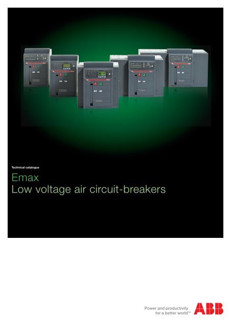
Continuing the tradition of <strong>ABB</strong> SACE, the new <strong>Emax</strong> range offers performancesat the top of its category. The <strong>Emax</strong> range offers you a great advantage:with the increased performances, you can use the smaller <strong>circuit</strong>-breakerframes, obtaining considerable savings both in economic terms and inphysical space within the switchgear. <strong>Emax</strong> E1 now offers current ratingsup to 1600A, whilst <strong>Emax</strong> E3 is enhanced by version V with top of therange performances. Always aware of the rapid changes in the market,<strong>ABB</strong> SACE has made some specific versions to cover new applicationsand simplify retrofitting operations.
The new <strong>Emax</strong> range shines like a light from within: the new generation of protection trip units is fittedwith the latest advances in electronics, offering individual bespoke solutions for control and protection.The new trip units, which are amazingly versatile and simple to use, offerimportant innovations, such as the brand-new intuitive operator interfaceallowing complete control of the system with just a few simple keystrokes.Furthermore, there are new protections, new alarms andconnection to handheld and laptop PCs using Bluetooth technology.The re-engineered hardware architecture allows flexible andprecise configuration. With the new <strong>Emax</strong> it is no longernecessary to completely replace the trip unit - simply add themodule which satisfies your requirements: a great advantage,both in terms of flexibility and customisation.
The new <strong>Emax</strong> have received innumerableinternational certifications and approval bythe major shipping registers.
Careful selection of materials, meticulous assembly and a rigorous testing stage make the new <strong>Emax</strong>an extremely reliable and sturdy product, able to withstandhigh dynamic and thermal stresses for longerthan any other <strong>circuit</strong>-breaker in its category.With the new standardised system of accessoriesstudied and made for the new <strong>Emax</strong>, workbecomes easier, convenient, safe and rapid.Furthermore, <strong>ABB</strong> SACE puts a highly specialisedand rapid customer assistance serviceat your disposal. The new <strong>Emax</strong> give you thatpleasant feeling of security which only such areliable product is able to do.
Main characteristics1ContentsOverview of the SACE <strong>Emax</strong> familyFields of application ............................................................................................................. 1/2Construction characteristicsStructure of the <strong>circuit</strong>-<strong>breakers</strong> .......................................................................................... 1/4Operating mechanism .......................................................................................................... 1/5Operating and signalling parts ............................................................................................ 1/6Fixed parts of withdrawable <strong>circuit</strong>-<strong>breakers</strong> ...................................................................... 1/7Utilization category ............................................................................................................... 1/8Versions and connections ................................................................................................ 1/9Electronic trip unitsGeneral characteristics ...................................................................................................... 1/10Versions available ................................................................................................................ 1/12Rating plugs ......................................................................................................................... 1/13Compliance with StandardsStandards, approvals and certifications .............................................................................. 1/14A design dedicated to Quality and respect for the environment ........................................ 1/15<strong>ABB</strong> SACE 1/1
Overview of the SACE <strong>Emax</strong> familyFields of applicationE1 E21Automatic <strong>circuit</strong>-<strong>breakers</strong> E1B E1N E2B E2N E2S E2LPoles [No.] 3 - 4 3 - 44p cb neutral current-carrying capacity [%] 100 100Size (40 °C) [A] 800-1000- 800-1000- 1600-2000 1000-1250- 800-1000- 1250-16001250-1600 1250-1600 1600-2000 1250-1600-2000Ue [V~] 690 690 690 690 690 690Icu (220...415V) [kA] 42 50 42 66 85 130Ics (220...415V) [kA] 42 50 42 65 85 130Icw (1s) [kA] 42 50 42 55 65 10(3s) [kA] 36 36 42 42 50 –Automatic <strong>circuit</strong>-<strong>breakers</strong> with full-size neutral conductorPoles [No.] Standard version Standard version4p cb neutral current-carrying capacity [%]Size (40 °C) [A]Ue[V~]Icu (220...415V) [kA]Ics (220...415V) [kA]Icw (1s) [kA](3s)[kA]Switch-disconnectors E1B/MS E1N/MS E2B/MS E2N/MS E2S/MSPoles [No.] 3 - 4 3 - 4 3 - 4 3 - 4 3 - 4Size (40 °C) [A] 800-1000- 800-1000- 1600-2000 1000-1250- 1000-1250-1250-1600 1250-1600 1600-2000 1600-2000Ue [V~] 690 690 690 690 690Icw (1s) [kA] 42 50 42 55 65(3s) [kA] 36 36 42 42 42Icm (220...440V) [kA] 88.2 105 88.2 121 143Automatic <strong>circuit</strong>-<strong>breakers</strong> for applications up to 1150 V AC E2B/E E2N/EPoles [No.] 3 - 4 3 - 4Size (40 °C) [A] 1600-2000 1250-1600-2000Ue [V~] 1150 1150Icu (1150V) [kA] 20 30Ics (1150V) [kA] 20 30Icw (1s) [kA] 20 30Switch-disconnectors for applications up to 1150 V AC E2B/E MS E2N/E MSPoles [No.] 3 - 4 3 - 4Size (40 °C) [A] 1600-2000 1250-1600-2000Ue [V~] 1150 1150Icw (1s) [kA] 20 30Icm (1000V) [kA] 40 63Switch-disconnectors for applications up to 1000 V DC E1B/E MSE2N/E MSPoles [No.] 3 - 4 3 - 4Size (40 °C) [A] 800-1250 1250-1600-2000Ue [V-] 750 (3p)-1000(4p) 750 (3p)-1000(4p)Icw (1s) [kA] 20 25Icm (750V) [kA] 42 52.5(1000V) [kA] 42 52.5Sectionalizing truck E1 CS E2 CSSize (40 °C) [A] 1250 2000Earthing switch with making capacity E1 MTP E2 MTPSize (40 °C) [A] 1250 2000Earthing truck E1 MT E2 MTSize (40 °C) [A] 1250 2000(*) The performance at 1000V is 50kA.1/2<strong>ABB</strong> SACE
E3 E4 E6E3N E3S E3H E3V E3L E4S E4H E4V E6H E6V3 - 4 3 - 4 3 - 4100 50 501000-1250- 800-1000-1250- 800-1250-1600-2000- 1600-2000- 1600-2000- 4000- 3200-4000-2500-3200 2500-3200 2500-3200 2500-3200 2000-2500 4000 3200-4000 3200-4000 5000-6300 5000-6300690 690 690 690 690 690 690 690 690 69066 75 100 130 130 75 100 150 100 15066 75 85 100 130 75 100 150 100 12566 75 75 85 15 75 100 100 100 10066 65 65 65 – 75 75 75 85 851E4S/f E4H/f E6H/fStandard version 4 4 4100 100 1004000 3200-4000 4000-5000-6300690 690 69080 100 10080 100 10080 85 10075 75 100E3N/MS E3S/MS E3V/MS E4S/MS E4S/f MS E4H/MS E4H/f MS E6H/MS E6H/f MS3 - 4 3 - 4 3-4 3 - 4 4 3 - 4 4 3-4 41000-1250-1600- 800-1250-1600- 4000-5000- 4000-5000-2500-3200 2000-2500-3200 2000-2500-3200 4000 4000 3200-4000 3200-4000 6300 6300690 690 690 690 690 690 690 690 69065 75 85 75 75 100 85 100 10065 65 65 75 75 75 75 85 85143 165 187 165 165 220 187 220 220E3H/E E4H/E E6H/E3 - 4 3 - 4 3 - 41250-1600-2000- 4000-50002500-3200 3200-4000 63001150 1150 115030 (*) 65 6530 (*) 65 6530 (*) 65 65E3H/E MS E4H/E MS E6H/E MS3 - 4 3 - 4 3 - 41250-1600-2000- 4000-50002500-3200 3200-4000 63001150 1150 115050 65 65105 143 143E3H/E MS E4H/E MS E6H/E MS3 - 4 3 - 4 3 - 41250-1600-2000-2500-3200 3200-4000 4000-5000-6300750 (3p)-1000(4p) 750 (3p) - 1000 (4p) 750 (3p) - 1000 (4p)40 65 65105 143 143105 143 143E3 CS E4 CS E6 CS3200 4000 6300E3 MTP E4 MTP E6 MTP3200 4000 6300E3 MT E4 MT E6 MT3200 4000 6300<strong>ABB</strong> SACE 1/3
Construction characteristicsStructure of the <strong>circuit</strong>-<strong>breakers</strong>1The sheet steel structure of the <strong>Emax</strong> <strong>air</strong> <strong>circuit</strong>-breaker is extremelycompact, considerably reducing overall dimensions.Safety is improved by using double insulation of the live partsand total segregation between phases.The sizes have the same height and depth for all the <strong>circuit</strong><strong>breakers</strong>in each version.The depth of the withdrawable version is suitable for installationin switchgear 500 mm deep.The width of 324 mm (up to 2000 A) in the withdrawable versionallows the apparatus to be used in switchgear compartments400 mm wide. Their compact dimensions also mean they canreplace <strong>air</strong> <strong>circuit</strong>-<strong>breakers</strong> of any size from earlier series.1SDC200018F00011SDC200019F00011/4<strong>ABB</strong> SACE
Construction characteristicsOperating mechanismThe operating mechanism is of the stored energy type, operatedusing pre-charged springs.The springs are charged manually by operating the front leveror using a geared motor, supplied on request.The opening springs are charged automatically during the closingoperation.With the operating mechanism fitted with shunt closing andopening releases and the geared motor for charging the springs,the <strong>circuit</strong>-breaker can be operated by remote control and, ifrequired, co-ordinated by a supervision and control system.1➁ OPENING➀ CLOSING➀ OPENING➂ OPENING➁ CLOSING1SDC200020F00011SDC200021F0001The following operating cycles are possible without rechargingthe springs:– starting with the <strong>circuit</strong>-breaker open (0) and the springscharged:closing-opening– starting with the <strong>circuit</strong>-breaker closed (I) and the springscharged:opening-closing-opening.The same operating mechanism is used for the entire seriesand is fitted with a mechanical and electrical anti-pumpingdevice.<strong>ABB</strong> SACE 1/5
Construction characteristicsOperating and signalling parts131957Fixed version1SDC200032F0001132486Caption1 Trademark and size of <strong>circuit</strong>breaker2 SACE PR121, PR122 or PR123trip unit3 Pushbutton for manualopening4 Pushbutton for manualclosing5 Lever to manually chargeclosing springs6 Electrical rating plate7 Mechanical device to signal<strong>circuit</strong>-breaker open “O” andclosed “I”8 Signal for springs charged ordischarged9 Mechanical signalling ofovercurrent release tripped10 Key lock in open position11 Key lock and padlock in rackedin/racked-outposition (forwithdrawable version only)12 Racking-in/out device (forwithdrawable version only)13 Terminal box (for fixed versiononly)14 Sliding contacts (for withdrawableversion only)15 Circuit-breaker positionindicator: racked-in/ test isolated/racked-out / connected/testisolated/disconnected (forwithdrawable version only)Withdrawable versionNote:“Racked-in” refers to the position in whichboth the power contacts and auxiliarycontacts are connected; “racked-out” is theposition in which both the power contactsand auxiliary contacts are disconnected;“test isolated” is the position in which thepower contacts are disconnected, whereasthe auxiliary contacts are connected.141SDC200033F0001234191057861511121/6<strong>ABB</strong> SACE
Construction characteristicsFixed parts of withdrawable <strong>circuit</strong>-<strong>breakers</strong>The fixed parts of withdrawable <strong>circuit</strong>-<strong>breakers</strong> have shuttersfor segregating the fixed contacts when the <strong>circuit</strong>-breaker iswithdrawn from the compartment. These can be locked in theirclosed position using padlock devices.Caption1 Sheet steel supportingstructure2 Single earthing clampmounted on the left for E1, E2and E3, double earthingclamps for E4 and E63 Safety shutters (protectionrating IP20)4 Terminal support base5 Terminals (rear, front or flat)6 Contacts signalling that the<strong>circuit</strong>-breaker is racked-in,test isolated, racked-out7 Sliding contacts8 Padlock device for safetyshutters (on request)9 Fastening points (4 for E1, E2,E3 and 6 for E4, E6)1716483521SDC200022F00019<strong>ABB</strong> SACE 1/7
Construction characteristicsUtilization category1Selective and current-limiting <strong>circuit</strong>-<strong>breakers</strong>Selective (non current-limiting) <strong>circuit</strong>-<strong>breakers</strong> are classifiedin class B (according to the IEC 60947-2 Standard). It is importantto know their Icw values in relation to any possible delayedtrips in the event of short-<strong>circuit</strong>s.The current-limiting <strong>circuit</strong>-<strong>breakers</strong> E2L and E3L belong toclass A. The short-time withstand current Icw is not very importantfor these <strong>circuit</strong>-<strong>breakers</strong>, and is necessarily low due to theoperating principle on which they are based. The fact that theybelong to class A does not preclude the possibility of obtainingthe necessary selectivity (e.g. current-type or time-type selectivity).The special advantages of current-limiting <strong>circuit</strong>-<strong>breakers</strong>should also be underlined. In fact, they make it possible to:– significantly reduce the peak current in relation to the prospectivevalue;– drastically limit specific let-through energy.The resulting benefits include:– reduced electrodynamic stresses;– reduced thermal stresses;– savings on the sizing of cables and busbars;– the possibility of coordinating with other <strong>circuit</strong>-<strong>breakers</strong> inthe series for back-up or discrimination.987 6b 6a987 6Caption10111SDC200023F0001Selective <strong>circuit</strong>-breakerE1 B-N, E2 B-N-S, E3 N-S-H-V,E4 S-H-V, E6 H-V5b5a243110111SDC200024F0001Current-limiting <strong>circuit</strong>-breakerE2 L, E3 L524311 Sheet steel supportingstructure2 Current transformer forprotection trip unit3 Pole group insulating box4 Horizontal rear terminals5-5a Plates for fixed maincontacts5b Plates for fixed arcingcontacts6-6a Plates for main movingcontacts6b Plates for moving arcingcontacts7 Arcing chamber8 Terminal box for fixedversion - Sliding contactsfor withdrawable version9 Protection trip unit10 Circuit-breaker closing andopening control11 Closing springs1/8<strong>ABB</strong> SACE
Versions and connectionsAll the <strong>circuit</strong>-<strong>breakers</strong> are available in fixed and withdrawable,three-pole or four-pole versions.Each series of <strong>circuit</strong>-<strong>breakers</strong> offers terminals made of silverplatedcopper bars, with the same dimensions, regardless ofthe rated currents of the <strong>circuit</strong>-<strong>breakers</strong>.The fixed parts for withdrawable <strong>circuit</strong>-<strong>breakers</strong> are commonto each model, regardless of the rated current and breakingcapacity of the relative moving parts, except for the E2S <strong>circuit</strong>breakerwhich requires a specific fixed part.A version with gold-plated terminals is available for special requirements,linked to use of the <strong>circuit</strong>-<strong>breakers</strong> in corrosiveenvironments.The availability of various types of terminals makes it possibleto build wall-mounted switchgear, or switchgear to be accessedfrom behind with rear connections.For special installation needs, the <strong>circuit</strong>-<strong>breakers</strong> can be fittedwith various combinations of top and bottom terminals.Furthermore new dedicated terminal conversion kits give <strong>Emax</strong>maximum flexibility, allowing horizontal terminals to be changedto vertical or front ones and vice versa.1Fixed <strong>circuit</strong>-breaker1SDC200028F00011SDC200029F00011SDC200030F00011SDC200031F00011SDC200025F00011SDC200026F00011SDC200027F0001Horizontal rear terminals Vertical rear terminals Front terminalsWithdrawable <strong>circuit</strong>-breakerHorizontal rear terminals Vertical rear terminals Front terminalsFlat terminals<strong>ABB</strong> SACE 1/9
Electronic trip unitsGeneral characteristics1The overcurrent protection for AC installations uses three types of electronic trip unit series:PR121, PR122 and PR123.The basic series, PR121, offers the whole set of standard protection functions, complete with auser-friendly interface.It allows discrimination of which fault caused the trip by means of the new led indications.PR122 and PR123 trip units are of new concept modular architecture. It is now possible to havea complete series of protections, accurate measurements, signalling or dialogue functions, designedand customisable for all application requirements.The protection system is made up of:• 3 or 4 new generation current sensors (Rogowsky coil);• external current sensors (i.e. for external neutral, residual current or source ground returnprotection);• a protection unit selected among PR121/P, PR122/P or PR123/P with optional communicationmodule via Modbus or Fieldbus plug network (PR122/P and PR123/P only), as well as via awireless connection;• an opening solenoid, which acts directly on the <strong>circuit</strong>-breaker operating mechanism (suppliedwith the protection unit).1SDC200034F00011/10<strong>ABB</strong> SACE
General specifications of the electronic trip units include:• operation without the need for an external power supply• microprocessor technology• high precision• sensitivity to the true R.M.S. value of the current• trip cause indication and trip data recording• interchangeability among all types of trip units• setting for neutral configurable:– OFF-50%-100%-200% of phase setting for <strong>circuit</strong>-<strong>breakers</strong> E1, E2, E3 and E4/f,E6/f full-size versions, and E4-E6 with external neutral protection;– OFF-50% for standard E4 and E6.1The main performance features of the trip units are listed below.PR121ProtectionPR121/P PR121/P PR121/PPR122ProtectionPR122/PPR122/PPR122/PPR122/PRcFor all versionsUOTMNew modules available:Measuringopt.UVOV RV RP UF OFCommunicationSignallingBluetooth (wireless link)opt.opt.opt.PR123ProtectionPR123/PFor all versionsPR123/POT D U UV OV RV RP M UF OFNew modules available:Communicationopt.SignallingBluetooth (wireless link)opt.opt.<strong>ABB</strong> SACE 1/11
Electronic trip unitsVersions availableFeatures1Protection functionsRcPR121PR122Protection against overload withinverse long time-delay trip ■ ■ ■Selective protection against short-<strong>circuit</strong> inverseor definite short time-delay trip ■ ■ ■Second selective protection against short-<strong>circuit</strong> inverseor definite short time-delay trip■Protection against instantaneous short-<strong>circuit</strong>with adjustable trip current threshold ■ ■ ■Protection against earth fault residual ■ ■ ■source ground return ■ ■Residual current (1) opt. (2) ■PR123DProtection against directional short-<strong>circuit</strong> with adjustable time-delay■UOTUVOVRVRPMUFOFProtection against phase unbalance ■ ■Protection against overtemperature (check) ■ ■Protection against under<strong>voltage</strong> opt. (3) ■Protection against over<strong>voltage</strong> opt. (3) ■Protection against residual <strong>voltage</strong> opt. (3) ■Protection against reverse active power opt. (3) ■Thermal memory for functions L and S ■ ■Underfrequency opt. (3) ■Overfrequency opt. (3) ■MeasurementsCurrents (phases, neutral, earth fault) ■ ■Voltage (phase-phase, phase-neutral, residual) opt. (3) ■Power (active, reactive, apparent) opt. (3) ■Power factor opt. (3) ■Frequency and peak factor opt. (3) ■Energy (active, reactive, apparent, meter) opt. (3) ■Harmonics calculation (display of wave forms and harmonics module)Event marking and maintenance dataEvent marking with the instant it occurred opt. (4) ■ ■Chronological event storage opt. (4) ■ ■Counting the number of operations and contact wear ■ ■Communication with supervision system and centralised controlRemote parameter setting of the protection functions, unit configuration, communication opt. (5) opt. (5)Transmission of measurements, states and alarms from <strong>circuit</strong>-breaker to system opt. (5) opt. (5)Transmission of the events and maintenance data from <strong>circuit</strong>-breaker to system opt. (5) opt. (5)WatchdogAlarm and trip for release overtemperature ■ ■Check of release status ■ ■ ■Interface with the userPresetting parameters by means of dip switchesPresetting parameters by means of keys and LCD viewer ■ ■Alarm signals for functions L, S, I and G ■ ■ ■Alarm signal of one of the following protections: under<strong>voltage</strong>, over<strong>voltage</strong>,residual <strong>voltage</strong>, active reverse of power, phase unbalance, overtemperature opt. (3) ■Complete management of pre-alarms and alarms for all the self-control protection functions ■ ■Enabling password for use with consultation in “READ” modeor consultation and setting in “EDIT” mode ■ ■Load controlLoad connection and disconnection according to the current passing through the <strong>circuit</strong>-breaker ■ ■Zone selectivityCan be activated for protection functions S, G and (PR123 only) D ■ ■■■(1) requires a homopolar toroid for residual current protection; (2) the RC function is available with PR122LSIRc or with PR122LSIG and module PR120/V; (3) with PR120/V;(4) with BT030 communication unit; (5) with PR120/D-M1/12<strong>ABB</strong> SACE
Electronic trip unitsRating plugsA new concept for setting the current ratingsRating plugsType of<strong>circuit</strong>-breaker800E1B 1000-12501600800E1N 1000-1250E2B160016002000E2N 1600E2SE2LE3NE3S1000-125020008001000-12501600200012501600250032001000-125016002000250032008001000-12501600E3H 2000E3VE3L250032008001250160020002500320020002500E4S, E4S/f 4000E4H, E4H/fE4V32004000320040004000E6H, E6H/f 5000E6VMax rateduninterruptedcurrent63003200400050006300In [A]400 630 800 1000 1250 1600 2000 2500 3200 4000 5000 63001<strong>ABB</strong> SACE 1/13
Compliance with StandardsStandards, approvals and certifications1SACE <strong>Emax</strong> <strong>circuit</strong>-<strong>breakers</strong> and their accessories conform tothe international IEC 60947, EN 60947 (harmonized in 30CENELEC countries), CEI EN 60947 and IEC 61000 Standards,and comply with following EC directives:– “<strong>Low</strong> Voltage Directive” (LVD) n o 73/23 EEC– “Electromagnetic Compatibility Directive” (EMC) nr. 89/336EEC.The main versions of the apparatus are approved by the followingShipping Registers:– RINA (Italian Naval Register)– Det Norske Veritas– Bureau Veritas– Germanischer Lloyd– Loyd’s Register of Shipping– Polskj Rejestr Statkow– ABS (American Bureau of Shipping)– RMRS (Russian Maritime Register of Shipping)– NK (Nippon Kaiji Kyokai)The <strong>Emax</strong> series also has a range which has undergone certificationaccording to the severe American UL 1066 Standards.Furthermore, the <strong>Emax</strong> series is certified by the Russian GOST(Russia Certificate of Conformity) certification organization, andis certified by China CCC (China Compulsory Certification)Note: Contact <strong>ABB</strong> SACE for a list ofapproved types of <strong>circuit</strong>-<strong>breakers</strong>,approved performance data and thecorresponding validityCertification of conformity with the aforementioned product Standardsis carried out in compliance with European Standard EN45011 by the Italian certification body ACAE (Associazione perla Certificazione delle Apparecchiature Elettriche - Associationfor Certification of Electrical Apparatus), recognized by the Europeanorganization LOVAG (<strong>Low</strong> Voltage Agreement Group), andby Swedish SEMKO certification organization recognized by theInternational organization IECEE.1/14<strong>ABB</strong> SACE
Compliance with StandardsA design dedicated to Quality and respectfor the environmentQuality, environment, health and safety have always been <strong>ABB</strong> SACE’s major commitment. Thiscommitment involves every function of the company, and has allowed us to achieve prestigiousrecognition internationally.1SDC200039F0001The company’s quality management system is certified by RINA, one of the most prestigiousinternational certification boards, and complies with ISO 9001-2000 Standards; the <strong>ABB</strong> SACEtest facility is accredited by SINAL; the plant in Frosinone is also certified in compliance with ISO14001 standard for the environment, OHSAS 18001 for health and safety in the workplace andSA800 for Social Responsability.<strong>ABB</strong> SACE, Italy’s first industrial company in the electro-mechanical sector to achieve this, hasbeen able to reduce its raw material consumption and machining scrap by 20% thanks to anecology-centred revision of its manufacturing process. All of the company’s Divisions are involvedin streamlining raw material and energy consumption, preventing pollution, limiting noisepollution and reducing scrap resulting from manufacturing processes, as well as in carrying outperiodic environmental audits of leading suppliers.<strong>ABB</strong> SACE is committed to environmental protection, as is also evidenced by the Life CycleAssessments (LCA) of products carried out at the Research Centre: this means that assessmentsand improvements of the environmental performance of products throughout their lifecycle are included right from theinitial engineering stage. Thematerials, processes and packagingused are chosen with aview to optimising the actual environmentalimpact of each product,including its energy efficiencyand recyclability.1<strong>ABB</strong> SACE 1/15
The RangesContentsSACE <strong>Emax</strong> automatic <strong>circuit</strong>-<strong>breakers</strong> ........................................................................... 2/2Automatic <strong>circuit</strong>-<strong>breakers</strong> with full-size neutral conductor ....................................... 2/42Switch-disconnectors ....................................................................................................... 2/5Automatic <strong>circuit</strong>-<strong>breakers</strong> for applications up to 1150V AC ...................................... 2/6Switch-disconnectors for applications up to 1150V AC ............................................... 2/7Switch-disconnectors for applications up to 1000V DC .............................................. 2/8Sectionalizing truck ........................................................................................................... 2/9Earthing switch with making capacity ............................................................................ 2/10Earthing truck ..................................................................................................................... 2/11Other versions .................................................................................................................... 2/11<strong>ABB</strong> SACE 2/1
SACE <strong>Emax</strong> automatic <strong>circuit</strong>-<strong>breakers</strong>Common dataVoltagesRated service <strong>voltage</strong> Ue [V] 690 ~Rated insulation <strong>voltage</strong> Ui [V] 1000Rated impulse withstand<strong>voltage</strong> Uimp [kV] 12Operating temperature [°C] -25....+70Storage temperature [°C] -40....+70Frequency f [Hz] 50 - 60Number of poles 3 - 4VersionsFixed - Withdrawable1SDC200076F00011SDC200077F00012E1 E2Performance levels B N B N S LCurrents: max rated uninterrupted current (at 40 °C) [A] 800 800 1600 1000 800 1250[A] 1000 1000 2000 1250 1000 1600[A] 1250 1250 1600 1250[A] 1600 1600 2000 1600[A] 2000[A][A]Neutral pole current-carrying capacity for 4-pole CBs [%Iu] 100 100 100 100 100 100Rated ultimate breaking capacity under short-<strong>circuit</strong> Icu220/230/380/400/415 V ~ [kA] 42 50 42 66 85 130440 V ~ [kA] 42 50 42 66 85 110500/525 V ~ [kA] 42 50 42 55 65 85660/690 V ~ [kA] 42 50 42 55 65 85Rated service breaking capacity under short-<strong>circuit</strong> Ics220/230/380/400/415 V ~ [kA] 42 50 42 65 85 130440 V ~ [kA] 42 50 42 65 85 110500/525 V ~ [kA] 42 50 42 55 65 65660/690 V ~ [kA] 42 50 42 55 65 65Rated short-time withstand current Icw (1s) [kA] 42 50 42 55 65 10(3s) [kA] 36 36 42 42 50 –Rated making capacity under short-<strong>circuit</strong> (peak value) Icm220/230/380/400/415 V ~ [kA] 88.2 105 88.2 143 187 286440 V ~ [kA] 88.2 105 88.2 143 187 242500/525 V ~ [kA] 88.2 105 88.2 121 143 187660/690 V ~ [kA] 88.2 105 88.2 121 143 187Utilisation category (according to CEI EN 60947-2) B B B B B AIsolation behaviour (according to CEI EN 60947-2) ■ ■ ■ ■ ■ ■Overcurrent protectionElectronic trip units for AC applications ■ ■ ■ ■ ■ ■Operating timesClosing time (max) [ms] 80 80 80 80 80 80Breaking time for IIcw (max) [ms] 30 30 30 30 30 12Overall dimensionsFixed: H = 418 mm - D = 302 mm W (3/4 poles) [mm] 296/386 296/386Withdrawable: H = 461 mm - D = 396.5 mm W (3/4 poles) [mm] 324/414 324/414Weights (<strong>circuit</strong>-breaker complete with trip units and CS, excluding accessories)Fixed 3/4 poles [kg] 45/54 45/54 50/61 50/61 50/61 52/63Withdrawable 3/4 poles (including fixed part) [kg] 70/82 70/82 78/93 78/93 78/93 80/95(1) Without intentional delays; (2) The performance at 600V is 100kA.E1 B-N E2 B-N-S E2 LMax rated uninterrupted current (at 40 °C) [A] 800 1000-1250 1600 800 1000-1250 1600 2000 1250 1600Mechanical life with regular ordinary maintenance [No. operations x 1000] 25 25 25 25 25 25 25 20 20Operation frequency [Operations/hour] 60 60 60 60 60 60 60 60 60Electrical life (440 V ~) [No. operations x 1000] 10 10 10 15 15 12 10 4 3(690 V ~) [No. operations x 1000] 10 8 8 15 15 10 8 3 2Operation frequency [Operations/hour] 30 30 30 30 30 30 30 20 202/2<strong>ABB</strong> SACE
1SDC200078F00011SDC200079F00011SDC200080F0001E3 E4 E6N S H V L S H V H V2500 1000 800 800 2000 4000 3200 3200 4000 32003200 1250 1000 1250 2500 4000 4000 5000 40001600 1250 1600 6300 50002000 1600 2000 63002500 2000 25003200 2500 32003200100 100 100 100 100 50 50 50 50 50266 75 100 130 130 75 100 150 100 15066 75 100 130 110 75 100 150 100 15066 75 100 100 85 75 100 130 100 13066 75 85 (2) 100 85 75 85 (2) 100 100 10066 75 85 100 130 75 100 150 100 12566 75 85 100 110 75 100 150 100 12566 75 85 85 65 75 100 130 100 10066 75 85 85 65 75 85 100 100 10066 75 75 85 15 75 100 100 100 10066 65 65 65 – 75 75 75 85 85143 165 220 286 286 165 220 330 220 330143 165 220 286 242 165 220 330 220 330143 165 220 220 187 165 220 286 220 286143 165 187 220 187 165 187 220 220 220B B B B A B B B B B■ ■ ■ ■ ■ ■ ■ ■ ■ ■■ ■ ■ ■ ■ ■ ■ ■ ■ ■80 80 80 80 80 80 80 80 80 8070 70 70 70 70 70 70 70 70 7030 30 30 30 12 30 30 30 30 30404/530 566/656 782/908432/558 594/684 810/93666/80 66/80 66/80 66/80 72/83 97/117 97/117 97/117 140/160 140/160104/125 104/125 104/125 104/125 110/127 147/165 147/165 147/165 210/240 210/240E3 N-S-H-V E3 L E4 S-H-V E6 H-V800 1000-1250 1600 2000 2500 3200 2000 2500 3200 4000 3200 4000 5000 630020 20 20 20 20 20 15 15 15 15 12 12 12 1260 60 60 60 60 60 60 60 60 60 60 60 60 6012 12 10 9 8 6 2 1.8 7 5 5 4 3 212 12 10 9 7 5 1.5 1.3 7 4 5 4 2 1.520 20 20 20 20 20 20 20 10 10 10 10 10 10<strong>ABB</strong> SACE 2/3
Automatic <strong>circuit</strong>-<strong>breakers</strong> with full-size neutralconductor21SDC200058F0001The <strong>Emax</strong> range of automatic <strong>circuit</strong>-<strong>breakers</strong> with full-size neutral conductor is used in specialapplications where the presence of third harmonics on individual phases can lead to a very highcurrent on the neutral conductor.Typical applications include installations with loads having high harmonics distortion (computersand electronic devices in general), lighting systems with a large number of fluorescentlamps, systems with inverters and rectifiers, UPS, and systems for adjusting the speed of electricmotors.This range includes standard <strong>circuit</strong>-<strong>breakers</strong> with full-size neutral conductor in sizes E1, E2,E3. Models E4 and E6 are available in the “Full size” version up to rated currents of 6300A.Models E4/f and E6/f are available in fixed and withdrawable four-pole versions. These modelscan all be fitted with all accessories available for the <strong>Emax</strong> range, with the exception, on the E6/fmodel, of the mechanical interlocks made using flexible wires and 15 external auxiliary contacts,which are therefore incompatible.All the models can be fitted with all the available versions of electronic protection relays, in thestandard version.E4S/f E4H/f E6H/fMax rated uninterrupted current (at 40 °C) [A] 4000 3200 4000[A] 4000 5000[A] 6300Number of poles 4 4 4Rated service <strong>voltage</strong> Ue [V ~] 690 690 690Rated ultimate breaking capacity under short-<strong>circuit</strong> Icu220/230/380/400/415 V ~ [kA] 80 100 100440 V ~ [kA] 80 100 100500/525 V ~ [kA] 75 100 100660/690 V ~ [kA] 75 100 100Rated service breaking capacity under short-<strong>circuit</strong> Ics220/230/380/400/415 V ~ [kA] 80 100 100440 V ~ [kA] 80 100 100500/525 V ~ [kA] 75 100 100660/690 V ~ [kA] 75 100 100Rated short-time withstand current Icw(1s) [kA] 75 85 100(3s) [kA] 75 75 85Rated making capacity under short-<strong>circuit</strong> (peak value) Icm220/230/380/400/415 V ~ [kA] 176 220 220440 V ~ [kA] 176 220 220500/525 V ~ [kA] 165 220 220660/690 V ~ [kA] 165 220 220Utilisation category (according to CEI EN 60947-2) B B BBehavior on isolation (according to CEI EN 60947-2) ■ ■ ■Overall dimensionsFixed: H = 418 mm - D = 302 mm W [mm] 746 746 1034Withdrawable: H = 461 - D = 396.5 mm W [mm] 774 774 1062Weights (<strong>circuit</strong>-breaker complete with trip units and CS, excluding accessories)Fixed [kg] 120 120 165Withdrawable [kg] 170 170 2502/4<strong>ABB</strong> SACE
Switch-disconnectors1SDC200060F0001The switch-disconnectors are derived from the corresponding <strong>circuit</strong>-<strong>breakers</strong>, of which theymaintain the overall dimensions and the possibility of mounting accessories.This version only differs from the <strong>circuit</strong>-<strong>breakers</strong> in the absence of overcurrent trip units.The <strong>circuit</strong>-breaker is available in both fixed and withdrawable, three-pole and four-pole versions.The switch-disconnectors, identified by the letters “/MS”, can be used according to categoryof use AC-23A (switching motor loads or other highly inductive loads) in accordance withthe IEC 60947-3 Standard. The electrical specifications of the switch-disconnectors are listed inthe table below.2E1B/MS E1N/MS E2B/MS E2N/MS E2S/MS E3N/MS E3S/MS E3V/MS E4S/MS E4S/fMS E4H/MS E4H/fMS E6H/MS E6H/f MSMax rated uninterrupted current [A] 800 800 1600 1000 1000 2500 1000 800 4000 4000 3200 3200 4000 4000(at 40 °C) [A] 1000 1000 2000 1250 1250 3200 1250 1250 4000 4000 5000 5000Rated service <strong>voltage</strong> Ue[A] 1250 1250 1600 1600 1600 1600 6300 6300[A] 1600 1600 2000 2000 2000 2000[A] 2500 2500[A] 3200 3200[V ~] 690 690 690 690 690 690 690 690 690 690 690 690 690 690[V –] 250 250 250 250 250 250 250 250 250 250 250 250 250 250Rated insulation <strong>voltage</strong> Ui[V ~] 1000 1000 1000 1000 1000 1000 1000 1000 1000 1000 1000 1000 1000 1000Rated impulse withstand<strong>voltage</strong> Uimp [kV] 12 12 12 12 12 12 12 12 12 12 12 12 12 12Rated short-timewithstand current Icw (1s) [kA] 42 50 42 55 65 65 75 85 75 75 100 (1) 85 100 100(3s) [kA] 36 36 42 42 50 65 65 65 75 75 75 75 85 85Rated making capacity undershort-<strong>circuit</strong> (peak value) Icm220/230/380/400/415/440 V ~ [kA] 88.2 105 88.2 121 143 143 165 187 165 165 220 187 220 220500/660/690 V ~ [kA] 88.2 105 88.2 121 143 143 165 187 165 165 220 187 220 220Note: the breaking capacity Icu, at the maximum rated use <strong>voltage</strong>, by means of external protection relay, with 500 ms maximum timing, isequal to the value of Icw (1s), except:(1) Icu = 85kA @ 690V<strong>ABB</strong> SACE 2/5
Automatic <strong>circuit</strong>-<strong>breakers</strong> for applicationsup to 1150V AC1SDC200061F0001SACE <strong>Emax</strong> <strong>circuit</strong>-<strong>breakers</strong> can be supplied in a special version for rated service <strong>voltage</strong>s upto 1150 V in AC.Circuit-<strong>breakers</strong> in this version are identified by the letters of the standard range (rated service<strong>voltage</strong> up to 690 V AC) plus “/E”, and are derived from the corresponding standard SACE <strong>Emax</strong><strong>circuit</strong>-<strong>breakers</strong>. They offer the same versions and accessories as the latter. The SACE <strong>Emax</strong>range of <strong>circuit</strong>-<strong>breakers</strong> for applications up to 1150V in AC can be either fixed and withdrawable,in both three-pole and four-pole versions. SACE <strong>Emax</strong>/E <strong>circuit</strong>-<strong>breakers</strong> are especiallysuitable for installation in mines, oil and chemical plants, and for traction. This range of <strong>Emax</strong>was tested at a <strong>voltage</strong> of 1250VAC.The table below shows the electrical specifications of the range.2E2B/E E2N/E E3H/E E4H/E** E6H/E**Max rated uninterruptedcurrent (at 40 °C) [A] 1600 2000 1250 1600 2000 1250 1600 2000 2500 3200 3200 4000 4000 5000 6300Rated service <strong>voltage</strong> Ue [V~] 1150 1150 1150 1150 1150 1150 1150 1150 1150 1150 1150 1150 1150 1150 1150Rated insulation <strong>voltage</strong> Ui [V~] 1250 1250 1250 1250 1250 1250 1250 1250 1250 1250 1250 1250 1250 1250 1250Rated ultimate breaking capacityunder short-<strong>circuit</strong> Icu1000 V [kA] 20 20 30 30 30 50 50 50 50 50 65 65 65 65 651150 V [kA] 20 20 30 30 30 30 30 30 30 30 65 65 65 65 65Rated service breaking capacityunder short-<strong>circuit</strong> Ics1000 V [kA] 20 20 30 30 30 50 50 50 50 50 65 65 65 65 651150 V [kA] 20 20 30 30 30 30 30 30 30 30 65 65 65 65 65Rated short-time withstandcurrent Icw (1s) [kA] 20 20 30 30 30 50 (*) 50 (*) 50 (*) 50 (*) 50 (*) 65 65 65 65 65Rated making capacity undershort-<strong>circuit</strong> (peak value) Icm1000 V [kA] 40 40 63 63 63 105 105 105 105 105 143 143 143 143 1431150 V [kA] 40 40 63 63 63 63 63 63 63 63 143 143 143 143 143(*) 30 kA @ 1150 V.(**) E4H/E and E6H/E are not available in the full-size version.2/6<strong>ABB</strong> SACE
Switch-disconnectors for applicationsup to 1150V AC1SDC200061F0001The switch-disconnectors complete the range of apparatus for applications at 1150V in alternatingcurrent (AC). These <strong>circuit</strong>-<strong>breakers</strong> conform with the IEC 60947-3 Standards.Circuit-<strong>breakers</strong> in this version are identified by the letters of the standard range, where therated service <strong>voltage</strong> is up to 690 V AC, plus “/E”, thus becoming SACE <strong>Emax</strong>/E MS. They arederived from the corresponding standard SACE <strong>Emax</strong> switch-disconnectors.They are available in the three-pole and four-pole, fixed and withdrawable versions in the samesizes, with accessory options and installations as per the corresponding standard <strong>circuit</strong>-<strong>breakers</strong>.All the accessories available for the SACE <strong>Emax</strong> range can be used. Standard fixed partsmay also be used for <strong>circuit</strong>-<strong>breakers</strong> in the withdrawable version. As per the correspondingautomatic version, this range of <strong>Emax</strong> was tested at a <strong>voltage</strong> of 1250VAC.2E2B/E MS E2N/E MS E3H/E MS E4H/E MS* E6H/E MS*Max rated current (at 40 °C) [A] 1600 1250 1250 3200 4000[A] 2000 1600 1600 4000 5000[A] 2000 2000 6300[A] 2500[A] 3200Poles 3/4 3/4 3/4 3/4 3/4Rated service <strong>voltage</strong> Ue [V] 1150 1150 1150 1150 1150Rated insulation <strong>voltage</strong> Ui [V] 1250 1250 1250 1250 1250Rated impulse withstand <strong>voltage</strong> Uimp [kV] 12 12 12 12 12Rated short-time withstand current Icw (1s) [kA] 20 30 30 (1) 65 65Rated making capacity Icm 1150V AC (peak value) [kA] 40 63 63 (2) 143 143Note: The breaking capacity Icu, by means of external protection relay, with 500 ms maximum timing, is equal to the value of Icw (1s).(1) The performance at 1000V is 50 kA.(2) The performance at 1000V is 105 kA.* E4H/E and E6H/E are not available in the full-size version.<strong>ABB</strong> SACE 2/7
Switch-disconnectors for applicationsup to 1000V DC21SDC200061F0001<strong>ABB</strong> SACE has developed the SACE <strong>Emax</strong>/E MS range of switch-disconnectors for applicationsin direct current up to 1000V in compliance with the international IEC 60947-3 Standard. Thesenon-automatic <strong>circuit</strong>-<strong>breakers</strong> are especially suitable for use as bus ties or main isolators indirect current systems, such as in applications involving electric traction.The range covers all installation needs up to 1000V DC / 6300A.They are available in fixed and withdrawable, three-pole and four-pole versions.By connecting three breaking poles in series, it is possible to achieve a rated <strong>voltage</strong> of 750VDC, while with four poles in series the limit rises to 1000V DC.The switch-disconnectors of the SACE <strong>Emax</strong>/E MS range maintain the overall dimensions andfixing points of the standard range <strong>circuit</strong>-<strong>breakers</strong>. They can be fitted with the various terminalkits and all the accessories common to the SACE <strong>Emax</strong> range. They cannot, of course, beassociated with the electronic trip units, CSs and accessories for determining currents and forAC applications.The withdrawable <strong>circuit</strong>-<strong>breakers</strong> should be used together with the special version fixed partsfor applications at 750/1000V DC.E1B/E MS E2N/E MS E3H/E MS E4H/E MS* E6H/E MS*Max rated current (at 40 °C) [A] 800 1250 1250 3200 4000[A] 1250 1600 1600 4000 5000[A] 2000 2000 6300[A] 2500[A] 3200Poles 3 4 3 4 3 4 3 4 3 4Rated service <strong>voltage</strong> Ue [V] 750 1000 750 1000 750 1000 750 1000 750 1000Rated insulation <strong>voltage</strong> Ui [V] 1000 1000 1000 1000 1000 1000 1000 1000 1000 1000Rated impulse withstand <strong>voltage</strong> Uimp [kV] 12 12 12 12 12 12 12 12 12 12Rated short-time withstand current Icw (1s) [kA] 20 20 (1) 25 25 (1) 40 40 (1) 65 65 65 65Rated making capacity Icm 750V DC [kA] 42 42 52.5 52.5 105 105 143 143 143 1431000V DC – 42 – 52,5 – 105 – 143 – 143Note: The breaking capacity Icu, by means of external protection relay, with 500 ms maximum timing, is equal to the value of Icw (1s).(1) The performances at 750 V are:for E1B/E MS Icw = 25 kA,for E2N/E MS Icw = 40 kA andfor E3H/E MS Icw = 50 kA.* For the dimensions of E4H/E MS and E6H/E MS in four-pole version, please refer to the corresponding automatic <strong>circuit</strong>-<strong>breakers</strong> with full-sizeneutral conductor.2/8<strong>ABB</strong> SACE
Sectionalizing truckSectionalizing truck - CSThis version is derived from the corresponding withdrawable <strong>circuit</strong>-breaker, with replacementof all the breaking parts and the operating mechanism with simple connections between the topand bottom isolating contacts.It is used as a no load isolator where this is required by the system.21SDC200064F00011SDC200065F0001<strong>ABB</strong> SACE 2/9
Earthing switch with making capacity2Earthing switch with making capacity - MTPThis version is based on the moving part of the corresponding withdrawable <strong>circuit</strong>-breaker(without overcurrent trip units) and the top or bottom isolating contacts, which are replaced withconnections that short <strong>circuit</strong> the phases to earth through the <strong>circuit</strong>-breaker. The earthing switchis available with top or bottom isolating contacts.The earthing <strong>circuit</strong> is dimensioned for a short-time withstand current equal to 60% of the maximumlcw of the <strong>circuit</strong>-breaker from which it is derived (IEC 60439-1).The earthing switch is inserted in the fixed part of a withdrawable <strong>circuit</strong>-breaker to earth the topor bottom terminals before carrying out inspection or maintenance operations in safe conditionson the external <strong>circuit</strong>. It should be used in cases where residual or recovery <strong>voltage</strong>s can occurin the installations to be earthed.1SDC200067F00011SDC200068F00011SDC200069F00011SDC200070F00012/10<strong>ABB</strong> SACE
Earthing truckOther versionsEarthing truck- MTThis version is similar to the sectionalizing truck, but with the bottom or top isolating contactsreplaced by short-<strong>circuit</strong>ed, earthed connections. The earthing truck is available with bottom ortop isolating contacts, suitable for the fixed part of the size.The earthing <strong>circuit</strong> is dimensioned for a short-time withstand current equal to 60% of the maximumlcw of the <strong>circuit</strong>-breaker from which it is derived (IEC 60439-1).The truck is temporarily racked into the fixed part of a withdrawable <strong>circuit</strong>-breaker to earth thetop or bottom terminals before carrying out maintenance operations on the external <strong>circuit</strong> whenno residual <strong>voltage</strong>s are expected to occur.21SDC200072F00011SDC200073F00011SDC200074F00011SDC200075F0001Other versionsOn request, SACE <strong>Emax</strong> <strong>circuit</strong>-<strong>breakers</strong> can be built in special versions designed for particularlyaggressive environments (SO 2/H 2S), for seismic installations or with the neutral pole on theright side.<strong>ABB</strong> SACE 2/11
InstallationsContentsInstallation in switchgearModular design ..................................................................................................................... 3/2Choosing the type of <strong>circuit</strong>-breaker ................................................................................... 3/3Current-carrying capacity in switchgear .............................................................................. 3/6Changing the rated uninterrupted current in relation to the temperature3Temperature derating ........................................................................................................... 3/7Derating at different altitudes .......................................................................................... 3/12Current-limiting and specific let-through energy curvesfor E2L and E3L <strong>circuit</strong>-<strong>breakers</strong> ..................................................................................... 3/13<strong>ABB</strong> SACE 3/1
Installation in switchgearModular designThe <strong>circuit</strong>-<strong>breakers</strong> in the SACE <strong>Emax</strong> series have been builtaccording to modular design criteria for easier installation andintegration in low <strong>voltage</strong> electrical switchgear, thanks to theirhaving the same depth and height for all the sizes, as well as asignificant reduction in their overall installation dimensions.The front shield of the <strong>circuit</strong>-breaker is also identical for theentire series. This simplifies construction of the switchgear doorssince only one type of drilling is required and makes the front ofthe switchgear the same for all sizes.SACE <strong>Emax</strong> <strong>circuit</strong>-<strong>breakers</strong> are suitable for Power <strong>Center</strong>switchgear and make it easy to comply with the segregationrequirements of the IEC 60439-1 Standards.31SDC200082F00013/2<strong>ABB</strong> SACE
Installation in switchgearChoosing the type of <strong>circuit</strong>-breakerNumber of polesThe choice of the number of poles for <strong>circuit</strong>-<strong>breakers</strong> that simultaneouslyprovide switching, protection and isolation functionsin three-phase installations depends on the type of electricalsystem (TT, TN-S, TN-C, IT) and the type of user or, moregenerally, whether it features a distributed or non-distributedneutral.Three-pole <strong>circuit</strong> <strong>breakers</strong>Four-pole <strong>circuit</strong> <strong>breakers</strong>Three-pole <strong>circuit</strong> <strong>breakers</strong>with external neutral3For TN-C systems (the neutralcannot be interrupted because italso acts as the protectionconductor).For users that do not use theneutral (e.g.: asynchronous motors)and, for systems with undistributedneutral in general.In all other instances, withexceptions for the IT system(see CEI 64-8/473.3.2.2Standards).Current transformers can beinstalled on the external neutralof five-wire systems (TN-S) with3-pole <strong>circuit</strong>-<strong>breakers</strong>.Fixed or withdrawable versionThe fixed version of the <strong>circuit</strong>-breaker is more compact in size than the withdrawable version. Itis recommended for installations that can tolerate service interruptions in the event of faults orprogrammed maintenance.The withdrawable version of the <strong>circuit</strong>-breaker is recommended for:– applications that can only tolerate brief interruptions due to faults or programmed maintenance;– dual lines, one of which is a standby for the other, with a single <strong>circuit</strong>-breaker for each p<strong>air</strong>.1SDC200083F0001<strong>ABB</strong> SACE 3/3
Installation in switchgearChoosing the type of <strong>circuit</strong>-breakerConnecting the main <strong>circuit</strong>-breaker<strong>circuit</strong>sWhen designing switchgear, one must always bear in mind theproblem of making the most rational connections between the<strong>circuit</strong>-breaker and main busbar system and from the busbarsto the users. The SACE <strong>Emax</strong> series offers switchgear manufacturersa range of options to satisfy different <strong>circuit</strong>-breakerconnection requirements.The figures below give some indications for terminal selection.Horizontal rear terminalsVertical rear terminalsFront terminalsFlat rear terminals3For switchgear with access fromthe rearFor switchgear with access fromthe rearFor wall-mounted switchgear,with access from the front only(withdrawable version only) Forswitchgear with access from therearDegrees of protectionA number of solutions have been adopted on SACE <strong>Emax</strong> <strong>circuit</strong>-<strong>breakers</strong>to achieve IP20 degree of protection for fixed orwithdrawable <strong>circuit</strong>-<strong>breakers</strong>, excluding the terminals, and IP30for their front parts using a flange. Automatic shutters have beendesigned for the fixed parts of withdrawable <strong>circuit</strong>-<strong>breakers</strong>which can be locked using padlock devices to allow maintenanceon the load side or on the power-supply side of the fixedpart.A transparent protective cover is also available on request, tocompletely segregate the front of the <strong>circuit</strong>-breaker, reachingIP54 degree of protection. In any case, the front panel and protectiontrip unit with the relative indications remain completelyvisible.IP20 Fixed or withdrawable version <strong>circuit</strong>-breaker, excludingthe terminals.IP30 Front parts of the <strong>circuit</strong>-<strong>breakers</strong> (using a flange).IP54 Fixed or withdrawable version <strong>circuit</strong>-breaker, fitted withtransparent protective cover to be fixed onto the frontof the switchgear (on request).1SDC200089F00013/4<strong>ABB</strong> SACE
Power lossesThe IEC 439-1 and CEI EN60439-1 Standards prescribecalculations for determiningthe heat dissipation of ANStype switchgear (non-standard),for which the followingmust be taken into consideration:– the overall dimensions– the rated current of the busbarsand connections andthe relative dissipation– the dissipated power of theapparatus mounted in theswitchgear.For this point, the table besideprovides information on the <strong>circuit</strong>-<strong>breakers</strong>.For other apparatus,please consult the cataloguesof the relative manufacturers.Total power lossesCircuit breaker Size Fixed Poles Withdrawable3/4 Poles 3/4 Poles[A] [W] [W]E1 B-N 800 65 951000 96 147.21250 150 2301600 253 378E2 B-N-S 800 29 531000 44.8 83.21250 70 1301600 115 2152000 180 330E2 L 1250 105 1651600 170 265E3 N-S-H-V 800 22 361000 38.4 57.61250 60 901600 85 1502000 130 2252500 205 3503200 330 570E3 L 2000 215 3302500 335 515E4 S-H-V 3200 235 4254000 360 660E6 H-V 3200 170 2904000 265 4455000 415 7006300 650 11003NoteThe table values refer to balanced loads, a current flow of Iu, and automatic <strong>circuit</strong><strong>breakers</strong>.1SDC200090F0001NoteThe same standards prescribe type testsfor AS switchboards (standard factorymanufacturedswitchgear), including thosefor maximum temperature rise.<strong>ABB</strong> SACE 3/5
Installation in switchgearCurrent-carrying capacity in switchgearAs an example, the following table shows the continuouscurrent carrying capacity for <strong>circuit</strong>-<strong>breakers</strong> installed in aswitchgear with the dimensions indicated below.These values refer to withdrawable version <strong>circuit</strong>-breakerinstalled in non-segregated switchgear with a degree ofprotection up to IP31, and the following dimensions:2300x800x900 (HxLxD) for E1 - E2 - E3;2300x1400x1500 (HxLxD) for E4 - E6.The values refer to a maximum temperature at the terminals of120°C.For withdrawable <strong>circuit</strong>-<strong>breakers</strong> with a rated current of 6300A,the use of vertical rear terminals is recommended.Note:The tables should be used solely as ageneral guideline for selecting products.Due to the extensive variety of switchgearconstruction shapes and conditions thatcan affect the behavior of the apparatus,the solution used must always be verified.3Vertical terminalsHorizontal and front terminalsType Continuous capacity Busbars section Continuous capacity Busbars section[A] [mm 2 ] [A] [mm 2 ]35°C 45°C 55°C 35°C 45°C 55°CE1B/N 08 800 800 800 1x(60x10) 800 800 800 1x(60x10)E1B/N 10 1000 1000 1000 1x(80x10) 1000 1000 1000 2x(60x8)E1B/N 12 1250 1250 1250 1x(80x10) 1250 1250 1200 2x(60x8)E1B/N 16 1600 1600 1500 2x(60x10) 1550 1450 1350 2x(60x10)E2S 08 800 800 800 1x(60x10) 800 800 800 1x(60x10)E2N/S 10 1000 1000 1000 1x(60x10) 1000 1000 1000 1x(60x10)E2N/S 12 1250 1250 1250 1x(60x10) 1250 1250 1250 1x(60x10)E2B/N/S 16 1600 1600 1600 2x(60x10) 1600 1600 1530 2x(60x10)E2B/N/S 20 2000 2000 1800 3x(60x10) 2000 2000 1750 3x(60x10)E2L 12 1250 1250 1250 1x(60x10) 1250 1250 1250 1x(60x10)E2L 16 1600 1600 1500 2x(60x10) 1600 1500 1400 2x(60x10)E3H/V 08 800 800 800 1x(60x10) 800 800 800 1x(60x10)E3S/H 10 1000 1000 1000 1x(60x10) 1000 1000 1000 1x(60x10)E3S/H/V 12 1250 1250 1250 1x(60x10) 1250 1250 1250 1x(60x10)E3S/H/V 16 1600 1600 1600 1x(100x10) 1600 1600 1600 1x(100x10)E3S/H/V 20 2000 2000 2000 2x(100x10) 2000 2000 2000 2x(100x10)E3N/S/H/V 25 2500 2500 2500 2x(100x10) 2500 2450 2400 2x(100x10)E3N/S/H/V 32 3200 3100 2800 3x(100x10) 3000 2880 2650 3x(100x10)E3L 20 2000 2000 2000 2x(100x10) 2000 2000 1970 2x(100x10)E3L 25 2500 2390 2250 2x(100x10) 2375 2270 2100 2x(100x10)E4H/V 32 3200 3200 3200 3x(100x10) 3200 3150 3000 3x(100x10)E4S/H/V 40 4000 3980 3500 4x(100x10) 3600 3510 3150 6x(60x10)E6V 32 3200 3200 3200 3x(100x10) 3200 3200 3200 3x(100x10)E6H/V 40 4000 4000 4000 4x(100x10) 4000 4000 4000 4x(100x10)E6H/V 50 5000 4850 4600 6x(100x10) 4850 4510 4250 6x(100x10)E6H/V 63 6000 5700 5250 7x(100x10) - - - -3/6<strong>ABB</strong> SACE
Changing the rated uninterrupted currentin relation to the temperatureTemperature deratingThe <strong>circuit</strong>-<strong>breakers</strong> can operate at higher temperatures thantheir reference temperature (40 °C) under certain installationconditions. In these cases the current-carrying capacity of theswitchgear should be reduced.The SACE <strong>Emax</strong> series of <strong>air</strong> <strong>circuit</strong>-<strong>breakers</strong> uses electronictrip units which offer the benefit of great operating stability whensubjected to temperature changes.The tables below show the current-carrying capacities of the<strong>circuit</strong> <strong>breakers</strong> (as absolute values and percentage values) inrelation to their rated values at T = 40 °C.Withdrawable SACE <strong>Emax</strong> E1Temperature E1 800 E1 1000 E1 1250 E1 1600[°C] % [A] % [A] % [A] % [A]10 100 800 100 1000 100 1250 100 160020 100 800 100 1000 100 1250 100 160030 100 800 100 1000 100 1250 100 160040 100 800 100 1000 100 1250 100 160045 100 800 100 1000 100 1250 98 157050 100 800 100 1000 100 1250 96 153055 100 800 100 1000 100 1250 94 150060 100 800 100 1000 100 1250 92 147065 100 800 100 1000 99 1240 89 143070 100 800 100 1000 98 1230 87 14003Size [A]18001600E1 160014001200E1 12501000800E1 1000E1 800600400200010 20 30 35 40 45 50 55 60 65 70T [°C]<strong>ABB</strong> SACE 3/7
Changing the rated uninterrupted currentin relation to the temperatureTemperature deratingWithdrawable SACE <strong>Emax</strong> E2Temperature E2 800 E2 1000 E2 1250 E2 1600 E2 2000[°C] % [A] % [A] % [A] % [A] % [A]10 100 800 100 1000 100 1250 100 1600 100 200020 100 800 100 1000 100 1250 100 1600 100 200030 100 800 100 1000 100 1250 100 1600 100 200040 100 800 100 1000 100 1250 100 1600 100 200045 100 800 100 1000 100 1250 100 1600 100 200050 100 800 100 1000 100 1250 100 1600 97 194555 100 800 100 1000 100 1250 100 1600 94 188560 100 800 100 1000 100 1250 98 1570 91 182565 100 800 100 1000 100 1250 96 1538 88 176570 100 800 100 1000 100 1250 94 1510 85 1705Size [A]3350030002500200015001000500E2 2000E2 1600E2 1250E2 1000E2 800010 20 30 35 40 45 50 55 60 65 70T [°C]3/8<strong>ABB</strong> SACE
Withdrawable SACE <strong>Emax</strong> E3Temperature E3 800 E3 1000 E3 1250 E3 1600 E3 2000 E3 2500 E3 3200[C°] % [A] % [A] % [A] % [A] % [A] % [A] % [A]10 100 800 100 1000 100 1250 100 1600 100 2000 100 2500 100 320020 100 800 100 1000 100 1250 100 1600 100 2000 100 2500 100 320030 100 800 100 1000 100 1250 100 1600 100 2000 100 2500 100 320040 100 800 100 1000 100 1250 100 1600 100 2000 100 2500 100 320045 100 800 100 1000 100 1250 100 1600 100 2000 100 2500 100 320050 100 800 100 1000 100 1250 100 1600 100 2000 100 2500 97 309055 100 800 100 1000 100 1250 100 1600 100 2000 100 2500 93 297560 100 800 100 1000 100 1250 100 1600 100 2000 100 2500 89 286065 100 800 100 1000 100 1250 100 1600 100 2000 97 2425 86 274570 100 800 100 1000 100 1250 100 1600 100 2000 94 2350 82 2630Size [A]350030002500E3 3200E3 25003200015001000500E3 2000E3 1600E3 1250E3 1000E3 800010 20 30 35 40 45 50 55 60 65 70T [°C]<strong>ABB</strong> SACE 3/9
Changing the rated uninterrupted currentin relation to the temperatureTemperature deratingWithdrawable SACE <strong>Emax</strong> E4Temperature E4 3200 E4 4000[°C] % [A] % [A]10 100 3200 100 400020 100 3200 100 400030 100 3200 100 400040 100 3200 100 400045 100 3200 100 400050 100 3200 98 390055 100 3200 95 379060 100 3200 92 368065 98 3120 89 357070 95 3040 87 3460Size [A]700036000500040003000E4 4000E4 320020001000010 20 30 35 40 45 50 55 60 65 70T [°C]3/10<strong>ABB</strong> SACE
Withdrawable SACE <strong>Emax</strong> E6Temperature E6 3200 E6 4000 E6 5000 E6 6300[°C] % [A] % [A] % [A] % [A]10 100 3200 100 4000 100 5000 100 630020 100 3200 100 4000 100 5000 100 630030 100 3200 100 4000 100 5000 100 630040 100 3200 100 4000 100 5000 100 630045 100 3200 100 4000 100 5000 100 630050 100 3200 100 4000 100 5000 100 630055 100 3200 100 4000 100 5000 98 619060 100 3200 100 4000 98 4910 96 607065 100 3200 100 4000 96 4815 94 585070 100 3200 100 4000 94 4720 92 5600Size [A]700060005000E6 6300E6 5000340003000E6 4000E6 320020001000010 20 30 35 40 45 50 55 60 65 70T [°C]<strong>ABB</strong> SACE 3/11
Derating at different altitudesSACE <strong>Emax</strong> <strong>air</strong> <strong>circuit</strong>-<strong>breakers</strong> do not undergo any changesin their rated performance up to an altitude of 2000 meters.As the altitude increases the atmospheric properties alter interms of composition, dielectric capacity, cooling power andpressure.The performance of the <strong>circuit</strong>-<strong>breakers</strong> therefore undergoesderating which can be measured through the variation in significantparameters such as the maximum operating <strong>voltage</strong>and the rated uninterrupted current.The table below shows these values in relation to altitude.Altitude H [m]
Current-limiting and specific let-through energycurves for E2L and E3L <strong>circuit</strong>-<strong>breakers</strong>The current-limiting capacity of a current-limiting <strong>circuit</strong>-breakerindicates its greater or lesser capacity, under short-<strong>circuit</strong> conditions,to let through or make a current lower than the prospectivefault current. This characteristic is shown by two differentcurves which indicate the following, respectively:– the value of the specific energy “I 2 t” (in A 2 s) let through bythe <strong>circuit</strong>-breaker in relation to the uninterrupted symmetricalshort-<strong>circuit</strong> current.– the peak value (in kA) of the limited current in relation to theuninterrupted symmetrical short-<strong>circuit</strong> current.The graph shown at the sideschematically indicates thetrend of the uninterrupted current,with the relative establishedpeak (curve B), and thetrend of the limited current withthe lowest peak value (curveA).Comparing the areas beneaththe two curves shows how thespecific let-through energy isreduced as a result of the limitingeffects of the <strong>circuit</strong>breaker.Ik3A peak limited IkB prospective Ik (peak value)1SDC200091F0001<strong>ABB</strong> SACE 3/13
Current-limiting and specific let-through energycurves for E2L and E3L <strong>circuit</strong>-<strong>breakers</strong>E2LCurrent-limiting curves690380/41531SDC200092F0001E2LSpecific let-throughenergy curves690380/415lrms prospective symmetricalshort-<strong>circuit</strong> currentlp peak currentl 2 tspecific let-through energyat the <strong>voltage</strong>s indicated1SDC200093F00013/14<strong>ABB</strong> SACE
E3LCurrent-limiting curves690380/41531SDC200094F0001E3LSpecific let-throughenergy curves690380/415lrms prospective symmetricalshort-<strong>circuit</strong> currentlp peak currentl 2 tspecific let-through energyat the <strong>voltage</strong>s indicated1SDC200095F0001<strong>ABB</strong> SACE 3/15
Overcurrent releases andrelated accessoriesContentsProtection trip units and trip curvesPR121/P ............................................................................................................................... 4/2PR122/P ............................................................................................................................... 4/9PR123/P ............................................................................................................................... 4/24Accessories for protection trip unitsPR120/K Internal Module ..................................................................................................... 4/35PR120/V Measurement Module ........................................................................................... 4/35PR120/D-M Communication Module ................................................................................... 4/36PR120/D-BT Wireless Communication Module .................................................................. 4/364BT030 Communication unit .................................................................................................. 4/36PR030/B power supply unit ................................................................................................. 4/36Interface from front of HMI030 panel .................................................................................. 4/36SACE PR010/T configuration test unit ................................................................................ 4/37Flex Interface ....................................................................................................................... 4/38Communication devices and systemsIndustrial networking and <strong>ABB</strong> SACE <strong>Emax</strong> ....................................................................... 4/40PR120/D-M ........................................................................................................................... 4/42BT030 ................................................................................................................................... 4/42EP 010 – FBP ....................................................................................................................... 4/42SD-View 2000 ....................................................................................................................... 4/44SD-TestBus2 ........................................................................................................................ 4/46<strong>ABB</strong> SACE 4/1
Protection trip units and trip curvesPR121/PCharacteristicsPR121/P is the new basic and complete trip unit for the <strong>Emax</strong> series. The complete range ofprotection functions together with the wide combination of thresholds and trip times offeredmake it suitable for protecting a wide range of alternating current installation. In addition toprotection functions the unit is provided with multifunction LED indicators. Furthermore, PR121/Pallows connection to external devices enhancing its advanced characteristics like remote signallingand monitoring, or remote supervision display.16 178 6 5 7 1 2 10 11 20 21 26 241541SDC200105F000119 189 4 3 12 22 13 23 14 25Caption1 LED signalling Alarm for protectionfunction L2 LED signalling Alarm for protectionfunction S3 LED signalling Alarm for protectionfunction I4 LED signalling Alarm for protectionfunction G5 DIP switches for fine settingcurrent threshold l16 DIP switches for main settingcurrent threshold l17 DIP switches for setting currentthreshold I28 DIP switches for setting currentthreshold l39 DIP switches for setting currentthreshold l410 DIP switches for setting trip timet1 (type of curve)11 DIP switches for setting trip timet2 (type of curve)12 DIP switches for setting trip timet4 (type of curve)13 Indication of the DIP switchposition for network frequency14 Indication of the DIP switchposition for Neutral protectionsetting15 Rating plug16 Indication of the DIP switchpositions for the various currentthresholds values l117 Indication of the DIP switchpositions for the various currentthreshold values l218 Indication of the DIP switchpositions for the various currentthreshold values l319 Indication of the DIP switchpositions for the various currentthreshold values l420 Indication of DIP switch positionsfor the various time settings t121 Indication of DIP switch positionsfor the various time settings t222 Indication of DIP switch positionsfor the various time settings t423 DIP switch for setting networkfrequency and neutral protectionsetting24 Trip cause indication and trip testpushbutton25 Test connector for connecting ortesting the trip unit through anexternal device (PR030/B batteryunit, BT030 wireless communicationunit and SACE PR010/T unit)26 Serial number of protection tripunit4/2<strong>ABB</strong> SACE
Operation and protection functionsProtection functionsThe PR121 trip unit offers thefollowing protection functions:• overload (L)• selective short-<strong>circuit</strong> (S)• instantaneous short-<strong>circuit</strong> (I)• earth fault (G).Overload (L)The inverse long time-delaytrip overload protection L istype l 2 t = k; 25 current thresholdsand 8 curves are available.Each curve is identifiedby the trip time in relation to thecurrent l = 3 x l1 (l1 = setthreshold).Selective short-<strong>circuit</strong> (S)The selective short-<strong>circuit</strong> protectionS can be set with twodifferent types of curves witha trip time independent of thecurrent (t = k) or with a constantspecific let-through energy(t = k/l 2 ).15 current thresholds and 8curves are available, allowinga fine setting. Each curve isidentified as follows:– for curves t = k by the triptime for l > I2– for curves t = k/l 2 by the triptime for l = 10xln (ln = ratedcurrent of the <strong>circuit</strong>breaker).The function can be excludedby setting the DIP switches tothe combination labelled“OFF”.Adjustable instantaneousshort-<strong>circuit</strong> (l)The protection I offers 15 tripthresholds and can be excluded(dip switches in “OFF”position).Earth fault (G)The earth fault protection G(which can be excluded) offers7 current thresholds and4 curves. Each curve is identifiedby the time t4 in relationto current I4. As per S protectionthe trip time can be chosenindependent of the current(t = k) or with a constantspecific let-through energy(t = k/l 2 ).Note: the current values abovewhich G is disabled are indicatedin the installation manual.4ttt =kI 2t =kI 2t = kt = kI1SDC200116F0001I1SDC200117F0001<strong>ABB</strong> SACE 4/3
Protection trip units and trip curvesPR121/PUser interfaceThe user communicates directly with the trip unit in the trip parameter preparation stage bymeans of the dip switches.Up to four LEDs (according to the version) are also available for signalling.These LEDs (one for each protection) are active when:• a protection is timing. For protection L the prealarm status is also shown;• a protection has tripped (the corresponding LED is activated by pressing the “Info/Test”pushbutton);• a failure in connection of a current sensor or in the opening solenoid is detected. The indicationis active when the unit is powered (through current sensors or an auxiliary power supply)• wrong rating plug for the <strong>circuit</strong>-breaker.The protection tripped indication works even with the <strong>circuit</strong>-breaker open, without the need for anyinternal or external auxiliary power supply. This information is available for 48 hours of inactivity afterthe trip and is still available after reclosing. If the query is made more than 48 hours later it issufficient to connect a PR030/B battery unit, PR010/T, or a BT030 wireless communication unit.4CommunicationBy means of the BT030 wireless communication unit, PR121/P can be connected to a pocket PC(PDA) or to a personal computer, extending the range of information available for the user. Infact, by means of <strong>ABB</strong> SACE’s SD-Pocket communication software, It is possible to read thevalues of the currents flowing through the <strong>circuit</strong>-breaker, the value of the last 20 interruptedcurrents, and the protection settings.PR121 can also be connected to the optional external PR021/K signalling unit, for the remotesignalling of protections alarms and trips, and to HMI030, for the remote user interfacing.Setting the neutralProtection of the neutral can be set at 50%, 100% or 200% of the phase currents. Settings above50% can be selected for E1-E2-E3-E4/f and E6/f. In particular, setting the neutral at 200% ofphase current requires protection L to be set at 0.5In in order to respect the current-carryingcapacity of the <strong>circuit</strong>-breaker. The user can also switch the neutral protection OFF. When threepoles<strong>circuit</strong>-<strong>breakers</strong> with external neutral current sensor are used, a setting above 100% forthe neutral does not require any reduction in the L setting.Test FunctionThe Test function is carried out by means of the info/Test pushbutton and the PR030/B batteryunit (or BT030) fitted with a polarized connector housed on the bottom of the box, which allowsthe device to be connected to the test connector on the front of PR121/P trip units.The PR121/P electronic trip unit can be tested by using the SACE PR010/T test and configurationunit by connecting it to the TEST connector.4/4<strong>ABB</strong> SACE
Versions availableThe following versions are available:PR121/P LI1SDC200106F00014PR121/P LSI1SDC200105F0001 1SDC200107F0001PR121/P LSIG<strong>ABB</strong> SACE 4/5
Protection trip units and trip curvesPR121/PProtection functions and setting values - PR121Function Trip threshold Trip time* Poss. excl. Relation t=f(I)4Overload I1= 0,4 - 0.425 - 0.45 - 0.475 - 0.5 - With current If = 3 x I1 – t=k/I 2protection 0.525 - 0.55 - 0.575 - 0.6 - 0.625 - t1 = 3 - 12 - 24 - 36 - 48 - 72 - 108 - 144 s (1)0.65 - 0.675 - 0.7 - 0.725 - 0.75 -0.775 - 0.8 - 0.825 - 0.85 - 0.8750.9 - 0.925 - 0.95 - 0.975 - 1 x InTolerance (2) Release between 1.05 and 1.2 x I1 ± 10% If ≤ 6 x In± 20% If > 6 x InSelective short-<strong>circuit</strong> I2= 1 - 1.5 - 2 - 2.5 - 3 - 3.5 - 4 - 5 With current If > I2 ■ t=kprotection 6 - 7 - 8 - 8.5 - 9 - 9.5 - 10 x In t2 = 0.1 - 0.2 - 0.3 - 0.4 - 0.5 - 0.6 - 0.7 - 0.8 sTolerance (2) ± 7% If ≤ 6 x In The better of the two figures:± 10% If > 6 x In ± 10% or ± 40 msI2= 1 - 1.5 - 2 - 2.5 - 3 - 3.5 - 4 - 5 With current If = 10 x In ■ t=k/I 26 - 7 - 8 - 8.5 - 9 - 9.5 - 10 x In t2 = 0.1 - 0.2 - 0.3 - 0.4 - 0.5 - 0.6 - 0.7 - 0.8 sTolerance (2) ± 7% If ≤ 6 x In ± 15% If ≤ 6 x In± 10% If > 6 x In ± 20% If > 6 x InInstantaneous I3= 1.5 - 2 - 3 - 4 - 5 - 6 - 7 - 8 - Instantaneous ■ t=kshort-<strong>circuit</strong> protection 9 - 10 - 11 - 12 - 13 - 14 - 15 x InTolerance (2) ± 10% ≤ 30 msEarth fault I4= 0.2 - 0.3 - 0.4 - 0.6 - With current If > I4 ■ t=kprotection 0.8 - 0.9 - 1 x In t4 = 0.1 - 0.2 - 0.4 - 0.8 sTolerance (2) ± 7% The better of the two figures: ± 10% or ± 40 msI4= 0.2 - 0.3 - 0.4 - 0.6 - t4 = 0.1 @ 4.47 I4, t4 = 0.2 @ 3.16 I4, ■ t=k/I 20.8 - 0.9 - 1 x In t4 = 0.4 @ 2.24 I4, t4 = 0.8 @ 1.58 I4Tolerance (2) ± 7% ± 15%If = fault current* Referring to the electronics(1) The minimum trip time is 1 s, regardless of the type of curve set (self-protection)(2) These tolerances are valid in the following conditions:- self-supplied trip unit at full power (without start-up)- two- or three-phase power supply- trip time set ≥ 100 msThe following tolerance values apply in all cases not covered by the above:Trip thresholdTrip timeL Release between 1.05 and 1.2 x I1 ± 20%S ± 10% ± 20%I ± 15% ≤ 60msG ± 15% ± 20%Power supplyThe unit does not require an external power supply either for protection functions or for alarmsignalling functions. It is self-supplied by means of the current sensors installed on the <strong>circuit</strong>breaker.For it to operate, the three phases must be loaded at 70A for E1, E2 and E3 and at 140Afor E4 and E6. An external power supply can be connected in order to activate additionalfeatures, and in particular for connection to external devices: HMI030, and PR021/K.PR121/PAuxiliary power 24 V DC ± 20%supply (galvanically insulated)Maximum ripple 5%Inrush current @ 24V~10 A for 5 msRated power @ 24V~2 W4/6<strong>ABB</strong> SACE
Functions L-I1SDC200100F00014Functions L-S-It =kI 21SDC200101F0001Threshold and trip timestolerances ........................ page 4/6<strong>ABB</strong> SACE 4/7
Protection trip units and trip curvesPR121/PFunctions L-S-It = k41SDC200102F0001Function Gt =kI 2t = k1SDC200103F0001Threshold and trip timestolerances ........................ page 4/64/8<strong>ABB</strong> SACE
Protection trip units and trip curvesPR122/PCharacteristicsThe SACE PR122 trip unit is a sophisticated and flexible protection system based on a state-oftheart microprocessor and DSP technology. Fitted with the optional internal PR120/D-M dialogueunit, PR122/P turns into an intelligent protection, measurement and communication device,based on the Modbus ® protocol. By means of the PR120/D-M, PR122/P can also be connectedto the <strong>ABB</strong> EP010 Fieldbus plug adapter, which makes it possible to choose amongseveral different networks, such as Profibus and DeviceNet.The new PR122/P is the result of <strong>ABB</strong> SACE’s experience in designing protection trip units.The exhaustive range of settings makes this protection unit ideal for general use in any type ofinstallation, from distribution to the protection of motors, transformers, drives and generators.Access to information and programming using a keyboard and graphic liquid crystal display isextremely simple and intuitive. The interface is now common to PR122/P and PR123/P in order togive to the user maximum ease of use.An integrated ammeter and many other additional features are provided over and above theprotection functions. These additional functions can be further increased with addition on boardof the dialogue, signalling, measurement, and wireless communication units.Functions S and G can operate with a time delay independent of the current (t = k) or with aninverse time delay (constant specific let-through energy: I 2 t = k), as required.Protection against earth faults can also be obtained by connecting the PR122 trip unit to anexternal toroid located on the conductor that connects the transformer star centre to earth (homopolartoroid).All the thresholds and trip curve delays of the protection functions are stored in special memorieswhich retain the information even when no power is supplied.41 2 310 91SDC200108F000184 5 7 6Caption1 LED Warning indicator2 Alarm LED3 Rear-lit graphic display4 Cursor UP button5 Cursor DOWN button6 Test connector for connecting ortesting the trip unit by means ofan external device (PR030/Bbattery unit, BT030 wirelesscommunication unit and SACEPR010/T unit)7 ENTER button to confirm data orchange pages8 Button to exit submenus or canceloperations (ESC)9 Rating plug10 Serial number of protection tripunit<strong>ABB</strong> SACE 4/9
Protection trip units and trip curvesPR122/POperation, protection functions and self-testBasic Protection functionsThe PR122 trip unit offers thefollowing protection functions(according to the version):• overload (L)• selective short-<strong>circuit</strong> (S)• instantaneous short-<strong>circuit</strong> (I)• earth fault (G) (2)• phase unbalance (U)• self-protection against overtemperature(OT)• thermal memory for functionsL and S• zone selectivity for functionsS and G• residual current (Rc) withexternal toroid• source ground return withexternal toroidSetting the neutralIn PR122/P, and PR123/P aswell, the neutral protection is50% of the value set for phaseprotection in the standard version.The neutral protectioncan be excluded or set to100% for E1, E2, E3, E4/f andE6/f. In installations where veryhigh harmonics occur, the resultingcurrent at the neutralcan be higher than that of thephases. Therefore it is possibleto set the neutral protection at150% or 200% of the value setfor the phases. In this case itis necessary to reduce the settingof protection L accordingly(1) .The table below lists the neutralsettings for the various possiblecombinations betweentype of <strong>circuit</strong>-breaker and thethreshold I1 setting.avoids untimely trippingcaused by the high inrush currentsof certain loads (motors,transformers, lamps).The start-up phase lasts from 100ms to 1.5 s, in steps of 0.05 s. Itis automatically recognized bythe PR122 trip unit as follows:– when the <strong>circuit</strong>-breakercloses with the trip unit selfsupplied;– when the peak value of themaximum current exceeds0.1 x In. A new start-up becomespossible after thecurrent has fallen below thethreshold of 0.1 x In, if thetrip unit is supplied from anexternal source.4Start-up functionThe start-up function allowsprotections S, I and G to operatewith higher trip thresholdsduring the start-up phase. ThisAdjustable neutral protection settingsThreshold I1 settings (overload protection)Circuit-breaker model 0.4 ≤ I1 ≤ 0.5 0.5 < I1 ≤ 0.66 0.66 < I1 ≤ 1(*)E1B-N 0-50-100-150-200% 0-50-100-150% 0-50-100%E2B-N-S-L 0-50-100-150-200% 0-50-100-150% 0-50-100%E3N-S-H-V-L 0-50-100-150-200% 0-50-100-150% 0-50-100%E4S-H-V 0-50-100% 0-50% 0-50%E4S/f-H/f 0-50-100-150-200% 0-50-100-150% 0-50-100%E6H-V 0-50-100% 0-50% 0-50%E6H/f 50-100-150-200% 0-50-100-150% 0-50-100%(*) The setting I1 =1 indicates the maximum overload protection setting. The actual maximum setting allowable must take into account anyderating based on temperature, the terminals used and the altitude (see the “Installations” chapter)(1) When three-pole <strong>circuit</strong>-<strong>breakers</strong> with external neutral current sensor are used, a setting above 100% for the neutral does not require anyreduction in the L setting up to Iu N.(2) The current values above which G is disabled are indicated in the installation manual.4/10<strong>ABB</strong> SACE
Zone 3 Zone 2 Zone 1Phase unbalance protection UProtection function U against phase unbalance is used in those situations requiring particularlyprecise control over missing and/or unbalanced phase currents, only givin the pre-alarm signal.This function can be excluded.Protection against overtemperatureThe range of SACE PR122 trip units allows the presence of abnormal temperatures, which couldcause temporary or continuous malfunctions of the microprocessor, to be signalled to the user.The user has the following signals or commands available:– lighting up of the “Warning” LED when the temperature is higher than 70 °C (temperature atwhich the microprocessor is still able to operate correctly)– lighting up of the “Alarm” LED when the temperature is higher than 85 °C (temperature abovewhich the microprocessor can no longer guarantee correct operation) and, when decidedduring the unit configuration stage, simultaneous opening of the <strong>circuit</strong>-breaker with indicationof the trip directly on the display, as for the other protections.Zone selectivity for protections S and GZone selectivity is one of the most advanced methods for making co-ordination of the protections:by using this protection philosophy, it is possible to reduce the trip times of the protectionclosest to the fault in relation to the times foreseen by time selectivity, of which zone selectivityis an evolution.Zone selectivity is applicable to protection functions S and G,even contemporarily and is available as standard on the PR122.The word zone is used to refer to the part of an installationbetween two <strong>circuit</strong>-<strong>breakers</strong> in series (see picture beside).Protection is provided by connecting all of the zone selectivityoutputs of the trip units belonging to the same zone togetherand taking this signal to the zone selectivity input of thetrip unit immediately to the supply side.Each <strong>circuit</strong>-breaker that detects a fault communicates this tothe <strong>circuit</strong>-breaker on the supply side using a simple connectionwire. Therefore the fault zone is the zone immediately tothe load side of the <strong>circuit</strong>-breaker that detects the fault, butdoes not receive any communication from those on the loadside. This <strong>circuit</strong>-breaker opens without waiting for the settime-delay.<strong>ABB</strong> SACE provides important calculation tools to facilitatethe work of designers in coordinating protection devices, includingthe Slide rule kits, DOCWin and CAT software packagesand updated coordination charts.The zone selectivity function S and G can be activated ordeactivated using the keyboard.1SDC200186F00014<strong>ABB</strong> SACE 4/11
Protection trip units and trip curvesPR122/PSelf-diagnosisThe PR122 range of trip units contains an electronic <strong>circuit</strong> which periodically checks thecontinuity of internal connections (opening solenoid or each current sensor, including theSource Ground Return when present).In the case of a malfunction an alarm message appears directly on the display. The Alarm ishighlighted by the Alarm LED as well.Residual CurrentDifferent solutions are available for integrated residual current protection. The basic choice isPR122/P-LSIRc, which has all the characteristics of PR122/P-LSI and residual current protectionas well. When additional features are required, the solution is PR122/P LSIG with an additionalPR120/V module (see next paragraph). Using this configuration, residual current protection isadded to a unit, having the features of PR122/P-LSI and all the add-ons described for the PR120/Vmodule, such as <strong>voltage</strong> protection and advanced measurement functions.Residual current protection acts by measuring the current from the external dedicated toroidand must be ordered separately. Rc protection can be activated only if the special rating plug forresidual current protection is present.4Test FunctionsOnce enabled from the menu, the “info/Test” pushbutton on the front of the trip unit allowscorrect operation of the chain consisting of the microprocessor, opening solenoid and <strong>circuit</strong>breakertripping mechanism to be checked.The control menu also includes the option of testing correct operation of the display, signallingLEDs, and electrical contacts of the PR120/K trip unit.When the auxiliary power supply is not present, the PR030/B unit can perform the trip test.By means of the front multi-pin connector it is possible to apply a SACE PR010/T Test unit whichallows the functions of the PR121, PR122 and PR123 ranges of trip units to be tested andchecked.User interfaceThe human-machine interface (HMI) of the device is made up of a wide graphic display, LEDs,and browsing pushbuttons. The interface is designed to provide maximum simplicity.The language can be selected from among five available options: Italian, English, German, Frenchand Spanish.As in the previous generation of trip units, a password system is used to manage the “Read” or“Edit” modes. The default password, 0001, can be modified by the user.The protection parameters (curves and trip thresholds) can be set directly via the HMI of thedevice. The parameters can only be changed when the trip unit is operating in “Edit” mode, butthe information available and the parameter settings can be checked at any time in “Read”mode.When a communication device (internal PR120/D-M and PR120/D-BT modules or external BT030device) is connected, it is possible to set parameters simply by downloading them into the unit(over the network for PR120/D-M, by using a PDA or a notebook for PR120/D-BT and BT030).Parameterisation can then be carried out quickly and automatically in an error-free way bytransferring data directly from DocWin.Indicator LEDsLEDs on the front panel of the trip unit are used to indicate all the pre-alarms (“WARNING”) andalarms (“ALARM”). A message on the display always explicitly indicates the type of eventconcerned.Example of events indicated by the “WARNING” LED:– unbalance between phases;– pre-alarm for overload (L1>90%);– first temperature threshold exceeded (70 °C);– contact wear beyond 80%;– phase rotation reversed (with optional PR120/V)4/12<strong>ABB</strong> SACE
Example of events indicated by the “ALARM” LED:– overload (may begin from 1.05xl1
Protection trip units and trip curvesPR122/P1SDC200114F0001PR120/V Measurement ModuleThis optional internal module, installed in PR122 (standard in PR123), allows the trip unit tomeasure the phase and neutral <strong>voltage</strong>s and to process them in order to achieve a series offeatures, in terms of protection and measurement.PR120/V does not normally require any external connection or Voltage Transformer, since it isconnected internally to the lower terminals of <strong>Emax</strong>. When necessary, the connection of <strong>voltage</strong>pick-ups can be moved to any other points (i.e. upper terminals), by using the alternative connectionlocated in the terminal box. The module is provided with a sealable switch-disconnectorfor the dielectric test. PR120/V is able to energize the PR122 while line <strong>voltage</strong> input is above85V. The use of Voltage Transformers is mandatory for rated <strong>voltage</strong>s higher than 690V.Voltage transformers shall have burdens equal to 10VA and accuracy class 0.5 or better.Additional Protections with PR120/V:– UnderVoltage (UV) protection– Over<strong>voltage</strong> (OV) protection– Residual <strong>voltage</strong> (RV) protection– Reverse power (RP) protection– Underfrequency (UF) protection– Overfrequency (OF) protection4All the above indicated protections can be excluded, although it is possible to leave only thealarm active when required.With the <strong>circuit</strong>-breaker closed, these protections also operate when the trip unit is selfsupplied.With the <strong>circuit</strong>-breaker open, they operate when the auxiliary power supply (24VDC or PR120/V) is present: in this case the trip unit will indicate the “ALARM” status.Voltage protections UV, OV, RVWith the PR120/V module, the PR122/P trip unit is able to provide the under<strong>voltage</strong> and over<strong>voltage</strong>protection (UV, OV) and the residual <strong>voltage</strong> protection (RV). The residual <strong>voltage</strong> protectionRV identifies interruptions of the neutral (or of the earthing conductor in systems with earthedneutral) and faults that shift the star centre in systems with insulated neutral (e.g. large earthfaults). The star centre shift is calculated as a vectorial sum of the phase <strong>voltage</strong>s.Reverse power protection RPReverse power protection is especially suitable for protecting large machines such as motorsand generators. The PR122 with the PR120/V module can analyse the direction of the activepower and open the <strong>circuit</strong>-breaker if the direction is opposite to that of normal operation. Thereverse power threshold and the trip time are adjustable.Frequency protections UF, OFThe frequency protections detect the variation of network frequency above adjustable thresholds,generating an alarm or opening the <strong>circuit</strong>-breaker. It is a protection typically needed in anisolated network, i.e. powered by a genset.4/14<strong>ABB</strong> SACE
Measurement functionThe current measurement function (ammeter) is present on all versions of the SACE PR122 unit.The display shows histograms showing the currents of the three phases and neutral on the mainpage. Furthermore, the most loaded phase current is indicated in numerical format. Earth faultcurrent, where applicable, is shown on a dedicated page.The latter current value takes on two different meanings depending on whether the externaltoroidal transformer for the “Source Ground Return” function or the internal transformer (residualtype) is connected.The ammeter can operate either with self-supply or with an auxiliary power supply <strong>voltage</strong>. In thelatter case the display is rear-lit and the ammeter is active even at current levels lower than 160A.Accuracy of the ammeter measurement chain (current sensor plus ammeter) is no more than1.5% in the 30% - 120% current interval of In.– Currents: three phases (L1, L2, L3), neutral (Ne) and earth fault;– Instantaneous values of currents during a period of time (data logger);– Maintenance: number of operations, percentage of contact wear, opening data storage (last20 trips and 80 events).When the optional PR120/V is connected the following additional measurement function arepresent:– Voltage: phase-phase, phase-neutral and residual <strong>voltage</strong>– Instantaneous values of <strong>voltage</strong>s during a period of time (data logger);– Power: active, reactive and apparent– Power factor– Frequency and peak factor– Energy: active, reactive, apparent, counter4Versions availableThe following versions are available:1SDC200113F0001PR122/P LI-LSI-LSIG-LSIRc<strong>ABB</strong> SACE 4/15
Protection trip units and trip curvesPR122/PProtection functions and setting values - PR122Function Trip Threshold Trip Time Poss. Relation Thermal Zonethreshold steps Time Step excl. t=f(I) memory selectivity4RcOTUOverload I1= 0.4….1 x In 0.01 x In With current If = 3 x I1 3 s (1) – t=k/I 2 ■ –protectiont1= 3 s....144 sTolerance (2) Release between ± 10% If ≤ 6 x In1.05 and 1.2 x I1 ± 20% If > 6 x InI1= 0,4….1 x In 0,01 x In With If = 3xI1 (4) ; t1= 3 s....144 s 3 s (1) – t=k(α) (5)Tolerance (2) Release between ± 20% If > 5 x I1 α = 0.2-1-2 – –1.05 ... 1.2 x I1 ± 30% 2xI1≤ If ≤ 5 x I1 InSelective short-With current If > I2<strong>circuit</strong> protection (4) I2= 0.6….10 x In 0.1 x In t2= 0.05 s….0.8 s 0.01 s ■ t=k – ■t2sel= 0,04 s…..0,2 s 0.01 sTolerance (2) ± 7% If ≤ 6 x In The better of the two figures:± 10% If > 6 x In ± 10% or ± 40 msWith current If = 10 x InI2= 0.6….10 x In 0.1 x In t2= 0.05 s….0.8 s 0.01 s ■ t=k/I 2 ■ –Tolerance (2) ± 7% If ≤ 6 x In ± 15% If ≤ 6 x In± 10% If > 6 x In ± 20% If > 6 x InInstantaneousshort-<strong>circuit</strong>protection I3= 1.5….15 x In 0.1 x In Instantaneous – ■ t=k – –Tolerance (2) ± 10% ≤ 30 msEarth faultWith current If > I4protection I4 (6) = 0.1*….1 x In 0.02 x In t4= 0.1 s…..1 s 0.05 s ■ t=k – ■t4sel= 0.04 s…..0.2 s 0.01 sTolerance (2) ± 7% The better of the two figures:± 10% or ± 40 msI4= 0.1*….1 x In 0.02 x In t4= 0.1 s…..1 s (with If=4xI4) 0.05 s ■ t=k/I 2 – ■Tolerance (2) ± 7% ± 15%Residual Currentprotection (7) Id= 3-5-7-10-20-30 A td= 0.06-0.1-0.2-0.3-0.4- ■ t=k – –0.5-0.8 s (3)Tolerance (2) ± 10%Protection againstovertemperature may not be set – Instantaneous – – temp=k – –Phase unbalanceprotection I6= 5%….90% 5% t4= 0.5 s…..60 s 0.5 s ■ t=k – –Tolerance (2) ± 10% The better of the two figures:± 20% or ± 100 msIf = fault current* G=0.1xIn with auxiliary power supply 24V DC(1) The minimum trip value is 1 s, regardless of the type of curve set (self-protection)(2) These tolerances are valid in the following conditions:- self-supplied trip unit at full power and/or auxiliary power supply (without start-up)- two- or three-phase power supply- trip time set ≥ 100 ms(3) Non intervention time(4) In accordance with IEC 60255-3(5) t = (3α - 1)(I/I1) α -1• t1(6) The minimum trip threshold for the G ext protection with SRG toroid is 0,1 In(7) If selected, Rc protection with PR122/LSIG + PR120/V and special rating plug, can replace G protection.The following tolerance values apply in all cases not covered by the above:Trip thresholdTrip timeL Release between 1.05 and 1.25 x I1 ± 20%S ± 10% ± 20%I ± 15% ≤ 60msG ± 15% ± 20%Others ± 20%4/16<strong>ABB</strong> SACE
Additional Protection functions and setting values - PR122 with PR120/VFunction Trip Threshold Trip Time Poss. Relationthreshold steps Time Step excl. t=f(I)UVOVRVRPUFOFUnder<strong>voltage</strong> I8= 0.5….0.95 x Un 0.01 x Un With current U < U8 0.1 s ■ t=kprotectiont8= 0.1 s....5 sTolerance (1)The better of the two figures:± 5% ± 20% or ± 100 msOver<strong>voltage</strong> I9= 1.05….1.2 x Un 0.01 x Un With current U > U9 0.1 s ■ t=kprotectiont9= 0.1 s....5 sTolerance (1)The better of the two figures:± 5% ± 20% or ± 100 msResidual <strong>voltage</strong> I10= 0.1….0.4 x Un 0.05 x Un With current U 0 > U10 0.5 s ■ t=kprotectiont10= 0.5 s....30 sTolerance (1)The better of the two figures:± 5% ± 10% or ± 100 msReverse power P11= -0.3….-0.1 x Pn 0.02 x Pn With current P < P11 0.1 s ■ t=kprotectiont11= 0.5 s....25 sTolerance (1)The better of the two figures:± 5% ± 10% or ± 100 msUnderfrequency f12= 0.90….0.99 x fn 0.01 x fn With current f < f12 0.1 s ■ t=kprotectiont9= 0.5 s....3 sTolerance (1)The better of the two figures:± 5% ± 10% or ± 100 msOverfrequency f13= 1.01….1.10 x fn 0.01 x fn With current f > f13 0.1 s ■ t=kprotectiont10= 0.5 s....3 sTolerance (1)The better of the two figures:± 5% ± 10% or ± 100 ms(1) These tolerances are valid in the following conditions:- self-supplied trip unit at full power and/or auxiliary power supply (without start-up)- two- or three-phase power supply4Power supplyThe PR122 trip unit does not normally require any external power supplies, being self-suppliedfrom the current sensors (CS): a three-phase 70 A current is sufficient to activate the protectionfunctions and the ammeter, whereas three-phase 160 A are required to turn the display on.Once the display is turned on, the minimum current for visualisation is I > 5% of the rating plug.The unit ensures fully self-supplied operation. When an auxiliary power supply is present, it isalso possible to use the unit with the <strong>circuit</strong>-breaker either open or closed with very low currentflowing through.It is also possible to use an auxiliary power supply provided by the PR030/B portable battery unit(always supplied), which allows the protection functions to be set when the trip unit is not selfsupplied.PR122/P stores and shows all the information needed after a trip (protection tripped, trip current,time, date). No auxiliary supply is required for this functionality.PR122/P PR120/D-M PR120/K PR120/D-BTAuxiliary power supply 24 V DC ± 20% from PR122/PR123 from PR122/PR123 from PR122/PR123(galvanically insulated)Maximum ripple 5%Inrush current @ 24V ~10 A for 5 msRated power @ 24V ~3 W +1 W +1 W +1 W(*) PR120/V can give power supply to the trip unit when at least one line <strong>voltage</strong> is equal or higher to 85V RMS.<strong>ABB</strong> SACE 4/17
Protection trip units and trip curvesPR122/PFunctions L-I41SDC200109F0001Functions L-S-It =kI 21SDC200110F0001Threshold and trip timestolerances ...................... page 4/164/18<strong>ABB</strong> SACE
Functions L-S-It = k1SDC200111F00014Function Lt [s]10 310 210110 -110 4 10 -1 x InAccording to IEC 60255-3k = 0,14α = 0,02Threshold and trip timestolerances ...................... page 4/161 10 1001SDC200118F0001<strong>ABB</strong> SACE 4/19
Protection trip units and trip curvesPR122/PFunction Lt [s]10 4 10 -1 x InAccording to IEC 60255-310 3k = 13,5α = 110 2101410 -11 10 1001SDC200119F0001Function Lt [s]10 4 10 -1 x InAccording to IEC 60255-310 3k = 80α = 210 2101Threshold and trip timestolerances ...................... page 4/1610 -11 10 1001SDC200120F00014/20<strong>ABB</strong> SACE
Function Gt =kI 2t = k1SDC200112F00014Function UU1SDC200122F0001Threshold and trip timestolerances ...................... page 4/16<strong>ABB</strong> SACE 4/21
Protection trip units and trip curvesPR122/PFunction UVUV41SDC200123F0001Function OVOV1SDC200124F0001Threshold and trip timestolerances ...................... page 4/164/22<strong>ABB</strong> SACE
Function RVRV1SDC200125F00014Function RPRP1SDC200126F0001Threshold and trip timestolerances ...................... page 4/16<strong>ABB</strong> SACE 4/23
Protection trip units and trip curvesPR123/PCharacteristicsThe PR123 protection trip unit completes the range of trip unitsavailable for the <strong>Emax</strong> family of <strong>circuit</strong>-<strong>breakers</strong>.It is a high-performance and extraordinarily versatile trip unit,capable of offering a complete set of functions for protection,measurement, signalling, data storage and control of the <strong>circuit</strong>-breaker,and it represents the benchmark in low <strong>voltage</strong>protection units for <strong>circuit</strong>-<strong>breakers</strong>.The front interface of the unit, common to PR122/P, is extremelysimple thanks to the aid of the liquid crystal graphics display. Itcan show diagrams, bar graphs, measurements and sine curvesfor the various electrical values.PR123 integrates all the features offered by PR122/P plus a seriesof evolute functionalities. As well as PR122 it can be integratedwith the additional features provided by internal modules andexternal accessories.4121112 31091SDC200115F000184 5 76Caption1 LED Warning indicator2 Alarm LED3 Rear-lit graphic display4 Cursor UP button5 Cursor DOWN button6 Test connector for connecting ortesting the trip unit by means ofan external device (PR030/Bbattery unit, BT030 wirelesscommunication unit and SACEPR010/T unit)7 ENTER button to confirm data orchange pages8 Button to exit submenus or canceloperations (ESC)9 Rating plug10 Serial number of protection tripunit11 Power LED12 Voltage uptake switch-disconnector4/24<strong>ABB</strong> SACE
Notes:(1) In accordance also with IEC 60255-3Standard.(2) The current values above which G isdisabled are indicated in the installationmanual.Protection functionsThe PR123 trip unit offers the following protection functions:– overload (L) (1) ,– selective short-<strong>circuit</strong> (S),– instantaneous short-<strong>circuit</strong> (I),– earth fault with adjustable delay (G) (2) ,– directional short-<strong>circuit</strong> with adjustable delay (D),– phase unbalance (U),– protection against overtemperature (OT),– load control (K),– under<strong>voltage</strong> (UV),– over<strong>voltage</strong> (OV),– residual <strong>voltage</strong> (RV),– reverse power (RP),– underfrequency (UF),– overfrequency (OF),– phase sequence (alarm only).In addition to PR122/P features, the following improvements are available:Double selective short-<strong>circuit</strong> protection SIn addition to the standard S protection, PR123/P makes contemporarily available a secondtime-constant S protection (excludible) that allows two thresholds to be set independently achievingan accurate selectivity even under highly critical conditions.4Double earth fault protection GWhile in PR122/P the user must choose among the implementation of G protection throughinternal current sensors (calculating the vectorial sum of currents) or external toroid (directearth fault current measuring), PR123/P offers the exclusive feature of the contemporaneousmanagement of both the configuration, by means of two independent earth fault protectionscurves. The main application of this characteristic is simultaneous activation of restricted andunrestricted earth fault protection. See chapter 6 for details.Directional short-<strong>circuit</strong> protection with adjustable delay DThe protection works in a similar way to the fixed-time protection “S”, with the added ability torecognize the direction of the phases current during the fault period.The current direction makes it possible to determine whether the fault is on the supply or loadside of the <strong>circuit</strong>-breaker. Particularly in ring distribution systems, this makes it possible to identifyand disconnect the distribution segment where the fault has occurred, whilst keeping the restof the installation running. If multiple PR122 or PR123 trip units are used, this protection can beassociated with zone selectivity.Residual current protection RcWith PR123/P is possible to have the residual current protection only adding the external toroid(1SDA063869).<strong>ABB</strong> SACE 4/25
Protection trip units and trip curvesPR123/PDual setting of protectionsPR123/P can store an alternative set of all the protection parameters. This second set (set B) canreplace, when needed, the default set (set A) by means of an external command. The commandcan be given typically when network configuration is modified, like when a parallel of incominglines is closed or when an emergency source is present in the system, changing load capabilityand short-<strong>circuit</strong> levels.Notes:The directional short-<strong>circuit</strong> protection can bedisabled for an adjustable set time (t = k), andcan either be self-supplied or use the auxiliarypower supply.Directional protection is not available on 400Arating.The set B can be activated by:– digital input provided with PR120/K module. For example It can be connected to an auxiliarycontact of a bus-tie– communication network, through PR120/D-M (i.e. when the changeover is scheduled);– directly from user interface of PR123/P– an adjustable time internal after closing of the <strong>circuit</strong>-breaker.4Zone selectivity functionThe zone selectivity function allows the fault area to be insulated by segregating the system veryrapidly only at the level closest to the fault, whilst leaving the rest of the installation running.This is done by connecting the trip units together: the trip unit nearest the fault is tripped instantly,sending a block signal to the other trip units affected by the same faultThe zone selectivity function can be enabled if the fixed-time curve has been selected and anauxiliary power supply is present.Zone selectivity can be applied with protections S and G or, alternatively, with protection D.Measurement functionsThe PR123 trip unit provides a complete set of measurements:– Currents: three phases (L1, L2, L3), neutral (Ne) and earth fault– Voltage: phase-phase, phase-neutral and residual <strong>voltage</strong>– Power: active, reactive and apparent– Power factorIp– Frequency and peak factor, (Irms)– Energy: active, reactive, apparent, counter– Harmonics calculation: up to the 40 th harmonic (waveform and module of the harmonics displayed);up to the 35 th for frequency f = 60Hz– Maintenance: number of operations, percentage of contact wear, opening data storage– cosϕ: phase sequence (only alarm).The PR123 unit is able to provide the pattern of measurements for some values over an adjustableperiod of time P, such as: mean active power, maximum active power, maximum current,maximum <strong>voltage</strong> and minimum <strong>voltage</strong>. The last 24 P periods (adjustable from 5 to 120 min.)are stored in a non-volatile memory and displayed in a bar graph.Other FunctionsPR123/P integrates all the features (in terms of protection, measurement, signaling and communication)described for PR122/P equipped with PR120/V. With PR123/P-LSIG, when the specialrating plug for residual current protection and the external toroid are activate, the earth faultprotection, if selected, can replace Gext protection, while G protection keep on being active.4/26<strong>ABB</strong> SACE
Protection functions and setting values - PR123Function Trip Threshold Trip Time Can be Relation Thermal Zonethreshold steps Time Step excluded t=f(I) memory selectivityRcDUOTUVOVRVRPUFOFOverloadWith current If = 3xI1protection I1= 0.4….1 x In 0.01 x In t1= 3 s....144 s 3 s (1) – t=k/I 2 ■ –Tolerance (2) Release between ± 10% If ≤ 6 x In1.05 and 1.2 x I1 ± 20% If > 6 x InI1= 0.4….1 x In 0.01 x In With current I = 3xI1 (4) ; t1= 3 s....144 s 3 s – t=k(α) (5)Tolerance Release between ± 20% If > 5 x I1 α = 0.2-1-2 – –1.05 ... 1.2 x I1 ± 30% 2xI1≤ If ≤ 5 x I1Selective short-<strong>circuit</strong>With current If > I2protection (4) I2= 0.6….10 x In 0.1 x In t2= 0.05 s….0.8 s 0.01 s ■ t=k – ■t2sel= 0.04 s…..0.2 s0,01 sTolerance (2) ± 7% If ≤ 6 x In The better of the two figures:± 10% If > 6 x In ± 10% or ± 40 msI2= 0.6….10 x In 0.1 x In With current I = 10xIn; t2= 0.05 s…0.8 s 0.01 s ■ t=k/I 2 ■ –Tolerance (2) ± 7% If ≤ 6 x In ± 15% If ≤ 6 x In± 10% If > 6 x In ± 20% If > 6 x InSelective short-<strong>circuit</strong>With current If > I2protection I2= 0.6….10 x In 0.1 x In t2= 0.05 s….0.8 s 0.01 s ■ t=k – ■Tolerance (2) ± 7% If ≤ 6 x In The better of the two figures:± 10% If > 6 x In ± 10% or ± 40 msInstantaneousshort-<strong>circuit</strong>protection I3= 1.5….15 x In 0.1 x In Instantaneous – ■ t=k – –Tolerance (2) ± 10% ≤ 30 msEarth faultWith current If > I4protection I4 (6) = 0.1*….1 x In 0.02 x In t4= 0.1 s…..1 s 0.05 s ■ t=k – ■t4sel= 0.04 s…..0.2 s0,01 sTolerance (2)The better of the two figures:± 7% ± 10% or ± 40 msI4= 0.1*….1 x In 0.02 x In t4= 0.1 s…..1 s (with I=4xI4) 0.05 s ■ t=k/I 2 – –Tolerance (2) ± 7% ± 15%Residual Currentprotection (7) Id= 3-5-7-10-20-30 A td= 0.06-0.1-0.2-0.3- 0.4- ■ t=k – –0.5-0.8 s (3)Tolerance (2) ± 10%DirectionalWith current If > I7short-<strong>circuit</strong> I7= 0.6….10 x In 0.1 x In t7= 0.20 s…..0.8 s 0.01 s ■ t=k – ■protectionThe better of the two figures:Tolerance (2) ± 10% ± 10% or ± 40 msPhase unbalance I6= 5%….90% 5% t6= 0.5 s…..60 s 0.5 s ■ t=k – –protectionThe better of the two figures:Tolerance (2) ± 10% ± 20% or ± 100 msProtection againstovertemperature cannot be set – Instantaneous – – temp=k – –Under<strong>voltage</strong> I8= 0.5….0.95 x Un 0.01 x In With current U < U8; t8= 0,1 s….5 s 0.1 s ■ t=k – –protectionThe better of the two figures:Tolerance (2) ± 5% ± 20% or ± 40 msOver<strong>voltage</strong> I9= 1.05….1.2 x Un 0.01 x In With current U > U9; t9= 0,1 s….5 s 0.1 s ■ t=k – –protectionThe better of the two figures:Tolerance (2) ± 5% ± 20% or ± 40 msResidual <strong>voltage</strong> I10= 0.1….0.4 x Un 0.05 Un With current U 0 > U10; t10= 0,5 s….30 s 0.5 s ■ t=k – –protectionThe better of the two figures:Tolerance (2) ± 5% ± 10% or ± 100 msReverseWith current P < P11power P11= -0.3….-0.1 x Pn 0.02 Pn t11= 0.5 s…..25 s 0.1 s ■ t=k – –protectionThe better of the two figures:Tolerance (2) ± 10% ± 10% or ± 100 msUnderfrequency f12 = 0.90….0.99 x fn 0.01 fn With current f < f12; t9= 0.5 s….3 s 0.1 s ■ t=k – –protectionThe better of the two figures:Tolerance (2) ± 5% ± 10% or ± 100 msOverfrequency f13 = 1.01….1.10 x fn 0.01 fn With current f > f13; t10= 0.5 s….3 s 0.1 s ■ t=k – –protectionThe better of the two figures:Tolerance (2) ± 5% ± 10% or ± 100 ms4If = fault current* G=0.1xIn with auxiliary power supply 24V DC(1) The minimum trip value is 1 s, regardless of the type of curve set (self-protection)(2) These tolerances hold in the following conditions:- self-powered relay at full power and/or auxiliary power supply (without start-up)- two- or three-phase power supply- trip time set ≥ 100 ms(3) Non intervention time(4) In accordance with IEC 60255-3(5)t = (3α - 1)(I/I1) α -1• t1(3xI1)(6) The minimum trip threshold for the G ext protection with SRG toroid is 0,1 In(7) If selected, Rc protection with PR123/P-LSIG and special rating plug, can replace Gextprotection.The following tolerance values apply in all cases not covered by the above:Trip thresholdTrip timeL Release between 1.05 and 1.25 x I1 ± 20%S ± 10% ± 20%I ± 15% ≤ 60msG ± 15% ± 20%Others ± 20%<strong>ABB</strong> SACE 4/27
Protection trip units and trip curvesPR123/PPower supplyThe PR123 trip unit does not normally require any external power supplies, being self-suppliedfrom the current sensors (CS): a three-phase 70 A current is sufficient to activate the protectionfunctions and the ammeter, whereas three-phase 160 A are required to turn the display on.Once the display is turned on, the minimum current for visualisation is I > 5% of the rating plug.The unit ensures fully self-supplied operation. When an auxiliary power supply is present, it isalso possible to use the unit with the <strong>circuit</strong>-breaker either open or closed with very low currentflowing through.It is also possible to use an auxiliary power supply provided by the PR030/B portable battery unit(always supplied), which allows the protection functions to be set when the trip unit is not selfsupplied.PR123/P stores and shows all the information needed after a trip (protection tripped, trip current,time, date). No auxiliary supply is required for this functionality.PR123/P PR120/D-M PR120/K PR120/D-BTAuxiliary power supply 24 V DC ± 20% from PR122/PR123 from PR122/PR123 from PR122/PR123(galvanically insulated)Maximum ripple 5%Inrush current @ 24V ~10 A for 5 msRated power @ 24V ~3 W +1 W +1 W +1 WPR120/V can give power supply to the trip unit when at least one line <strong>voltage</strong> is equal or higher to 85V.44/28<strong>ABB</strong> SACE
Functions L-S-It =kI 21SDC200110F00014Functions L-S-It = k1SDC200111F0001Threshold and trip timestolerances ...................... page 4/27<strong>ABB</strong> SACE 4/29
Protection trip units and trip curvesPR123/PFunction LAccording to IEC 60225-3k = 0,14α = 0,0241SDC200118F0001Function LAccording to IEC 60225-3k = 13,5α = 11SDC200119F0001Threshold and trip timestolerances ...................... page 4/274/30<strong>ABB</strong> SACE
Function LAccording to IEC 60225-3k = 80α = 21SDC200120F00014Function Gt =kI 2t = k1SDC200112F0001Threshold and trip timestolerances ...................... page 4/27<strong>ABB</strong> SACE 4/31
Protection trip units and trip curvesPR123/PFunction DD41SDC200121F0001Function UU1SDC200122F0001Threshold and trip timestolerances ...................... page 4/274/32<strong>ABB</strong> SACE
Function UVUV1SDC200123F00014Function OVOV1SDC200124F0001Threshold and trip timestolerances ...................... page 4/27<strong>ABB</strong> SACE 4/33
Protection trip units and trip curvesPR123/PFunction RVRV41SDC200125F0001Function RPRP1SDC200126F0001Threshold and trip timestolerances ...................... page 4/274/34<strong>ABB</strong> SACE
Accessories for protection trip units1SDC200300F0001Optional modulesPR122 and PR123 can be enriched with additional internal modules, increasing the capacity ofthe trip unit and making these units highly versatile.Electrical signalling contacts: PR120/K Internal ModuleThis unit, internally connected to PR122/P and PR123/P, allows the remote signalling of alarmsand trips of the <strong>circuit</strong> breaker.Four independent power relays provided on the PR120/K trip unit enable electrical signalling ofthe following:– timing for protections L, S, G (and UV, OV, RV, RP, D, U, OF, UF where applicable);– protections L, S, I, G, OT, (and UV, OV, RV, RP, D, U, OF, UF where applicable) tripped andother events;– in addition, by using an external device (PR010/T, BT030, PR120/D-BT), the contacts can befreely configured in association with any possible event or alarm.PR120/K can also be used as actuator for the Load control function.In addition the unit can be provided with a digital input signal, enabling the following functions:– activation of alternative set of parameter (PR123/P only);– external trip command– trip reset of the trip unit– reset of PR120/K power relaysWhen the digital input is required the power relays have a common connection (see <strong>circuit</strong>diagrams Chapter 8).This latest kind of connection must be specified in the order when required together with the <strong>circuit</strong>breaker. When PR120/K is ordered as loose accessory both of the configurations are possible.The auxiliary 24VDC power supply is needed for the unit (shown by a green Power LED). Fouryellow LEDs show the status of each output relay.The use of Voltage Transformers is mandatory for rated <strong>voltage</strong>s higher than 690V.The PR120/K can not work with the IO o/c internal contacts.4Specifications of the signalling relaysTypeMonostable STDPMaximum switching power(resistive load)100 W/1250 VAMaximum switching <strong>voltage</strong>130 V DC/250 V ACMaximum switching current5 ABreaking capacity (resistive load)@ 30V DC 3.3 A@ 250V AC 5 AContact/coil insulation2000 V eff (1 min@ 50 Hz)1SDC200114F0001PR120/V Measurement ModuleThis optional internal module can be added to PR122, and it is supplied as standard in PR123. Itmeasures and processes the phase and neutral <strong>voltage</strong>s, are transferring these values to theprotection trip unit by means of its internal bus in order to achieve a series of protection andmeasurement features.It can be connected at any time to PR122/P, which recognizes it automatically without the needof any configuration.PR122 does not normally require any external connection or Voltage Transformer, since it isconnected internally to the lower terminals of <strong>Emax</strong>. When necessary, the connection of <strong>voltage</strong>pick-ups can be moved to any other points (i.e. upper terminals), by using the alternative connectionlocated in the terminal box.When ordered as a loose accessory, PR122 is provided with all the possible connections, internalor through the terminal box.The module is provided with a Power LED and a sealable switch-disconnector for the dielectric test.<strong>ABB</strong> SACE 4/35
Accessories for protection trip units1SDC200301F0001PR120/D-M Communication ModulePR120/D-M communication module is the solution for connecting <strong>Emax</strong> to a Modbus network,allowing the remote supervision and control of the <strong>circuit</strong>-breaker.It is suitable for PR122/P and PR123/P trip units. As for PR120/V this module can be added at anytime to the protection trip unit and its presence is automatically recognized. When orderedseparately from the <strong>circuit</strong>-<strong>breakers</strong> it is supplied complete of all the accessories needed for itsinstallation, such as precabled auxiliary switches and cables for signalling the curcuit-<strong>breakers</strong>tatus (springs, position inserted). Refer to <strong>circuit</strong> diagram page 8/12 for details about connections.The module can be powered by means of a 24V DC auxiliary supply.The list of available functions can be found on page 4/42.It is provided with three LEDS on the front side:– Power LED– Rx/Tx LEDs41SDC200302F0001PR120/D-BT Wireless Communication ModulePR120/D-BT is the innovative wireless communication module, based on Bluetooth standard. Itallows the communication among the PR122/P and PR123/P Protection trip units and a PDA ora Notebook with a Bluetooth port. This device is dedicated to the use with SD-Pocket application(see in the following the features of this application).The module can be powered by means of te 24V DC auxiliary supply or by means of PR030/Bbattery unit.It is provided with four LEDS on the front side:– Power LED– Rx/Tx LEDs– Bluetooth LED, showing the activity of Bluetooth communicationPR120/D-BT can be connected at any time to the protection trip unit.BT030 Communication unitBT030 is a device to be connected on Test connector of PR121/P, PR122/P and PR123/P. Itallows Bluetooth communication among the Protection trip unit and a PDA or a Notebook witha Bluetooth port. BT030 can also be used with Tmax <strong>circuit</strong> <strong>breakers</strong> equipped with PR222DS/PD. This device is dedicated to the use with SD-Pocket application.BT030 can provide the power supply needed to energize itself and the protection trip unit bymeans of a Li-ion rechargeable battery.PR030/B power supply unitThis accessory, always supplied with the PR122 and PR123 range of trip units, makes itpossible to read and configure the parameters of the unit whatever the status of the <strong>circuit</strong>breaker(open-closed, in test isolated or racked-in position, with/without auxiliary power supply).PR030/B is also needed for reading trip data if the trip occurred more than 48 hours earlier andthe trip unit was no longer powered.An internal electronic <strong>circuit</strong> supplies the unit for approximately 3 consecutive hours for thesole purpose of reading and configuring data.In relation to the amount of use, battery life decreases if the SACE PR030/B accessory is alsoused to perform the Trip test & Auto test.Interface from front of HMI030 panelThis accessory, suitable for all protection trip units, is designed for the installation on the frontside of the switchboard. It consists of a graphic display where all the measurements andalarms/events of the trip unit are shown. The user can browse the measurements by using thenavigation pushbuttons, similarly to PR122/P and PR123/P. Thanks to the high precision level,the same of the protection trip units, the device can replace the traditional instrumentation,without the need for current/<strong>voltage</strong> transformers. The unit requires only a 24 V DC powersupply. In fact HMI030 is connected directly to the protection trip unit via a serial line.4/36<strong>ABB</strong> SACE
1SDC200129F0001SACE PR010/T configuration test unitThe SACE PR010/T unit is an instrument capable of performing the functions of testing, programmingand reading parameters for the protection units equipping SACE <strong>Emax</strong> low-<strong>voltage</strong> <strong>air</strong><strong>circuit</strong>-<strong>breakers</strong>.In particular, the test function involves the following units:– PR121 (all versions)– PR122 (all versions)– PR123 (all versions)whereas the parameter programming and reading functions regard the range of PR122 andPR123 trip units.All of the functions mentioned can be carried out “on board” by connecting the SACE PR010/Tunit to the front multi-pin connector on the various protection units. Special interfacing cablessupplied with the unit must be used for this connection.The human-machine interface takes the form of a touchpad and multi-line alphanumeric display.The unit also has two LEDs to indicate, respectively:– POWER-ON and STAND BY– battery charge state.Two different types of test are available: automatic (for PR121, PR122 and PR123) and manual.By connection to a PC (using the USB 512 MB supplied by <strong>ABB</strong> SACE), it is also possible toupgrade the software of the SACE PR010/T unit and adapt the test unit to the development ofnew products.It is also possible to store the most important test results in the unit itself, and to send a report tothe personal computer with the following information:– type of protection tested– threshold selected– curve selected– phase tested– test current– estimated trip time– measured trip time– test results.At least 5 complete tests can be stored in the memory. The report downloaded onto a PC allowscreation of an archive of tests carried out on the installation.In automatic mode, the SACE PR010/T unit is capable of testing the following with the PR122range:– protection functions L, S, I,– G protection function with internal transformer,– G protection function with toroid on the transformer star centre,– monitoring of correct microprocessor operation.4The unit can also test the following protections of PR122 equipped with PR120/V:– over<strong>voltage</strong> protection function OV,– under<strong>voltage</strong> protection function UV,– residual <strong>voltage</strong> protection function RV,– phase unbalance protection function U.The SACE PR010/T unit is portable and runs on rechargeable batteries and/or with an externalpower supply (always supplied) with a rated <strong>voltage</strong> of 100-240V AC/12V DC.The standard version of the SACE PR010/T unit includes:– SACE PR010/T test unit complete with rechargeable batteries– SACE TT1 test unit– 100 - 240V AC/12V DC external power supply with cord– cables to connect the unit and connector– cable to connect the unit and computer (RS232 serial)– user manual and USB 512 MB containing application software– plastic bag.<strong>ABB</strong> SACE 4/37
Accessories for protection trip unitsFlex Interfaces<strong>ABB</strong> SACE Flex Interfaces are a range of 10 modular DIN rail electronic devices, thought upfor signaling and transmitting information between <strong>circuit</strong>-<strong>breakers</strong> and other devices, suchas actuators, communication networks and measuring instruments.Thanks to this function, it is possible to make simple and economic the applications like:• electrical signalling of events, alarms and <strong>circuit</strong>-breaker trips;• transmission of electrical measurements to switchboard instruments, or remote control, bymeans of 4-20 mA signals;• additional protection of the plant based on measurements of external values, such as pressureand temperature;• non-priority load control.According to the methods of connection to the moulded-case and <strong>air</strong> <strong>circuit</strong>-<strong>breakers</strong>, thedevices in the Flex Interface family, are identified in:• Accessory Devices (ADs) which are connected to the electronic trip unit by means of aninterfacing unit.• System Devices (SDs) which are connected by means of an external communication bus todata managing unit (like a Personal Computer, a PLC or a SCADA).• Local Device (LD) which is connected directly to the trip unit.4To complete the Flex Interface range, the HMI030 switchboard multimeter is also available,which allows display of all the measurements managed by the trip unit it is connected to.The dimensions of all Flex Interface devices are four modular units, with simple and immediatecabling, and require an auxiliary power supply at 24 V DC to function.The Accesory Devices family (ADs) has 3 modular devices AD030DO, AD030AO and AD030MI,able to add analog and/or digital output and input to the <strong>circuit</strong> breaker’s trip unit connected tothe interface MM030.MM030 is able to mange the data exchange with all the <strong>Emax</strong> trip units.• AD030 DO: the module periodically receives signals from the trip unit, updates the eightdigital outputs and then the associated LEDs;• AD030 AO: the unit is able to convert the measurement signals which come from the trip unitinto 4-20 mA electrical signals, such as currents, <strong>voltage</strong>s, power, peak factor, energy andfrequency. Four analog outputs are available;• AD030 MI: acquiring signals coming from the external field, the device can convert theseinto two analog and two digital inputs to be sent to the electronic trip unit in order to obtainprotections and signalling.• MM030: this device is always necessary when the Accessory Devices are present. Thismodule is the interface between the <strong>circuit</strong>-breaker trip unit and the other ADs.The System Devices are modular devices connected to an external communication bus, towhich a device, such as a Personal Computer, PLC or SCADA is connected. It is possible toacquire data in real time with digital and/or analog input and to use some digital and/or analoginputs to activate electro-mechanical devices or to visualize electrical measures remotely.There are 5 devices:• SD030 DX: the main device in the System Devices family. It manages five digital inputs andthree digital outputs. It allows remote supervision and activation of switch-disconnectorsand <strong>circuit</strong>-<strong>breakers</strong> without the communication function by means of a SCADA or PLC.• SD030 DO: the module receives data from a PLC and consequently activates the eightdigital outputs.• SD030 DI: the module receives data from the external field and transmits them to a mainsystem connected by means of a system bus. Up to eight digital input signals are available.4/38<strong>ABB</strong> SACE
• SD030 AO: the device acquires data from external devices and then activates the fouranalog outputs (4-20 mA or 0-20 mA electrical signalling).• SD030 MI: the device acquires data from the external field and communicates them to aremote supervision system. Two analog inputs and two digital inputs are available.The Local Device LD030 DO is a module, fitted with eight digital outputs, which can beconnected to all the electronic trip units of <strong>Emax</strong> <strong>circuit</strong>-<strong>breakers</strong> and PR222DS/PD, PR223DS,PR223EF, PR331/P and PR332/P trip units of Tmax <strong>circuit</strong>-<strong>breakers</strong>, allowing external signallingof a very wide range of information and events recorded by the trip unit.The switchboard multimeter HMI030 completes the Flex interfaces family allowing remotedisplay of the electric measurements detected by the trip unit. The module can be configuredusing different methods: ammeter, voltmeter, wattmeter and, finally, “custom”. Apart from allowingdisplay of currents, <strong>voltage</strong>s and powers, the“custom” method allows access to further information, among which frequency, power factorand energy.4<strong>ABB</strong> SACE 4/39
Communication devices and systems4Industrial networking and <strong>ABB</strong> SACE <strong>Emax</strong>In addition to providing flexible and safe protection of powerinstallations, <strong>ABB</strong> SACE <strong>Emax</strong> electronic trip units have an extendedrange of communication features, which opens the wayfor connection of <strong>circuit</strong>-<strong>breakers</strong> to the world of industrial communication.PR122 and PR123 electronic trip units can be fitted with communicationmodules, which make it possible to exchange dataand information with other industrial electronic devices by meansof a network.The basic communication protocol implemented is Modbus RTU,a well-known standard of widespread use in industrial automationand power distribution equipment. A Modbus RTU communicationinterface can be connected immediately and exchangedata with the wide range of industrial devices featuring the sameprotocol.<strong>ABB</strong> products featuring the Modbus RTU protocol include:• low <strong>voltage</strong> <strong>circuit</strong> <strong>breakers</strong> such as <strong>Emax</strong>,• Medium Voltage protection devices• sensors,• automation I/O systems,• power meters and other measurement devices,• intelligent devices such as PLCs,• operator interfaces• supervision and control systems.And if other communication protocols are required, the <strong>ABB</strong> Fieldbus Plug system is also available:intelligent field bus protocols such as Profibus-DP and DeviceNet thus become immediatelyavailable.1SDC200303F0001The power of industrial networkingThe communication network can be used to read all information available in the protection tripunit, from any location connected to the bus and in real time:• <strong>circuit</strong>-breaker status: closed, open, opened by protection trip unit trip• all values measured by the protection trip unit: RMS currents, <strong>voltage</strong>s, power, power factorand so on• alarms and prealarms from protection trip unit, e.g., overload protection alarm (timing to trip orprealarm warning)• fault currents in case of <strong>circuit</strong>-breaker opening on a protection trip• number of operations performed by the <strong>circuit</strong>-breaker, with indication of the number of tripsper protection type (short-<strong>circuit</strong>, overload, etc.)• complete settings of the protection trip unit• estimate of the residual life of <strong>circuit</strong>-breaker contacts, calculated on the basis of interruptedcurrentsRemote control of <strong>circuit</strong>-<strong>breakers</strong> is possible: commands to open, close and reset alarms canbe issued to the <strong>circuit</strong>-breaker and protection trip unit. Close commands are executed onlyafter a security check (e.g., that there are no diagnostic alarms active on the trip unit).It is also possible to change the settings of the protection trip unit remotely by means of thecommunication bus.All remote commands can be disabled by a “local” configuration feature, for safety of operatorsand installation.4/40<strong>ABB</strong> SACE
Circuit-<strong>breakers</strong> with communication can easily be integrated with automation and supervisionsystems. Typical applications include:– supervision of the installation with continuous data logging (values of currents, <strong>voltage</strong>, power)and event logging (alarms, faults, trip logs). Supervision can be limited to low <strong>voltage</strong> devicesor include medium <strong>voltage</strong> and possibly other kinds of industrial apparatus– predictive maintenance, based on number of operations of each <strong>circuit</strong>-breaker, interruptedcurrents and estimate of residual equipment life– load shedding and demand side management under control of PLC, DCS or computers.Communication products for <strong>ABB</strong> SACE <strong>Emax</strong><strong>ABB</strong> SACE has developed a complete series of accessories for the <strong>Emax</strong> family of electronic tripunits:– PR120/D-M communication module– EP010 – FBP.Furthermore, a new generation of software dedicated to installation, configuration, supervisionand control of protection trip units and <strong>circuit</strong>-<strong>breakers</strong> is now available:– SD-View 2000– SD-Pocket– SD-TestBus2.System architecture for plant supervision and control4M.V. protection<strong>Emax</strong> with PR122/123Moulded case <strong>breakers</strong>with communicationMeter with communication(e.g. remote power measurement)1SDC200310F0001<strong>ABB</strong> SACE 4/41
Communication devices and systems1SDC200304F0001PR120/D-MPR120/D-M is the new communication module for PR122/P and PR123/P protection trip units.It is designed to allow easy integration of the <strong>Emax</strong> <strong>circuit</strong>-<strong>breakers</strong> in a Modbus network.The Modbus RTU protocol is of widespread use in the power as well as the automation industry.It is based on a master/slave architecture, with a bandwidth of up to 19200 Kbytes/sec. Astandard Modbus network is easily wired up and configured by means of an RS485 physicallayer. <strong>ABB</strong> SACE trip units work as slaves in the field bus network.All information required for simple integration of PR120/D-M in an industrial communication systemare available on the <strong>ABB</strong> Web page.4BT030-USBBT030-USB is a device to be connected to the Test connector of PR121/P, PR122/P and PR123/P.It allows Bluetooth communication between the Protection trip unit and a PDA or a Notebook witha Bluetooth port.BT030-USB can also be used with Tmax <strong>circuit</strong>-<strong>breakers</strong> equipped with PR222DS/PD. Thisdevice is dedicated to use with the Sd-Pocket application.It can provide the auxiliary supply needed to energize the protection trip unit by means ofrechargeable batteries.EP 010 - FBPEP 010 – FBP is the Fieldbus Plug interface between the <strong>Emax</strong> protection trip units and the <strong>ABB</strong>Fieldbus Plug system, allowing connection of <strong>Emax</strong> Circuit-<strong>breakers</strong> to a Profibus, DeviceNet, orAS-I field bus network.EP 010 – FBP can be connected to the new <strong>Emax</strong> PR122 and PR123 protection trip units (thePR120/D dialogue module is required).1SDC200305F0001The <strong>ABB</strong> Fieldbus Plug concept is the latest development in industrial communication systems.All devices feature a standard connection socket, to which a set of interchangeable “smart”connectors can be plugged. Each connector is fitted with advanced electronics implementingthe communication interface towards the selected field bus. Selecting a communication systemis made as easy as selecting and connecting a plug. Communication systems currently availableare Profibus-DP, DeviceNet and AS-i. More are being developed.4/42<strong>ABB</strong> SACE
Measurement, signalling and available data functionsDetails about functions available on PR122/P, PR123/P trip units with PR120/D-M and EP010 – FBP are listed in the table below:PR122/P PR123/P PR122/P-PR123/P+ PR120/D-M + PR120/D-M + PR120/D-Mand EP 010Communication functionsProtocol Modbus RTU Modbus RTU FBPPhysical layer RS-485 RS-485 Profibus-DP orDeviceNet cableMaximum baudrate 19200 bps 19200 bps 115 kbpsMeasuring functionsPhase currents ■ ■ ■Neutral current ■ ■ ■Ground current ■ ■ ■Voltage (phase-phase, phase-neutral, residual) opt. (1) ■ ■Power (active, reactive, apparent) opt. (1) ■ ■Power factor opt. (1) ■ ■Frequency and peak factor opt. (1) ■ ■Energy (active, reactive, apparent) opt. (1) ■ ■Harmonic analisys up to the 40th harmonic ■ ■ (2)Signalling functionsLED: auxiliary power supply, warning, alarm ■ ■ ■Temperature ■ ■ ■Indication for L, S, I, G and other protection opt. (1) ■ ■Available dataCircuit-breaker status (open, closed) ■ ■ ■Circuit-breaker position (racked-in, racked-out) ■ ■ ■Mode (local, remote) ■ ■ ■Protection parameters set ■ ■ ■Load control parameters ■ ■ ■4AlarmsProtection L ■ ■ ■Protection S ■ ■ ■Protection I ■ ■ ■Protection G ■ ■ ■Fault release mechanism failure ■ ■ ■Under<strong>voltage</strong>, over<strong>voltage</strong> and residual <strong>voltage</strong>(timing and trip) protection opt. (1) ■ ■Reverse power protection (timing and trip) opt. (1) ■ ■Directional protection (timing and trip) ■ PR123 onlyUnderfrequency/overfrequency protection (timing and trip) opt. (1) ■ ■Phases rotation ■ ■MaintenanceTotal number of operations ■ ■ ■Total number of trips ■ ■ ■Number of trip tests ■ ■ ■Number of manual operations ■ ■ ■Number of separate trips for each protection function ■ ■ ■Contact wear (%) ■ ■ ■Record data of last trip ■ ■ ■Operating mechanismsCircuit-breaker open/closed ■ ■ ■Reset alarms ■ ■ ■Setting of curves and protection thresholds ■ ■ ■Synchronize system time ■ ■ ■EventsStatus changes in <strong>circuit</strong>-breaker, protections and all alarms ■ ■ ■(1) with PR120/V(2) up to 21 st harmonic and only with PR123/P<strong>ABB</strong> SACE 4/43
Communication devices and systemsSD-View 2000SD-View 2000 is a “ready-to-use” system, consisting of software for personal computers, in standardconfiguration, which allows complete control of the low <strong>voltage</strong> electrical installation.Putting the SD-View 2000 system into operation is quick and easy. In fact, the software itselfguides the user in recognising and configuring the protection units.The user only needs knowledge of the installation (such as how many <strong>circuit</strong>-<strong>breakers</strong> are installedand how they are connected to each other). No engineering work on the supervisionsystem is required, since all the pages displayed are already configured in the system, ready tobe used.Usage of the software is intuitive and easy to learn for the operator: SD-View 2000 has graphicpages based on Internet Explorer, which make the system as simple to manage as surfing on theInternet.4System architectureSystem architecture is based on the latest developments in personal computer and industrialcommunication network technology.The <strong>ABB</strong> SACE devices are connected to the serial bus RS485 Modbus. A maximum of 31devices can be connected to a bus. A maximum of 4 serial bus can lines be connected to apersonal computer which works as data server, reading and storing the data received from thedevices. The server is also used as the operator station, from where the data can be displayedand printed, commands can be sent to the devices, and all the operations needed to managethe installation can be carried out.The server can be connected to a local network together with other personal computers whichwork as additional operator stations (clients). In this way, installation supervision and control canbe carried out with total reliability from any station connected to the network on which SD-View2000 is installed.Modbus RTU on RS-485CoverterRS232-RS485Tmax T1-T3+ AC31Tmax T4-T5+ PR222DS/PDIsomax S4-S7+ PR212/PD<strong>Emax</strong> E1-E6+ PR122 or PR123+ PR120/D-M1SDC200306F00014/44<strong>ABB</strong> SACE
Complete control of the installationSD-View 2000 is the ideal tool available to managers, in order to have the situation of the installationsunder control at all times and to be able to control all the functions easily and in real time.1SDC200307F0001The SD-View 2000 operator station (personal computer) allows information from the installation tobe received and to control the <strong>circuit</strong>-<strong>breakers</strong> and relative trip units. In particular, it is possible to:– Send opening and closing commands to the <strong>circuit</strong>-<strong>breakers</strong>– Read the electrical installation values (current, <strong>voltage</strong>, power factor, etc.)– Read and modify the trip characteristics of the protection units– Determine the status of the apparatus (open, closed, number of operations, trip for fault, etc.)– Determine abnormal operating situations (e.g. Overload) and, in the case of the trip unitstripping, the type of fault (short-<strong>circuit</strong>, earth fault, value of the uninterrupted currents, etc.)– Log the history of the installation (energy consumption, most highly loaded phase, any warningsof anomalies or faults, etc.)– Show the temporal evolution of the installation by means of graphs.Access to the various system functions can be enabled by means of secretcodes or passwords with different levels of authorisation.Usage of the system is really simple thanks to the user interface based onInternet explorer. The graphic pages relative to each <strong>circuit</strong>-breaker areparticularly intuitive and easy to use.41SDC200308F00011SDC200309F0001Devices which can be connectedThe <strong>circuit</strong>-<strong>breakers</strong> with electronic trip units which can be interfaced withSD-View 2000 are:• <strong>Emax</strong> LV <strong>air</strong> <strong>circuit</strong>-<strong>breakers</strong> from E1 to E6 fitted with PR122/P or PR123/Ptrip units with Modbus RTU PR120/D-M communication unit• <strong>Emax</strong> LV <strong>air</strong> <strong>circuit</strong>-<strong>breakers</strong> from E1 to E6 fitted with PR112/PD orPR113/PD Modbus trip units• Tmax LV moulded-case <strong>circuit</strong>-<strong>breakers</strong> T4 and T5 fitted with PR222/PDtrip unit• Isomax LV <strong>circuit</strong>-<strong>breakers</strong> from S4 to S7 fitted with PR212/P trip unit withModbus RTU PR212/D-M communication unit.In addition, SD-View 2000 can acquire current, <strong>voltage</strong> and power measurementsin real time from the MTME-485 multimeters with Modbus communicationFurthermore, it is possible to interface any <strong>air</strong> or moulded-case <strong>circuit</strong>-breakeror switch-disconnector, not fitted with electronics, with SD-View 2000 byusing a PLC AC31 unit as the communication module. For the <strong>circuit</strong>-<strong>breakers</strong>or switch-disconnectors connected in this way, SD-View 2000 shows theconditions of the apparatus (open, closed, tripped, racked-in or racked-out)in real time and allows it to be operated remotely.<strong>ABB</strong> SACE 4/45
Communication devices and systemsAll the characteristics of the devices listed are preconfigured in the SD-View 2000 system. Theuser does not therefore have to carry out any detailed configuration (i.e. insert tables with data tobe displayed for each trip unit, or draft ad hoc graphic pages): simply enter the list of devicesconnected into the system.Technical characteristicsUp to 4 serial portsUp to 31 <strong>ABB</strong> SACE devices for each serial port9600 or 19200 baudModbus® RTU ProtocolPersonal computer requirementsPentium 1 GHz, 256 MB RAM (512 MB recommended), 20 GB hard disk, Windows 2000, InternetExplorer 6, Ethernet card, Printer (optional)4SD-TestBus2SD-TestBus2 is the <strong>ABB</strong> SACE commissioning and diagnostic software for all Modbus RTUdevices. It can be used during system startup, or to troubleshoot an installed network.SD-TestBus2 automatically scans the RS-485 bus, detects all connected devices and checkstheir communication settings. All possible combination of device address, parity and baud rateare checked.A click on “scan” is enough to spot devices which are not responding, wrong addresses,misconfigured parity bits, and so on. This function is not limited to <strong>ABB</strong> SACE devices: all standardModbus RTU devices are detected and their configuration is displayed.After the scan, the software displays warning messages about potential problems and configurationerrors, allowing complete diagnosis of a field bus network.When <strong>ABB</strong> SACE <strong>circuit</strong>-<strong>breakers</strong>are detected, additionalfunctions can be used to checkwirings, send open/close/resetcommands, and retrieve diagnosticinformation.This user-friendly tool makescommissioning of Modbusnetworks a breeze. SD-TestBus2 is freeware and canbe downloaded from the <strong>ABB</strong>SACE’S website (http://www.abb.com).1SDC200311F00014/46<strong>ABB</strong> SACE
AccessoriesContentsFunctions of the accessories ....................................................................................... 5/2Accessories supplied as standard.............................................................................. 5/3Accessories supplied on request ..................................................................................... 5/4Shunt opening and closing release ............................................................................. 5/6Under<strong>voltage</strong> release ...................................................................................................... 5/8Geared motor for the automatic charging of closing springs .................................. 5/10Signalling of overcurrent release tripped .................................................................. 5/11Auxiliary contacts ............................................................................................................... 5/12Transformers and operation counters ............................................................................. 5/155Mechanical safety locks .................................................................................................... 5/16Transparent protective covers .......................................................................................... 5/18Interlock between <strong>circuit</strong>-<strong>breakers</strong> ................................................................................... 5/19Automatic transfer switches - ATS021 and ATS022 .................................................... 5/22Spare parts and Retrofitting ............................................................................................ 5/24<strong>ABB</strong> SACE 5/1
Functions of the accessoriesThe table below lists a few functions that can be obtained byselecting the appropriate accessories from among those provided.Several of the functions listed may be needed at the sametime, depending on how the <strong>circuit</strong>-breaker is used. See therelative section for a detailed description of the individual accessories.FunctionComponentsRemote control• Opening release• Closing release• Geared motor for automatic charging of the closing springsRemote signalling or actuation of automatic functionsdepending on the state (open-closed-tripped) or position(racked-in, test isolated, racked-out) of the <strong>circuit</strong>-breaker.• Circuit-breaker open-closed auxiliary contacts• Circuit-breaker racked-in, test isolated, racked-out auxiliarycontacts (withdrawable <strong>circuit</strong>-breaker only)• Contact for electrical signalling of overcurrent release tripped• Contact for signalling under<strong>voltage</strong> release de-energized• Contact for signalling springs chargedRemote opening for various needs, including:– manual emergency control– opening dependent on tripping of other interruptiondevices or system automation needs (1) .• Opening or under<strong>voltage</strong> release5Automatic opening of the <strong>circuit</strong>-breaker for under<strong>voltage</strong>(for example, when operating asynchronous motors)• Instantaneous or time delay under<strong>voltage</strong> release (2)• Contact for signalling under<strong>voltage</strong> release energizedIncreased degree of protection• IP54 door protectionMechanical safety locks for maintenance or functionalrequirements for interlocking two or more <strong>circuit</strong>-<strong>breakers</strong>• Key lock in open position• Padlock device in open position• Key lock and padlocks in racked-in, test isolated, racked-outpositionAutomatic switching of power supplies• Mechanical interlock between two or three <strong>circuit</strong>-<strong>breakers</strong>• Automatic transfer switches - ATS021-ATS022(1) Examples:– <strong>circuit</strong>-<strong>breakers</strong> on <strong>Low</strong> Voltage side of parallel transformers that must openautomatically when the Medium Voltage side device opens.– automatic opening for control by external relay (under<strong>voltage</strong>, residual current, etc.).(2) The time-delay device is recommended when unwanted operation due to temporary<strong>voltage</strong> drops, is to be avoided (for functional or safety reasons).5/2<strong>ABB</strong> SACE
Accessories supplied as standardThe following standard accessories are supplied depending onthe <strong>circuit</strong>-breaker version:Note:(*) Not supplied with the switch disconnector.Fixed <strong>circuit</strong>-breaker:– flange for switchgear compartment door (IP30)– support for service trip units– four auxiliary contacts for electrical signalling of <strong>circuit</strong>-breakeropen/closed (for automatic <strong>circuit</strong>-<strong>breakers</strong> only)– terminal box for connecting outgoing auxiliaries– mechanical signalling of overcurrent release tripped (*)– horizontal rear terminals– lifting plateNote:(*) Not supplied with the switch disconnector.Withdrawable <strong>circuit</strong>-breaker:– flange for switchgear compartment door– support for service trip units– four auxiliary contacts for electrical signalling of <strong>circuit</strong>-breakeropen/closed (for automatic <strong>circuit</strong>-<strong>breakers</strong> only)– sliding contacts for connecting outgoing auxiliaries– mechanical signalling of overcurrent release tripped (*)– horizontal rear terminals– anti-insertion lock for <strong>circuit</strong>-<strong>breakers</strong> with different rated currents– racking-out crank handle– lifting plate5<strong>ABB</strong> SACE 5/3
Accessories supplied on requestThe rangesAutomatic <strong>circuit</strong>-<strong>breakers</strong>Circuit-<strong>breakers</strong> withfull-size neutralCircuit-<strong>breakers</strong> forapplications up to 1150V ACCircuit-breaker version Fixed Withdrawable1a) Shunt opening/closing release (YO/YC)and second opening release (YO2)■■1b) SOR release■■2a) Under<strong>voltage</strong> release (YU)■■2b) Time-delay device for under<strong>voltage</strong> release (D)■■3) Geared motor for the automatic charging of the closing springs (M)■■4a) Electrical signalling of electronic release tripped■■4b) Electrical signalling of electronic release tripped with remote reset command■■5a) Electrical signalling of <strong>circuit</strong>-breaker open/closed (1)■■5b) External supplementary electrical signalling of <strong>circuit</strong>-breaker open/closed■■5c) Electrical signalling of <strong>circuit</strong>-breaker racked-in/test isolated/racked-out■5d) Contact signalling closing springs charged■■5e) Contact signalling under<strong>voltage</strong> releasede-energized (C. Aux YU)■■6a) Current sensor for neutral conductor outside <strong>circuit</strong>-breaker■■6b) Homopolar toroid for the main power supply earthingconductor (star center of the transformer)■■6c) Homopolar toroid for residual current protection■■7) Mechanical operation counter■■8a) Lock in open position: key■■58b) Lock in open position: padlocks8c) Circuit-breaker lock in racked-in/racked-out/test isolated position■■■8d) Accessories for lock in racked-out/test isolated position■8e) Accessory for shutter padlock device■8f) Mechanical lock for compartment door■■9a) Protection for opening and closing pushbuttons■■9b) IP54 door protection■■10) Mechanical interlock (2)■■11) Lift device■■12) Automatic transfer switch - ATS021 and ATS022 (3)■■CAPTION■■■Accessory on request for fixed <strong>circuit</strong>-breaker or moving partAccessory on request for fixed partAccessory on request for moving part5/4<strong>ABB</strong> SACE
Switch-disconnectorsSwitch-disconnectorsfor applications up to 1150V ACSwitch-disconnectorsfor applications up to 1000V DCIsolatingtruck(CS)Earthing switchwith making capacity(MPT)Earthingtruck(MT)Fixed Withdrawable Withdrawable Withdrawable Withdrawable■ ■ ■ (YC)■■■■■■■ ■ ■■ ■ ■■ ■ ■■ ■ ■ ■■ ■ ■■■■ ■ ■■ ■ ■■ ■ ■■ ■ ■ ■■ ■ ■ ■■ ■ ■ ■■ ■ ■■ ■ ■■ ■ ■■■■ ■ ■ ■ ■■■5(1) For automatic <strong>circuit</strong>-<strong>breakers</strong>, four auxiliary contacts to electrically signal <strong>circuit</strong>-breaker open/closed are included in the supply as standard.(2) Incompatible with the E6/f versions with full-size neutral(3) Incompatible with the range of <strong>circuit</strong>-<strong>breakers</strong> for applications up to 1150V AC<strong>ABB</strong> SACE 5/5
Shunt opening and closing release(1) The minimum impulse current durationtime in instantaneous service mustbe 100 ms(2) If the opening release is permanentlyconnected to the power supply, wait atleast 30 ms before sending the commandto the shunt closing release.1SDC200131F00011a) Shunt opening and closing release (YO/YC)and second opening release (YO2)Allows remote control opening or closing of the apparatus, depending on the installation positionand connection of the releases on the support. The release can, in fact, be used for eitherof these two applications. Given the characteristics of the <strong>circuit</strong>-breaker operating mechanism,opening (with the <strong>circuit</strong>-breaker closed) is always possible, whereas closing is onlypossible when the closing springs are charged. The release can operate with direct current oralternating current. This release provides instantaneous operation (1) , but can be powered permanently(2) .Some installations require very high safety in controlling <strong>circuit</strong>-breaker opening remotely. Inparticular, the control and opening release <strong>circuit</strong>s must be duplicated. To meet these needs,SACE <strong>Emax</strong> <strong>circuit</strong>-<strong>breakers</strong> can be equipped with a second shunt opening trip unit, fitted witha special support to hold it, that can house the standard shunt closing and opening releases.The seat of the second shunt opening release is that of the under<strong>voltage</strong> release, which istherefore incompatible with this type of installation. The special support, including the secondshunt opening release, is installed in place of the standard support.The technical specifications of the second shunt opening release remain identical to those ofthe standard shunt opening release.When used as a permanently powered closing release, it is necessary to momentarily deenergizethe shunt closing release in order to close the <strong>circuit</strong>-breaker again after opening (the<strong>circuit</strong>-breaker operating mechanism has an anti-pumping device).Reference figure in electrical <strong>circuit</strong> diagrams: YO (4) - YC (2) - YO2 (8)51SDC200132F00011SDC200133F00011SDC200134F0001CharacteristicsPower supply (Un): 24 V DC 120-127 V AC/DC30 V AC/DC 220-240 V AC/DC48 V AC/DC 240-250 V AC/DC60 V AC/DC 380-400 V AC110-120 V AC/DC 440 ACOperating limits:(YO-YO2): 70% ... 110% Un(IEC EN 60947-2 Standards) (YC): 85% ... 110% UnInrush power (Ps):DC = 200 WInrush time ~100 msAC = 200 VAContinuous power (Pc):DC = 5 WAC = 5 VAOpening time (YO- YO2): (max) 60 msClosing time (YC):(max) 80 msInsulation <strong>voltage</strong>:2500 V 50 Hz (for 1 min)5/6<strong>ABB</strong> SACE
1SDC200135F00011b) SOR Test UnitThe SOR control and monitoring Test Unit helps ensure that thevarious versions of SACE <strong>Emax</strong> opening releases are runningsmoothly, to guarantee a high level of reliability in controlling<strong>circuit</strong>-breaker opening.Under particularly severe operating conditions or simply for remotecontrol of the <strong>circuit</strong>-breaker, the opening release is widelyused as an accessory for the SACE <strong>Emax</strong> series of <strong>air</strong> <strong>circuit</strong><strong>breakers</strong>.Keeping all the functions of this accessory is a necessary conditionto guarantee a high level of safety in the installation: it istherefore necessary to have a device available which cyclicallychecks correct operation of the release, signalling any malfunctions.The SOR control and monitoring Test Unit ensures the continuityof opening releases with a rated operating <strong>voltage</strong> between24 V and 250 V (AC and DC), as well as the functions of theopening coil electronic <strong>circuit</strong> are verified.Continuity is checked cyclically with an interval of 20s betweentests.The unit has optic signals via LEDs on the front, which providethe following information in particular:– POWER ON: power supply present– YO TESTING: test in progress– TEST FAILED: signal following a failed test or lack of auxiliarypower supply– ALARM: signal given following three failed tests.Two relays with one change-over are also available on boardthe unit, which allow remote signalling of the following two events:– failure of a test - resetting takes place automatically when thealarm stops )– failure of three tests - resetting occurs only by pressing themanual RESET on the front of the unit)There is also a manual RESET button on the front of release.The SOR Test Unit can not be used with SOR permanently powered.Reference figure in electrical <strong>circuit</strong> diagrams: AY (61)5CharacteristicsAuxiliary power supplyMaximum interrupted currentMaximum interrupted <strong>voltage</strong>24 V ... 250 V AC/DC6 A250V AC<strong>ABB</strong> SACE 5/7
Under<strong>voltage</strong> release1SDC200136F00012a) Under<strong>voltage</strong> release (YU)The under<strong>voltage</strong> release opens the <strong>circuit</strong>-breaker when thereis a significant <strong>voltage</strong> drop or power failure. It can be used forremote release (using normally-closed pushbuttons), for a lockon closing or for monitoring the <strong>voltage</strong> in the primary and secondary<strong>circuit</strong>s. The power supply for the trip unit is thereforeobtained on the supply side of the <strong>circuit</strong>-breaker or from anindependent source. The <strong>circuit</strong>-breaker can only be closedwhen the release is powered (closing is mechanically locked).The release can operate with direct current or alternating current.The <strong>circuit</strong>-breaker is opened with trip unit power supply<strong>voltage</strong>s of 35-70% Un.The <strong>circuit</strong>-breaker can be closed with a trip unit power supply<strong>voltage</strong> of 85-110% Un.It can be fitted with a contact to signal when the under<strong>voltage</strong>trip unit is energized (C. aux YU - see accessory 5e).Reference figure in electrical <strong>circuit</strong> diagrams: YU (6)5CharacteristicsPower supply (Un): 24 V DC 120-127 V AC/DC30 V AC/DC 220-240 V AC/DC48 V AC/DC 240-250 V AC60 V AC/DC 380-400 V AC110-120 V AC/DC 440 V ACOperating limits:CEI EN 60947-2 StandardsInrush power (Ps):DC = 200 WAC = 200 VAContinuous power (Pc):DC = 5 WAC = 5 VAOpening time (YU):30 msInsulation <strong>voltage</strong>:2500 V 50 Hz (for 1 min)1SDC200137F00015/8<strong>ABB</strong> SACE
1SDC200138F00012b) Time-delay device for under<strong>voltage</strong>release (D)The under<strong>voltage</strong> release can be combined with an electronictime-delay device for installation outside the <strong>circuit</strong>-breaker,allowing delayed trip unit tripping with adjustable preset times.Use of the delayed under<strong>voltage</strong> trip unit is recommended toprevent tripping when the power supply network for the trip unitis subject to brief <strong>voltage</strong> drops or power supply failures.Circuit-breaker closing is inhibited when it is not powered.The time-delay device must be used with an under<strong>voltage</strong> releasewith the same <strong>voltage</strong>.Reference figure in electrical <strong>circuit</strong> diagrams: YU +D (7)CharacteristicsPower supply (D):Adjustable opening time (YU+D):24-30 V DC48 V AC/DC60 V AC/DC110-127 V AC/DC220-250 V AC/DC0.5-1-1.5-2-3 s5<strong>ABB</strong> SACE 5/9
Geared motor for the automatic charging ofthe closing springs3) Geared motor for the automatic chargingof the closing springs (M)This automatically charges the closing springs of the <strong>circuit</strong>breakeroperating mechanism. After <strong>circuit</strong>-breaker closing,the geared motor immediately recharges the closing springs.The closing springs can, however, be charged manually (usingthe relative operating mechanism lever) in the event of a powersupply failure or during maintenance work.It is always supplied with a limit contact and microswitch forsignalling that the closing springs are charged (see accessory5d).1SDC200139F0001Reference figure in electrical <strong>circuit</strong> diagrams: M (1)5CharacteristicsPower supplyOperating limits:Inrush power (Ps):Rated power (Pn):Inrush timeCharging time:Insulation <strong>voltage</strong>:24-30 V AC/DC48-60 V AC/DC100-130 V AC/DC220-250 V AC/DC85%...110% Un (CEI EN 60947-2 Standards)DC = 500 WAC = 500 VADC = 200 WAC = 200 VA0.2 s4-5 s2500 V 50 Hz (for 1 min)1SDC200140F00015/10<strong>ABB</strong> SACE
Signal for overcurrent releases tripped4) Electrical signalling of electronicreleases trippedThe following signals are available after the electronic trip unithas tripped:4a) Electrical signalling of electronic trip units trippedThis allows remote signalling (electrical using switch) that the<strong>circuit</strong>-breaker is open following operation of the overcurrentreleases. The mechanical signalling pushbutton must berearmed to reset the <strong>circuit</strong>-breaker.Reference figure in electrical <strong>circuit</strong> diagrams: S51 (13)51SDC200144F00011SDC200141F00014b) Electrical signalling of electronic releases tripped withremote reset commandThis allows remote signalling (electrical using switch) that the<strong>circuit</strong>-breaker is open following operation of the overcurrentreleases. With this accessory, it is possible to reset the mechanicalsignalling pushbutton via an electrical coil from aremote command, which also allows the <strong>circuit</strong>-breaker to bereset.Available reset coils24-30 V AC/DC220-240 V AC/DC110-130 V AC/DCReference figure in electrical <strong>circuit</strong> diagrams: S51 (14)<strong>ABB</strong> SACE 5/11
Auxiliary Contacts5) Auxiliary contactsAuxiliary contacts are available installed on the <strong>circuit</strong>-breaker,which enable signalling of the <strong>circuit</strong>-breaker status. The auxiliarycontacts are also available in a special version for applicationwith rated <strong>voltage</strong>s Un < 24 V (digital signals).CharacteristicsUn In max T125 V DC 0.3 A 10 ms250 V DC 0.15 AUn In max cosϕ250 V AC 15 A 0.3The versions available are as follows:51SDC200145F00015a-5b) Electrical signalling of <strong>circuit</strong>-breaker open/closedIt is possible to have electrical signalling of the status (open/closed) of the <strong>circuit</strong>-breaker using 4, 10 or 15 auxiliary contacts.The auxiliary contacts have the following configurations:– 4 open/closed contacts for PR121 (2 normally open + 2 normallyclosed)– 4 open/closed contacts for PR122/PR123 (2 normally open +2 normally closed + 2 dedicated to trip unit)– 10 open/closed contacts for PR121 (5 normally open + 5 normallyclosed)– 10 open/closed contacts for PR122/PR123 (5 normally open+ 5 normally closed + 2 dedicated to trip unit)– 15 supplementary open/closed contacts for installation outsidethe <strong>circuit</strong>-breaker.The basic configuration described above can be modified bythe user for normally open or normally closed indication by repositioningthe faston connector on the microswitch.When 10 open/closed contacts for PR122/PR123 are required,the zone selectivity and PR120/K unit are not available.Reference figure in electrical <strong>circuit</strong> diagrams: Q/1÷10 (21-22)1SDC200146F00015/12<strong>ABB</strong> SACE
1SDC200147F00015c) Electrical signalling of <strong>circuit</strong>-breaker racked-in/testisolated/racked outIn addition to mechanical signalling of the <strong>circuit</strong>-breaker position,it is also possible to obtain electrical signalling using 5 or10 auxiliary contacts which are installed on the fixed part.It is only available for withdrawable <strong>circuit</strong>-<strong>breakers</strong>, for installationon the fixed part.The auxiliary contacts take on the following configurations:– 5 contacts; set comprising 2 contacts for racked-in signal, 2contacts for racked-out signal, and 1 contact to signal thetest isolated position (main pliers isolated, but sliding contactsconnected).– 10 contacts; set comprising 4 contacts for racked-in signal, 4contacts for racked-out signal, and 2 contacts to signal thetest isolated position (main pliers isolated, but sliding contactsconnected).Reference figure in electrical <strong>circuit</strong> diagrams:S75I (31-32)S75T (31-32)S75E (31-32)51SDC200148F0001<strong>ABB</strong> SACE 5/13
Auxiliary Contacts5d) Contact for signalling closing springs chargedThis is made up of a microswitch which allows remote signallingof the state of the <strong>circuit</strong>-breaker operating mechanism closingsprings (always supplied with the spring charging gearedmotor).1SDC200149F0001Reference figure in electrical <strong>circuit</strong> diagrams: S33 M/2 (11)1SDC200150F000155e) Contact signalling under<strong>voltage</strong> release de-energized(C.aux YU)The under<strong>voltage</strong> releases can be fitted with a contact (normallyclosed or open, as preferred) for signalling under<strong>voltage</strong>release energized, to remotely signal the state of theunder<strong>voltage</strong> release.1SDC200151F0001Reference figure in electrical <strong>circuit</strong> diagrams: (12)1SDC200152F00015/14<strong>ABB</strong> SACE
Transformers and operation counters6a) Current sensor for neutral conductoroutside <strong>circuit</strong>-breakerFor three-pole <strong>circuit</strong>-<strong>breakers</strong> only, this allows protection ofthe neutral by connecting it to the overcurrent release. Suppliedon request.1SDC200153F0001Reference figure in electrical <strong>circuit</strong> diagrams: UI/N (page 8/8)1SDC200154F00016b) Homopolar toroid for the main powersupply earthing conductor (star centreof the transformer)SACE PR122 and PR123 electronic trip units can be used incombination with an external toroid located on the conductor,which connects the star centre of the MV/LV transformer (homopolartransformer) to earth. In this case, the earth protectionis defined as Source Ground Return. Through two different combinationsof connection of its terminals (see chapter 8), the In ofthe same toroid can be set at 100 A, 250 A, 400 A, 800 A.1SDC200611F00016c) Homopolar toroid for residual currentprotectionSACE PR122/P LSIRc, PR122/P LSIG (with PR120/V) and PR123/Pmay be also used in combination with this accessory, enabling residualcurrent protection. Rc protection can be activated only ifthe special rating plug for residual current protection ad theexternal toroid are present.CharacteristicsRated current 3 - 30A57) Mechanical operation counterThis is connected to the operating mechanism by means of asimple lever mechanism, and indicates the number of mechanicaloperations carried out by the <strong>circuit</strong>-breaker.The count is shown on the front of the <strong>circuit</strong>-breaker.1SDC200156F00011SDC200155F0001<strong>ABB</strong> SACE 5/15
Mechanical safety locks1SDC200157F00018) Mechanical safety locks8a-8b) Lock in open positionSeveral different mechanisms are available which allow the <strong>circuit</strong>-breakerto be locked in the open position.These devices can be controlled by:– Key (8a): a special circular lock with different keys (for a single<strong>circuit</strong>-breaker) or the same keys (for several <strong>circuit</strong>-<strong>breakers</strong>).In the latter case, up to four different key numbers areavailable.– Padlocks (8b): up to 3 padlocks (not supplied): ø 4 mm.1SDC200159F00011SDC200158F000151SDC200160F00018c) Circuit-breaker lock in racked-in/test isolated/rackedoutpositionThis device can be controlled by a special circular key lock withdifferent keys (for a single <strong>circuit</strong>-breaker) or the same keys (for several<strong>circuit</strong>-<strong>breakers</strong> - up to four different key numbers available) andpadlocks (up to 3 padlocks, not supplied - Ø 4 mm, Ø 6 mm, Ø 8 mm).It is only available for withdrawable <strong>circuit</strong>-<strong>breakers</strong>, to be installedon the moving part.1SDC200161F00011SDC200162F00018d) Accessories for lock in test isolated/racked-out positionIn addition to the <strong>circuit</strong>-breaker lock in the racked-in/test isolated/racked-outposition, this only allows the <strong>circuit</strong>-breaker tobe locked in the racked-out or test isolated positions.It is only available for withdrawable <strong>circuit</strong>-<strong>breakers</strong>, to be installedon the moving part.5/16<strong>ABB</strong> SACE
1SDC200163F00018e) Accessory for shutter padlock deviceThis allows the shutters (installed on the fixed part) to be padlockedin their closed position.It is only available for withdrawable <strong>circuit</strong>-<strong>breakers</strong>, to be installedon the fixed part.1SDC200164F00018f) Mechanical lock for compartment doorThis stops the compartment door from being opened when the<strong>circuit</strong>-breaker is closed (and <strong>circuit</strong>-breaker racked in for withdrawable<strong>circuit</strong>-<strong>breakers</strong>) and prevents the <strong>circuit</strong>-breaker frombeing closed when the compartment door is open.51SDC200165F0001<strong>ABB</strong> SACE 5/17
Transparent protective covers1SDC200166F00019) Transparent protective covers9a) Protective cover for opening and closing pushbuttonsThese protections are fitted over the opening and closingpushbuttons, preventing the relative <strong>circuit</strong>-breaker operationsunless a special tool is used.1SDC200167F000159b) IP54 door protectionThis is a transparent plastic protective cover which completelyprotects the front panel of the <strong>circuit</strong>-breaker, with a protectionrating of IP54. Mounted on hinges, it is fitted with a key lock(same or different keys).1SDC200169F00011SDC200168F00015/18<strong>ABB</strong> SACE
Interlock between <strong>circuit</strong>-<strong>breakers</strong>1SDC200170F000110) Mechanical interlockThis mechanism creates a mechanical interlock between two orthree <strong>circuit</strong>-<strong>breakers</strong> (even different models and different versions,fixed/withdrawable) using a flexible cable. The <strong>circuit</strong> diagramfor electrical switching using a relay (to be installed by thecustomer) is supplied with the mechanical interlock.The <strong>circuit</strong>-<strong>breakers</strong> can be installed vertically or horizontally.An interlock between an <strong>Emax</strong> (E1÷E6) and a T7/X1 is possiblewith dedicated cables.Four types of mechanical interlocks are available:Type A: between 2 <strong>circuit</strong>-<strong>breakers</strong> (power supply + emergency power supply)Type B: between 3 <strong>circuit</strong>-<strong>breakers</strong> (2 power supplies + emergency power supply)Type C: between 3 <strong>circuit</strong>-<strong>breakers</strong> (2 power supplies + bus-tie)Type D: between 3 <strong>circuit</strong>-<strong>breakers</strong> (3 power supplies / one single closed CB)Note:See the “Overall dimensions” and “Electrical<strong>circuit</strong> diagrams” chapters for informationabout dimensions (fixed and withdrawableversions) and settings.51SDC200171F00011SDC200172F0001Vertical interlockHorizontal interlockL interlockIt is possible to make the mechanism interlock among three <strong>circuit</strong>-<strong>breakers</strong>disposed in “L position”.<strong>ABB</strong> SACE 5/19
Interlock between <strong>circuit</strong>-<strong>breakers</strong>The mechanical interlocks possible are shown below, dependingon whether 2 or 3 <strong>circuit</strong>-<strong>breakers</strong> (any model and in anyversion) are used in the switching system.Type of interlock Typical <strong>circuit</strong> Possible interlocksType ABetween two <strong>circuit</strong>-<strong>breakers</strong>One normal power supply and one emergencypower supplyGCircuit-breaker 1 canonly be closed if 2 isopen, and vice-versa.1 2O O1 2IOOIO = Circuit-breaker openI = Circuit-breaker closedType BBetween three <strong>circuit</strong>-<strong>breakers</strong>Two normal power supplies and one emergencypower supply.G1 2 3Circuit-<strong>breakers</strong> 1 and3 can only be closed if2 is open.Circuit-breaker 2 canonly be closed if 1 and3 are open.1 2 3O O OI O OO O II O IO = Circuit-breaker openO I OI = Circuit-breaker closed5Type CBetween three <strong>circuit</strong>-<strong>breakers</strong>The two half-busbars can be powered by asingle transformer (bus-tie closed) or byboth at the same time (bus-tie open)1 2 3One or two <strong>circuit</strong><strong>breakers</strong>out of threecan be closed at thesame time.1 2 3O O OI O OO I OO O IO = Circuit-breaker openI = Circuit-breaker closedO I II I OI O IType DBetween three <strong>circuit</strong>-<strong>breakers</strong>Three power supplies (generators or transformers)on the same busbar, so parallel operation isnot allowedGOnly one of three<strong>circuit</strong>-<strong>breakers</strong> can beclosed.1 2 3O O OI O O1 2 3O I OO O IO = Circuit-breaker openI = Circuit-breaker closed5/20<strong>ABB</strong> SACE
The emergency power supply is usually provided to take overfrom the normal power supply in two instances:– to power health and safety services (e.g. hospital installations);– to power parts of installations which are essential for requirementsother than safety (e.g. continuous cycle industrialplants).The range of accessories for SACE <strong>Emax</strong> <strong>circuit</strong>-<strong>breakers</strong> includessolutions for a wide variety of different plant engineeringrequirements.See the specific regulations regarding protections againstovercurrents, direct and indirect contacts, and provisionsto improve the reliability and safety of emergency <strong>circuit</strong>s.Switching from the normal to the emergency power supply caneither be carried out manually (locally or by remote control) orautomatically.To this end, the <strong>circuit</strong>-<strong>breakers</strong> used for switching must be fittedwith the accessories required to allow electric remote controland provide the electrical and mechanical interlocks requiredby the switching logic.These include:– the shunt opening release– the shunt closing release– the motor operator– the auxiliary contacts.Switching can be automated by means of a special electronically-controlledrelay <strong>circuit</strong>, installed by the customer (diagramsprovided by <strong>ABB</strong> SACE).Mechanical interlocks between two or three <strong>circuit</strong>-<strong>breakers</strong> aremade by using cables which can be used both for <strong>circuit</strong>-<strong>breakers</strong>side by side or superimposed.511) Lift deviceThis accessory makes safety and easy the lifting of fixed <strong>circuit</strong>breakerand mobile part thanks to telescopic plates.<strong>ABB</strong> SACE 5/21
Automatic transfer switch ATS021 and ATS022512) Automatic transfer switch - ATS021 and ATS022The ATS (Automatic Transfer Switch) is the network-generator transfer unit used in installationswhere switching the main power line to an emergency one is required, to ensure power supplyto the loads in the case of anomalies in the main line.The unit is able to manage the entire transfer procedure automatically, and prepares the commandsfor carrying out the procedure manually as well.In the case of an anomaly in the main line <strong>voltage</strong>, in accordance with the parameters set by theuser, the opening of the <strong>circuit</strong>-breaker of the main line, the starting of the generator set (whenprovided) and the closing of the emergency line are performed. In the same way, in the case ofthe main line returning, the procedure of reverse transfer is controlled automatically.The new generation of ATS (ATS021 and ATS022) offers the most advanced and completesolutions to guarantee service continuity. The ATS021 and ATS022 can be used both with all the<strong>circuit</strong>-<strong>breakers</strong> in the SACE Tmax XT family and with the switch-disconnectors.The ATS021 and ATS022 devices have been designed to operate with self-supply. The ATS022unit also prepares the connection for auxiliary power supply, which allows additional functionsto be used.The ATS021 and ATS022 devices carry out control of both the power supply lines and analyse:• phase unbalance;• frequency unbalance;• phase loss.Apart from the standard control functions, with the ATS022 unit, the following is possible:• selecting the priority line;• controlling a third <strong>circuit</strong>-breaker;• incorporating the device in a supervision system with Modbus communication (auxiliarypower supply is needed);• reading and setting the parameters, and displaying the measurements and alarms, by meansof a graphic display.Typical applications for use are: power supply to UPS (Uninterrupted Power Supply) units,operating rooms and primary hospital services, emergency power supply for civil buildings,<strong>air</strong>ports, hotels, data banks and telecommunication systems, power supply of industrial lines forcontinuous processes.For correct configuration, each <strong>circuit</strong>-breaker connected to the ATS021 or ATS022 must befitted with the following accessories:• mechanical interlock;• motorised control of opening and closing;• key lock against just manual operation for the motor operator;• contact for signalling the state (open/closed) and contact for tripped;• contact for racked-in (in the case of a withdrawable version <strong>circuit</strong>-breaker).5/22<strong>ABB</strong> SACE
ATS021ATS022GeneralAuxiliary Power Supply Not Required Not Required(24-110 Vdc is required only forModbus dialogue and 16 2/3 Hz system)Rated Voltage, Un [VAC] Max 480 Max 480Frequency [Hz] 50, 60 16 2/3, 50, 60, 400Dimensions (HxLxD) [mm] 96x144x170 96x144x170Type of installation Door mounting Door mountingDIN-rail mountingDIN-rail mountingOperating Mode Auto/Manual Auto/ManualFeaturesMonitoring of the Normal and Emergency lines % %Controlling CBs of the Normal and Emergency lines % %Generator set startup % %Generator set shutdown with adjustable delay % %Bus-tie % %No-priority Line % %Modbus RS485 % %Display % %Ambient conditionsOperating temperature -20…+60 °C -20…+60 °CHumidity 5% - 90% without condensation 5% - 90% without condensationOperating thresholdsMinimum <strong>voltage</strong> -30%…-5%Un -30%…-5%UnMaximum <strong>voltage</strong> +5%…+30%Un +5%…+30%UnFixed frequency thresholds -10%…+10%fn -10%…+10%fnTestTest Mode % %Compliance with standardsElectronic equipment for use in power installations EN-IEC 50178 EN-IEC 50178Electromagnetic compatibility EN 50081-2 EN 50081-2EN 50082-2 EN 50082-2Environmental conditions IEC 68-2-1 IEC 68-2-1IEC 68-2-2 IEC 68-2-2IEC 68-2-3 IEC 68-2-35<strong>ABB</strong> SACE 5/23
Spare parts and retrofittingSpare partsThe following spare parts are available:– front metal shields and escutcheon plate– opening solenoid for PR121, PR122 and PR123 overcurrent release– arcing chamber– closing springs– jaw-type isolating contact for the fixed part of the withdrawable <strong>circuit</strong>-breaker– earthing sliding contact (for withdrawable version)– shutters for fixed part– complete pole– operating mechanism– connection cables for trip units and current sensors– transparent protective cover for trip units– SACE PR030/B power supply unit– toolbox– battery for SACE PR030/B power supply unit– front escutcheon plate for Ronis key lockFor further details, please request a copy of the <strong>ABB</strong> SACE spare parts catalogue.5Retrofitting KitsSpecial kits have been prepared to replace old SACE Otomax and SACE Novomax G30 <strong>circuit</strong><strong>breakers</strong>.The kits include SACE <strong>Emax</strong> <strong>circuit</strong>-<strong>breakers</strong> that take advantage of all the componentsof the existing switchgear. Installing a new <strong>circuit</strong>-breaker in old switchgear, offers definitetechnical and economic benefits, and is extremely rapid as there is no need to redo the mainswitchgear connections.5/24<strong>ABB</strong> SACE
Applications of the<strong>circuit</strong>-breakerContentsPrimary and secondary distributionSelective protection .............................................................................................................. 6/2Back-up protection ................................................................................................................ 6/13Directional protection ........................................................................................................ 6/14Earth fault protection ......................................................................................................... 6/20Switching and protection of transformers ...................................................................... 6/26Line protection .................................................................................................................... 6/30Switching and protection of generators .......................................................................... 6/32Switching and protection of asynchronous motors ....................................................... 6/35Switching and protection of capacitors ........................................................................... 6/416<strong>ABB</strong> SACE 6/1
Primary and secondary distributionSelective protectionSelectivity is normally actuated for tripping overcurrent protectiondevices in civil and industrial installations to isolate thepart affected by a fault from the system, causing only the <strong>circuit</strong>-breakerimmediately on the supply side of the fault to trip.The example in the figure highlights the need to coordinatetripping between the two <strong>circuit</strong>-<strong>breakers</strong> A and B so that only<strong>circuit</strong>-breaker B is tripped in the event of a fault in C, ensuringcontinuity of service for the rest of the system supplied by<strong>circuit</strong>-breaker A.Whereas natural selectivity within the overload current range isnormally found due to the difference between the rated currentsof the load protection <strong>circuit</strong>-breaker and the main <strong>circuit</strong>-breakeron the supply side, selectivity can be obtained in the short<strong>circuit</strong>current range by differentiating the current values and, ifnecessary, the trip times.Circuit diagram with selectivecoordination of protections1SDC200181F0001Selectivity can be total or partial:– total selectivity: only <strong>circuit</strong>-breaker B opens for all currentvalues lesser than or equal to the maximum short-<strong>circuit</strong> currentin C;– partial selectivity: only <strong>circuit</strong>-breaker B opens for fault currentsbelow a certain value; A and B are both tripped forgreater or equal values.In principle, the following types of selectivity are possible:Current selectivity, obtainedby setting the instantaneoustrip currents of the <strong>circuit</strong>breakerchain to differentvalues (higher settings for the<strong>circuit</strong>-<strong>breakers</strong> on the supplyside). This often results inpartial selectivity.6Example of current-type selectivity1SDC200182F0001Time selectivity, obtained byintentionally incorporating increasingtime-delays in the triptimes of the <strong>circuit</strong>-<strong>breakers</strong> furthestto the supply side in thechain.Example of time-type selectivity1SDC200183F00016/2<strong>ABB</strong> SACE
To guarantee selectivity for <strong>Emax</strong> <strong>circuit</strong>-<strong>breakers</strong>, equippedwith electronic PR121, PR122 and PR123 type trip units, thefollowing conditions must be verified:– that there is no intersection between the time-current curvesof the two <strong>circuit</strong>-<strong>breakers</strong>, tolerances included– the minimum difference between the trip time t 2of the <strong>circuit</strong>-breakeron the supply side and the time t 2of the <strong>circuit</strong>breakeron the load side, whenever it is an <strong>Emax</strong> <strong>circuit</strong>breaker,must be:- t 2supply side > t 2load side + 100 ms* t = cost- t 2supply side > t 2load side + 100 ms i²t = cost ( t 2load side + 200 ms i²t = cost (>400 ms)* in auxiliary power supply or in self-supply at full power, it is reduced to 70ms.When the above conditions are met:– if function I is active (I 3=on), the maximum short-<strong>circuit</strong> currentguaranteeing selectivity is equal to the setting value I 3(minusthe tolerances)– if function I is disabled (I 3=off), the maximum short-<strong>circuit</strong>current for which selectivity is guaranteed must be equal to:- the value indicated in the table on page 6/12, if the <strong>circuit</strong>breakeron the load side is a moulded-case <strong>circuit</strong>-breaker(MCCB)- the minimum value between the I cwof the <strong>circuit</strong>-breakeron the supply side and the I cuof the <strong>circuit</strong>-breaker on theload side, when both the <strong>circuit</strong>-<strong>breakers</strong> are <strong>Emax</strong> type.6<strong>ABB</strong> SACE 6/3
Primary and secondary distributionSelective protectionHere is an example of totalselectivity between three <strong>Emax</strong><strong>circuit</strong>-<strong>breakers</strong> in series in asystem with 415 V rated <strong>voltage</strong>and 70 kA prospectiveshort-<strong>circuit</strong> current.Ik = 70kA@415VCircuit-breaker BE3S 3200 PR122-LSI In 3200Circuit-breaker AE6H 6300 PR122-LSI In 63006Time-Current CurveCircuit-breaker CE2S 1250 PR122-LSI In 1250Circuit-<strong>breakers</strong> L S (t=cost) IName Type Icu@415V Icw I1 t1 I2 t2 I3A E6H 63 100 kA 100 kA 1 108 10 0,25 offB E3S 32 75 kA 75 kA 1 108 10 0,15 offC E2S 12 85 kA 65 kA 1 108 10 0,05 offAs shown in the figure below, with the above-mentioned settingthere is no intersection between the time-current curves of thedifferent <strong>circuit</strong>-<strong>breakers</strong> and the minimum delay of 70 ms definedfor the trip thresholds of protection S. Furthermore, exclusionof protection I (I 3=off) guarantees selectivity as follows:– up to 75 kA between A and B– up to 75 kA between B and C.So, since the maximum prospective short-<strong>circuit</strong> current of thesystem is 70 kA, it is possible to talk of total selectivity.1SDC200185F0001 1SDC200312F00016/4<strong>ABB</strong> SACE
Double SThanks to the new PR123 trip unit, which allows two thresholdsof protection function S to be set independently and be activatedsimultaneously, selectivity can also be achieved underhighly critical conditions.Here is an example of how, by using the new trip unit, it ispossible to obtain a better selectivity level compared with theuse of a trip unit without “double S”.This is the wiring diagram of the system under examination; inparticular, attention must be focussed on:– the presence, on the supply side, of a MV <strong>circuit</strong>-breaker,which, for selectivity reasons, imposes low setting values forthe <strong>Emax</strong> <strong>circuit</strong>-breaker on the LV side– the presence of a MV/LV transformer which, due to the inrushcurrents, imposes high setting values for the <strong>circuit</strong>-<strong>breakers</strong>on its primary side.MV CBMV/LV Transformer6Ik=22.6kALV/LV Transformer1SDC200313F0001<strong>ABB</strong> SACE 6/5
Primary and secondary distributionSelective protectionSolution with a trip unit without “double S”LV/LV Trans. 315kVATime-Current Curve @ 400V1SDC200314F0001MV CB (PR521)50 (I>): 50 A t=0.5s51 (I>>): 500 A t=0s6E2N 1250 PR122 T5V 630 PR222DS/PLSIG R1250LSIG R630L Setting 0.8 0.74Curve 108s 12sS t=constant Setting 3.5 4.2Curve 0.5s 0.25sI Setting OFF 7In the case of a short-<strong>circuit</strong>, the <strong>Emax</strong> E2 <strong>circuit</strong>-breaker andthe MV <strong>circuit</strong>-breaker will open simultaneously with this solution.Attention must be paid to the fact that, owing to the valueIk, function I of the E2 <strong>circuit</strong>-breaker has to be disabled (I 3=OFF)so that selectivity with the T5 on the load side is granted.6/6<strong>ABB</strong> SACE
Solution with the PR123 trip unit with “double S”LV/LV Trans. 315kVATime-Current Curve @ 400V1SDC200315F0001MV CB (PR521)50 (I>): 50 A t=0.5s51 (I>>): 500 A t=0sE2N 1250 PR123 T5V 630 PR222DS/PLSIG R1250LSIG R630L Setting 0.8 0.74Curve 108s 12sS t=constant Setting - 4.2Curve - 0.25sS1 t=constant Setting 3.5 -Curve 0.5s -S2 t=constant Setting 5 -Curve 0.05s -I Setting OFF 76As is evident, by means of the “double S” function, selectivitycan be achieved both with the T5 <strong>circuit</strong>-breaker on the loadside as well as with the MV <strong>circuit</strong>-breaker on the supply side.A further advantage obtained by using the “double S” functionis the reduction in the time of permanence of high current valuesunder short-<strong>circuit</strong> conditions, which results in lower thermaland dynamic stresses on the busbars and on the other installationcomponents.<strong>ABB</strong> SACE 6/7
Primary and secondary distributionSelective protectionDual Setting6non-priority loadsThanks to the new PR123 tripunit, it is also possible to programtwo different sets of parametersand, through an externalcommand, to switchfrom one set to the other.This function is useful whenthere is an emergency source(generator) in the system, onlysupplying <strong>voltage</strong> in the caseof a power loss on the networkside.In the system described below,in the case of a loss of thenormal supply on the networkside, by means of the <strong>ABB</strong>SACE ATS010 automatictransfer switch, it is possibleto switch the supply from thenetwork to the emergencypower unit and to disconnectthe non-primary loads byopening the QS1 switchdisconnector.Under normal service conditionsof the installation, the <strong>circuit</strong>-<strong>breakers</strong>C are set in orderto be selective with both<strong>circuit</strong>-breaker A, on the supplyside, as well as with <strong>circuit</strong><strong>breakers</strong>D on the load side.By switching from the networkto the emergency power unit,<strong>circuit</strong>-breaker B becomes thereference <strong>circuit</strong>-breaker onthe supply side of <strong>circuit</strong><strong>breakers</strong>C. This <strong>circuit</strong>breaker,being the protectionof a generator, must be set totrip times shorter than A andtherefore the setting values ofthe <strong>circuit</strong>-<strong>breakers</strong> on the loadside might not guarantee theselectivity with B.By means of the “dual setting”function of the PR123 trip unit,it is possible to switch <strong>circuit</strong><strong>breakers</strong>C from a parameterset which guarantees selectivitywith A, to another set whichmake them selective with B.However, these new settingscould make the combinationbetween <strong>circuit</strong>-<strong>breakers</strong> Cand the <strong>circuit</strong>-<strong>breakers</strong> on theload side non-selective.1SDC200316F00016/8<strong>ABB</strong> SACE
The figure at the side showsthe time-current curves of theinstallation under normal serviceconditions.The values set allow no intersectionof the curves.Time current curves1SDC200317F0001The figure at the side showsthe situation in which, afterswitching, the power is suppliedby the power unit through<strong>circuit</strong>-breaker B. If the settingsof <strong>circuit</strong>-<strong>breakers</strong> C are notmodified, there will be no selectivitywith the main <strong>circuit</strong>breakerB.Time current curves1SDC200318F0001This last figure shows how it ispossible to switch to a set ofparameters which guaranteesselectivity of <strong>circuit</strong>-<strong>breakers</strong> Cwith B by means of the “dualsetting” function.6Time current curves1SDC200319F0001<strong>ABB</strong> SACE 6/9
Primary and secondary distributionSelective protectionZone selectivityThe zone selectivity, which is applicable to protection functionsS and G, can be enabled in the case where the curve withfixed time is selected and the auxiliary power supply is present.This type of selectivity allows shorter trip times for the <strong>circuit</strong>breakerclosest to the fault than in the case of time-selectivity.It is a type of selectivity suitable for radial nets.The word zone is used to refer to the part of an installation betweentwo <strong>circuit</strong>-<strong>breakers</strong> in series. The fault zone is the zoneimmediately on the load side of the <strong>circuit</strong>-breaker that detectsthe fault. Each <strong>circuit</strong>-breaker that detects a fault communicatesthis to the <strong>circuit</strong>-breaker on the supply side by using a simplecommunication wire. The <strong>circuit</strong>-breaker that does not receiveany communication from those on the load side will launch theopening command within the set selectivity time (40÷200ms).We have to consider that the <strong>circuit</strong>-<strong>breakers</strong> receiving a signalfrom another trip unit will operate according to the set time t2.If, for any reason, after the selectivity time, the <strong>circuit</strong>-breakerdue to trip has not opened yet, it lets the “block signal” fall onthe other <strong>circuit</strong>-breaker, which will trip.To realize correctly the zone selectivity the following settings aresuggested:S t2 ≥ selectivity time + t opening *II3 = OFFG t4 ≥ selectivity time + t opening *Selectivity time same setting for each <strong>circuit</strong>-breaker* Trip duration for I < Icw (max) = 70 ms.66/10<strong>ABB</strong> SACE
To carry out the cabling, a shielded twisted p<strong>air</strong> cable (notsupplied; ask <strong>ABB</strong> for information) can be used. The shieldshould only be earthed on the trip unit of the <strong>circuit</strong>-breaker onthe supply side.The maximum length of the cabling for zone selectivity, betweentwo units, is 300 meters.The maximum number of the <strong>circuit</strong>-<strong>breakers</strong> which can be connectedto the outputs (Z out) of a trip unit is 20.All <strong>Emax</strong> <strong>circuit</strong>-<strong>breakers</strong> in versions B-N-S-H-V fitted with PR122and PR123 trip units allow zone selectivity to be realised.NoteWith regard to selectivity in the case ofearth faults with <strong>circuit</strong>-<strong>breakers</strong> in series,see page 6/20.Zone 3 Zone 2 Zone 11SDC200186F00016<strong>ABB</strong> SACE 6/11
Primary and secondary distributionSelective protectionSelectivity tables6<strong>Emax</strong> <strong>air</strong> <strong>circuit</strong>-<strong>breakers</strong> with moulded-case <strong>circuit</strong>-<strong>breakers</strong>Supply-side E1 E2 E3 E4 E6Version B N B N S L* N S H V L* S H V H VTrip unit EL EL EL EL ELLoad-side Version Trip unit Size [A] 800 800 1600 1000 800 1250 2500 1000 800 800 2000 4000 3200 3200 4000 32001000 1000 2000 1250 1000 1600 3200 1250 1000 1250 2500 4000 4000 5000 40001250 1250 1600 1250 1600 1250 1600 6300 50001600 1600 2000 1600 2000 1600 2000 63002000 2500 2000 25003200 2500 32003200B T T T T T T T T T T T T T T T TT1 C TM 160 T T T T T T T T T T T T T T T TN T T T T T T T T T T T T T T T TN T T T T T T T T T T T T T T T TT2S 36 T T T T T T T T T T T T T T TTM, EL 160H36 T T 55 65 T T T T T T T T T T TL 36 T T 55 65 T T T 75 T T T T T T TT3 N T T T T T T T T T T T T T T T TTM 250S36 T T T T T T T T T T T T T T TN T T T T T T T T T T T T T T T TT4S 36 T T T T T T T T T T T T T T T250H TM, EL36 T T 55 65 T T T T T T T T T T T320L36 T T 55 65 100 T T 75 85 100 T T 100 T 100V 36 T T 55 65 100 T T 75 85 100 T T 100 T 100N T T T T T T T T T T T T T T T TT5S 36 T T T T T T T T T T T T T T T400H TM, EL36 T T 55 65 T T T T T T T T T T T630L36 T T 55 65 100 T T 75 85 100 T T 100 T 100V 36 T T 55 65 100 T T 75 85 100 T T 100 T 100N T T T T T T T T T T T T T T T TS6S 36 T T T T T T T T T T T T T T TTM, EL 800H36 T T 55 T T T T T T T T T T T TL 36 T T 55 65 T T T 75 85 T T T T T TS7S – – T T T – T T T T T T T T T T1250H EL– – T 55 T – T T T T T T T T T T1600L– – T 55 65 – T T 75 85 T T T T T TGeneral prescriptions:– Function I of the electronic PR121, PR122 and PR123 trip units of the supply-side <strong>circuit</strong>-<strong>breakers</strong> must be excluded (I 3in OFF).– Selectivity is expressed in kA at the supply <strong>voltage</strong> of 380-415 V AC in accordance with IEC 60947-2 Standards.– T = total selectivity (the selectivity value is the lowest one between the breaking capacities (Icu) of both the <strong>circuit</strong>-breaker on the loadsideas well of the <strong>circuit</strong>-breaker on the supply side)– It is of fundamental importance to verify that the settings chosen by the user for the trip units placed both on the supply as well as on the loadside do not result in intersections of the time-current curves for protection against overload (function L) and for protection against short-<strong>circuit</strong>with time-delayed trip (function S).* <strong>Emax</strong> L <strong>circuit</strong>-<strong>breakers</strong> with PR122/P and PR123/P trip units only.6/12<strong>ABB</strong> SACE
Primary and secondary distributionBack-up protectionBack-up protection is required by the IEC 60364-4-43 Standardsand Annex A of the IEC 60947-2 Standard, which allow the useof a protection device with breaking capacity lower than theprospective short-<strong>circuit</strong> current at the points where it is installed,provided that there is another protection device on the supplyside with the necessary breaking capacity. In this case, thecharacteristics of the two devices must be coordinated in sucha way that the specific energy let through by the combination isnot higher than that which can be withstood without damage bythe device on the load side, and by the protected conductors.In the diagram in the figure, <strong>circuit</strong>-breaker B, located on theload side of <strong>circuit</strong>-breaker A, can have a lower breaking capacitythan the prospective short-<strong>circuit</strong> current in the event ofa fault in “C”, if <strong>circuit</strong>-breaker A is able to satisfy both of thefollowing conditions:– it has a suitable breaking capacity (higher than or equal tothe prospective short-<strong>circuit</strong> current at its point of installationand obviously higher than the short-<strong>circuit</strong> current in “C”)– in the event of a fault in “C” with short-<strong>circuit</strong> values higherthan the breaking capacity of <strong>circuit</strong>-breaker B, <strong>circuit</strong>breakerA must provide a specific let-through energy limitingfunction, limiting it to a value that can be withstood by<strong>circuit</strong>-breaker B and by the protected conductors.A fault in “C” can therefore cause a double interruption, howeverthe back-up protection must ensure that B always tripswithin the limits of its breaking capacity.It is necessary to choose switchgear combinations that havebeen verified by laboratory tests for this type of protection. Thepossible combinations are specified in <strong>ABB</strong> SACE documentsand PC programs (Slide rule kits, DOCWin, etc.) and shownhere for SACE <strong>Emax</strong> <strong>circuit</strong>-<strong>breakers</strong>.Back-up protection is used in electrical installations in whichthere is no essential need for continuous operation: when thesupply-side <strong>circuit</strong>-breaker opens, it also excludes loads thatare not affected by the fault. Furthermore, the use of this type ofcoordination limits the size of the installation and consequentlyreduces costs.NoteBack-up protection can also be implementedon more than two levels: the figureabove shows an example of coordination onthree levels. In this case, the choices arecorrect if at least one of the two situationsbelow is satisfied:– the <strong>circuit</strong>-breaker furthest on the supplyside A is coordinated with both <strong>circuit</strong><strong>breakers</strong>B and C (coordination between<strong>circuit</strong>-<strong>breakers</strong> B and C is notnecessary);– each <strong>circuit</strong>-breaker is coordinated withthe <strong>circuit</strong>-breaker immediately to the loadside of it, i.e. the <strong>circuit</strong>-breaker furthestto the supply side A is coordinated withthe next one B, which is in turncoordinated with <strong>circuit</strong>-breaker C.1SDC200187F00011SDC200188F00016Table showing coordination for back-up protectionSupply-side <strong>circuit</strong>-breakerBreaking capacityE2L - E3L 130 [kA] (at 380/415 V)Load-side <strong>circuit</strong>-breakerBack-up valueT4N 65 [kAT4S - T5N - S6N - E1B - E2B 85 [kA]T4H - T5S/H - S6S/H - S7S/H - E1N - E2N 100 [kA]T4L - T5L130 [kA]<strong>ABB</strong> SACE 6/13
Directional protectionDirectional protection is based on the ability to correlate the <strong>circuit</strong>-breaker’s behavior with thedirection of the fault current.Two different trip times can be set on the PR123 trip unit depending on the current direction:– a time (t7Fw) for a direction of current concordant (Fw) with the reference direction set;– a time (t7Bw) for a direction of current discordant (Bw) with the reference direction set.A current threshold only (I7) can be set on the PR123 trip unit.If the fault current is discordant (Bw) with the reference direction, the protection shall intervenewhen the threshold I7 is reached within the set time t7Bw (provided that the functions S and Ihave not been set as to intervene before function D).If the fault current is concordant (Fw) with the reference direction, the protection shall intervenewhen the threshold I7 is reached within the set time t7Fw (provided that the functions S and Ihave not been set as to intervene before function D).Moreover, if function I is active and the short-<strong>circuit</strong> current exceeds the set value I 3, the <strong>circuit</strong>breakerwill trip instantaneously independently of the direction of the current.The reference direction set by <strong>ABB</strong> is from the top of the <strong>circuit</strong>-breaker (the zone where the tripunit is located) towards the bottom.G1G2ReleaseReleaseReferencedirectionset by<strong>ABB</strong>ReferencedirectioninvertedthroughsoftwareReferencedirectionset by<strong>ABB</strong>1SDC200189F00016The figure above shows the actual configuration the <strong>circuit</strong>-<strong>breakers</strong> have in the system. Thered arrow shows the reference direction set by default on the <strong>circuit</strong>-breaker.If the power supply direction of the <strong>circuit</strong>-breaker is from top to bottom (supply from G2), thereference direction must remain the one set by <strong>ABB</strong>.If the power supply direction of the <strong>circuit</strong>-breaker is from bottom to top (supply from G1), thenew PR123 trip unit allows the default setting to be inverted by operating on its software.ReferencedirectionACG1I>Contribution to theshort-<strong>circuit</strong> by each generator:10 kAQF1 withPR123DI>OtherpassiveloadsQF3 withPR222ReferencedirectionI>MEBG2I>QF4QF2 withPR123Contribution of themotor to theshort-<strong>circuit</strong>: 5 kA1SDC200190F0001In this way, all the quantities measured by the PR123 trip unit can be evaluated as they actuallyflow through the installation. Furthermore, in the wiring diagram of the system, the referencedirection to carry out a selectivitystudy and consider thetripping directions Bw or Fwcorrectly still remains from topto bottom.In the following wiring diagramthe reference directionsare shown in red. By consideringthe <strong>circuit</strong>-<strong>breakers</strong> suppliedas in the figure above, itcan be seen that for QF2 thisis the default direction,whereas for QF1 the directionhas been inverted by meansof the software.6/14<strong>ABB</strong> SACE
By assuming some numerical values for the short-<strong>circuit</strong> currents,and considering some fault points, the following is theresult.For <strong>circuit</strong> breaker QF1, if a fault occurs at point B, the currentwill flow in direction A-B concordant to the reference directionor similarly, for a fault in A, the current direction will be B-A indiscordance with the reference direction.The different configurations can be resumed in the followingtable:Circuit-breaker Location of fault Measured current [kA] Direction Tripping timeQF1QF2A 15 Discordant t7BwB, C, D, E 10 Concordant t7FwB 15 Discordant t7BwA, C, D, E 10 Concordant t7FwThis installation aims at selectivity between QF1, QF2, QF3and QF4.On examining the table, we see that the only instance in whichthe fault current direction is discordant with that set for the <strong>circuit</strong>-breakerQF1 occurs in case of a fault in point A. The <strong>circuit</strong>breakerQF1 must trip more quickly than the other <strong>circuit</strong>-<strong>breakers</strong>,since it is the one nearest to the fault. To this purpose, thetrip time t7Bw of QF1 must be set at:– a value below the time t7Fw of the <strong>circuit</strong>-breaker QF2, sincethe fault current is concordant with QF2 reference direction– a value lower than the time “t2” of protection “S”, if available,for the trip unit of the moulded-case <strong>circuit</strong>-breaker QF4.The instantaneous protection of QF4 shall be set in OFF orshall have a setting value I3 higher of the contribution givenby the motor to the short-<strong>circuit</strong> current.Moreover, the functions S and I of both QF1 and QF2 have beenset so as not to intervene before function D.Similarly to the process described for <strong>circuit</strong>-breaker QF1, toensure selectivity, <strong>circuit</strong>-breaker QF2 must trip first in the caseof a fault in B, and then with a delayed trip in the case of faultsanywhere else in the system.6The settings available for directional protection D, both for Fwand Bw, are the following:I 7=0.6...10xIn (tolerance + 10%) step 0.1xInt 7=0.20s...0.8s (tolerance + 20%) step 0.01s<strong>ABB</strong> SACE 6/15
Directional protectionZone selectivity D (Directional Zone Selectivity)Thanks to this function, it is also possible to obtain selectivity in meshed and ring networks.By means of zone selectivity with function D “Zone selectivity D”, which can only be set to [On]when zone selectivity “S” and “G” are set to [Off] and there is an auxiliary power supply, it ispossible to coordinate the behaviour of the various PR123 devices, by cabling the trip unitbuses in a suitable way.In fact, each trip unit has 4 signals available:– two input signals (one in a concordant and one in a discordant direction) by means of whichthe trip unit receives the “block” signal from other trip units– two output signals (one in a concordant and one in a discordant direction) by means of whichthe trip unit sends a “block” signal to other trip units.The <strong>circuit</strong>-<strong>breakers</strong> which do not receive a “block” signal (coordinated in the direction of thecurrent) will send the opening command within a time equal to “t 7sel”.The <strong>circuit</strong>-<strong>breakers</strong> which receive the “block” signal will open within the backward or forwardtime according to the direction of the current.If function I is activated and the short-<strong>circuit</strong> current exceeds the set value (I 3), the <strong>circuit</strong>-breakerwill open instantaneously and independently of the directions and of the signals received.For safety reasons, the maximum duration of the “block” signal is 200ms.If, after this time and for any reason, the <strong>circuit</strong>-<strong>breakers</strong> due to trip have not yet opened, the“block” signal falls on the other <strong>circuit</strong>-<strong>breakers</strong> which will command immediate opening. Thisoperation therefore occurs after a maximum time of 200ms.A shielded twisted p<strong>air</strong> cable (not supplied; ask <strong>ABB</strong> for information) can be used to carry outthe cabling. The shield should only be earthed on the trip unit of the <strong>circuit</strong>-breaker on thesupply side.• The maximum length of the cabling for zone direction selectivity, between two units, is 300metres.• A maximum number of 20 <strong>circuit</strong>-<strong>breakers</strong> can be connected to the outputs (OUT Bw or OUTFw) of a trip unit.6Direction (OUT-IN)Bw ➞ BwBw ➞ FwFw ➞ FwReference DirectionArrowThe figure below shows the connections necessary to activate the “blocks” between the varioustrip units. In particular:1) in the case of a fault in A, <strong>circuit</strong>-breaker QF1 is passed through by a current from busbar B1;this current flows in a direction discordant with the one set. The OUT Bw bus of QF1 “blocks”the IN Fw bus of <strong>circuit</strong>-breaker QF2 and the IN Bw bus of <strong>circuit</strong>-breaker QF3: in fact, thecurrent flows through QF2 inthe same direction as the setting,whereas QF3 is passedG1G2through by a current discordantwith the setting (the ac-ABtive “block” signals are indicatedby wider arrows).QF1 +PR123I>INFw BwOUTFw BwQF2 +PR123I>INFw BwOUTFw BwCB1QF3 +PR123I>INFw BwOUTFw BwDM1SDC200191F00016/16<strong>ABB</strong> SACE
Direction (OUT-IN)Bw ➞ BwBw ➞ FwFw ➞ FwReference DirectionArrow2) in the case of a fault in B, <strong>circuit</strong>-breaker QF2 is passed through by a current from busbar B1;this current flows in a direction discordant with the one set. The OUT Bw bus of QF2 “blocks”the IN Fw bus of <strong>circuit</strong>-breaker QF1 and the IN Bw bus of <strong>circuit</strong>-breaker QF3: in fact, thecurrent flows through QF1 inQF1 +PR123AG1I>INFw BwOUTFw BwQF2 +PR123BG2I>INFw BwOUTFw Bwthe same direction as the setting,whereas QF3 is passedthrough by a current discordantwith the setting (the active“block” signals are indicatedby wider arrows).CB1QF3 +PR123I>INFw BwOUTFw BwDM1SDC200192F0001Direction (OUT-IN)Bw ➞ BwBw ➞ FwFw ➞ FwReference DirectionArrow3) in case of a fault in C, <strong>circuit</strong>-<strong>breakers</strong> QF1 and QF2 are passed through by a current flowingin the same direction as the one set, whereas QF3 is passed through by a current with discordantdirection. No <strong>circuit</strong>breakeris “blocked” and consequentlyG1G2all the <strong>circuit</strong>-break-ABers affected by the fault willtrip according to the time settingsof protections “S” and/or “I”.QF1 +PR123I>INFw BwOUTFw BwQF2 +PR123I>INFw BwOUTFw Bw6CB1QF3 +PR123I>INFw BwOUTFw BwDM1SDC200193F0001<strong>ABB</strong> SACE 6/17
Directional protectionDirection (OUT-IN)Bw ➞ BwBw ➞ FwFw ➞ FwReference DirectionArrow4) in the case of a fault in D, <strong>circuit</strong>-breaker QF3 is passed through by a current from busbar B1;this current flows in the same direction as the one set. The OUT Fw bus of QF3 “blocks” the INFw bus of <strong>circuit</strong>-<strong>breakers</strong>QF1 +PR123AG1I>INFw BwOUTFw BwQF2 +PR123BG2I>INFw BwOUTFw BwQF1 and QF2: in fact, both<strong>circuit</strong>-<strong>breakers</strong> are passedthrough by fault currents concordantwith the direction set(the active “block” signals areindicated by wider arrows).CB1QF3 +PR123I>INFw BwOUTFw BwDM1SDC200194F0001The following example analyses a network with a bus-tie and takes the behavior of the protectiondevices in the presence of faults into consideration:6Direction (OUT-IN)Fw ➞ FwFw ➞ BwBw ➞ FwReference DirectionArrow-B1INFw BwOUTFw BwAI>-TM1IkQF1 +PR123INFw BwOUTFw BwI>QF2 +PR123I>-TM2INFw BwOUTFw Bw-B21) Fault in B1 with the bus-tie closed: only <strong>circuit</strong>-<strong>breakers</strong> QF1 and QF3 must interrupt the fault: inparticular, <strong>circuit</strong>-breaker QF3 is passed through by a current from busbar B2 (therefore in thesame direction as the one set); the OUT Fw bus sends a “block” signal to the IN Fw bus of <strong>circuit</strong>breakerQF2 (passed throughby a current flowing from transformerTM2 and consequentlyin a direction concordant withthe one set), and to the IN Bwbus of <strong>circuit</strong>-breaker QF5(passed through from a currentflowing from the motor andconsequently in a direction discordantwith the one set).INFw BwOUTFw BwI>QF4 +PR123QF3 +PR123QF5 +PR123I>INFw BwOUTFw BwLM1SDC200320F00016/18<strong>ABB</strong> SACE
Direction (OUT-IN)Fw ➞ FwFw ➞ BwBw ➞ BwBw ➞ FwReference DirectionArrow-B1INFw BwOUTFw BwINFw BwOUTFw BwAI>I>-TM1IkQF1 +PR123QF4 +PR123INFw BwOUTFw BwI>QF3 +PR123QF2 +PR123QF5 +PR123I>I>-TM2INFw BwOUTFw Bw-B2INFw BwOUTFw Bw2) Fault in the motor: in this case, only <strong>circuit</strong>-breaker QF5 must interrupt the fault. Circuit-breakerQF5 is passed through by a current flowing from busbars B1 and B2, in a direction concordantwith the one set; therefore, the OUT Fw bus of QF5 “blocks” both the IN Fw bus of QF2(passed through by a current flowing from TM2 and consequently in a direction concordantwith the one set) as well as the IN Bw bus of QF3 (which is passed through by a currentflowing from TM1 and consequently in a direction discordant with the one set). Similarly,<strong>circuit</strong>-breaker QF3 is alsopassed through by a currentflowing from TM1 in a directiondiscordant with the oneset: consequently, the OUTBw bus of QF3 “blocks” theIN Fw bus of QF1 (passedthrough by a current flowingfrom TM1 and therefore in adirection concordant with thesetting).LM1SDC200321F0001Direction (OUT-IN)Fw ➞ FwFw ➞ BwBw ➞ BwBw ➞ FwReference DirectionArrow3) Fault on the supply side of transformer TM2: in this case, only <strong>circuit</strong>-breaker QF2 must interruptthe fault. Circuit-breaker QF2 is passed through by a current flowing from TM1 and fromthe motor, in a direction discordant with the one set; as a consequence the OUT Bw bus ofQF2 “blocks”:– the IN Bw bus of QF5 (passed through by a current flowing from the motor and consequentlyin a direction discordant with the one set)– the IN Bw bus of QF3 (passed through by a current flowing from TM1 and consequently ina direction discordant with theone set).Similarly, <strong>circuit</strong>-breaker QF3-B1INFw BwOUTFw BwINFw BwOUTFw BwAI>I>-TM1IkQF1 +PR123QF4 +PR123INFw BwOUTFw BwI>QF2 +PR123QF3 +PR123QF5 +PR123I>I>-TM2INFw BwOUTFw BwINFw BwOUTFw Bw-B2is also passed through by acurrent flowing from TM1 in adirection discordant with theone set; therefore its OUT Bwbus “blocks” the IN Fw bus ofQF1 (passed through by acurrent flowing from TM1 andtherefore in a direction concordantwith the one set).6LM1SDC200322F0001<strong>ABB</strong> SACE 6/19
Earth fault protection6TTTN-CTN-SCircuit-<strong>breakers</strong> with protection GCircuit-<strong>breakers</strong> fitted with tripunits offering earth fault protectionfunction G are usuallyused in MV/LV distribution substationsto protect both thetransformers and the distributionlines.massamassaL1L2L3NPL1L2L3PENL1L2L3NPE1SDC200195F00011SDC200196F0001Protection function G calculatesthe vectorial sum of thecurrents detected by the currenttransformers on thephases and on the neutral conductor.In a sound <strong>circuit</strong>, thissum, which is called residualcurrent, is equal to zero,whereas in the presence of anearth fault it has a value dependingon the fault ring involved.Function G is effectively usedin TT, IT, and TN-S electricalinstallations and, limited to thesection of the installation witha neutral conductor (N)branched and separated fromthe conductor PE, in TN-CSsystems as well (for the TN-Sarea only).Function G is not used in TN-C systems, since these providethe neutral and protectionfunctions using a single conductor.The protection device thresholdsand trip times can be selectedfrom a wide range, alsomaking it easy to achieve selectivityfor this type of fault withregard to the protection devicesinstalled on the load side.Selectivity is therefore ensuredregarding the residual-currenttrip units located on the loadside.Function G of the PR121,PR122 and PR123 trip units isprovided with specific letthroughenergy curves (I²t=k)and with independent timecurrentcurves (t=k).The figure in the following pageshows an example of one possiblechoice of earth fault protectiondevices and their possiblesettings.Protection functions G of the<strong>circuit</strong>-<strong>breakers</strong> on the mainswitchboard A serve to enablethem to trip selectively, in relationto each other and to theresidual-current protection deviceslocated on the loads of thedistribution switchboard B.absence of fault fault trip within t 4I d=I L1+ I L2+ I L3+I N=0 I d=I L1+ I L2+ I L3+I N≠ 0 I d≥ I 4massa1SDC200197F0001ITL1L2L3ZPE1SDC200198F00016/20<strong>ABB</strong> SACE
Example of selection of earth fault protection devices and theirrelevant settings.Switchboard A1600 kVA20 / 0,4 kVE3N25 with PR122In = 2500 AI4 = 0.25 x In = 625 At4 = 0.8 s (t=k)E1N12 with PR121In = 1000 AI4 = 0.2 x In = 200 At4 = 0.4 s (t = k)Switchboard BT4N320 with RC222In = 320 AT2N160 with RC221In = 100 AI Δn = 5 mAt Δn = 0.2 sI Δn = 0.1 mAt Δn = 0 s1SDC200199F00016<strong>ABB</strong> SACE 6/21
Earth fault protectionUse of the toroid on the star center of thetransformerIn the case of <strong>circuit</strong>-<strong>breakers</strong>to protect MV/LV transformers,it is possible to install a toroidon the conductor connectingthe star centre of the transformerto earth (application allowedwith the SACE <strong>Emax</strong> seriesfitted with the PR122 andPR123 electronic trip units.This detects the earth fault current.The figure beside shows theoperating principle of the toroidinstalled on the star centreof the transformer.The use of this accessory allowsthe protection thresholdagainst earth fault (function G)to be independent of the sizeof the primary current transformers installed on the <strong>circuit</strong>breakerphases. For the technical characteristics of the toroidsee the table at page 6/24.PR122 - PR1231SDC200200F00016Double GThe <strong>Emax</strong> type <strong>circuit</strong>-<strong>breakers</strong>, equipped with the PR123 electronictrip unit, allow two independent curves for protection G:one for the internal protection (function G without external toroid)and one for the external protection (function G with externaltoroid, as described in the above paragraph).A typical application of function double G consists in simultaneousprotection both against earth fault of the secondary ofthe transformer and of its connection cables to the <strong>circuit</strong>-breakerterminals (restricted earth fault protection), as well as againstearth faults on the load side of the <strong>circuit</strong>-breaker (outside therestricted earth fault protection).ExampleFigure 1 shows a fault on theload side of an <strong>Emax</strong> <strong>circuit</strong>breaker:the fault current flowsthrough one phase only and,if the vectorial sum of the currentsdetected by the four currenttransformers (CTs) is to behigher than the set threshold,the electronic trip unit activatesfunction G (and the <strong>circuit</strong>-breakertrips).ExternaltoroidTransformersecondary winding<strong>Emax</strong>Internal CTsFigure 11SDC200323F00016/22<strong>ABB</strong> SACE
With the same configuration, a fault on the supply side of the<strong>circuit</strong>-breaker (Figure 2) does not cause intervention of functionG since the fault currentdoes not affect either the CTof the phase or that of the neutral.Transformersecondary winding<strong>Emax</strong>Internal CTsFigure 21SDC200324F0001The use of function “double G” allows installation of an externaltoroid, as shown in Figure 3, so that earth faults on the supplyside of <strong>Emax</strong> CB can be detectedas well. In this case, thealarm contact of the second Gis exploited in order to trip the<strong>circuit</strong>-breaker installed on theprimary and to ensure fault disconnection.Transformersecondary winding<strong>Emax</strong>Internal CTs6ExternaltoroidFigure 31SDC200325F0001<strong>ABB</strong> SACE 6/23
Earth fault protectionIf, with the same configuration as Figure 3, the fault occurs onthe load side of the <strong>Emax</strong> <strong>circuit</strong>-breaker, the fault current wouldaffect both the toroid as well as the current transformers on thephases. To define which <strong>circuit</strong>-breaker is to trip (MV or LV <strong>circuit</strong>-breaker),suitable coordination of the trip times is required:in particular, it is necessary to set the times so that the LV <strong>circuit</strong>-breakeropening due to internal function G is faster thanrealization of the alarm signal coming from the external toroid.Therefore, thanks to the time-current discrimination between thetwo G protection functions, before the MV <strong>circuit</strong>-breaker on theprimary of the transformer receives the trip command, the <strong>circuit</strong>-breakeron the LV side is able to eliminate the earth fault.Obviously, if the fault occurred on the supply side of the LV <strong>circuit</strong>-breaker,only the <strong>circuit</strong>-breaker on the MV side would trip.The table shows the main characteristics of the range of toroids(available only in the closed version).Characteristics of the toroid rangesRated currentOuter dimensions of the toroidHDWup to 2000 AD = 400 mmW = 198 mmH = 51 mm6Residual current protection<strong>Emax</strong> <strong>air</strong> <strong>circuit</strong>-<strong>breakers</strong> can be equipped with a toroid fittedon the back of the <strong>circuit</strong>-breaker so as to ensure protectionagainst earth faults.In particular, the electronic trip unit types able to perform thisfunction are:• PR122/P L – S – I - Rc• PR122/P L – S – I - G - with “Measuring” module• PR123/P L – S – I – Gwhich can all be provided for the following types of <strong>circuit</strong><strong>breakers</strong>:E1 and E2, both three and four pole versions, andE3 (three pole version).Thanks to the wide range of settings, the above mentioned electronictrip units with the residual current function are suitablefor applications where a residual current protection systemcoordinated with the various distribution levels is to be constructedfrom the main switchboards to the final load.It is particularly suitable where low-sensitivity residual currentprotection is required, for example in both partial (current-type)or total (time-type) selectivity chains, and for high-sensitivityapplications to protect people against indirect contact.These electronic trip units with residual current protection aresuitable for use in the presence of:– alternating earth current (Type AC)– alternating and/or pulsating current with continuous components(Type A)The table below shows the main technical characteristics of theresidual current protection:Sensitivity I Δn[A] 3-5-7-10-20-30 (dip in position 1)Tripping time [s] 0.06-0.1-0.2-0.3-0.4-0.5-0.8TypeAC and A6/24<strong>ABB</strong> SACE
Using the SACE RCQ switchboardelectronic residual current relaysThe family of SACE <strong>Emax</strong> <strong>circuit</strong>-<strong>breakers</strong> with a rated currentup to 2000A can be combined, if fitted with a shunt opening tripunit, with the SACE RCQ residual current relay for switchboardwith a separate toroidal transformer (for installation outside onthe line conductors) thereby enabling earth leakage currentsto be determined for values between 0.03 and 30A.Thanks to the wide range of settings, the SACE RCQ switchboardrelay is suitable for applications where a residual current protectionsystem coordinated with the various distribution levels is tobe constructed from the main switchgear to the final load.It is particularly suitable, forexample, where low-sensitivityresidual current protection isrequired in both partial (current-type)and total (time-type)selective chains, and for highsensitivityapplications to protectpeople against indirectcontact.When the auxiliary power supply<strong>voltage</strong> drops, the openingcommand intervenes aftera minimum time of 100msand after the time set above100ms.The SACE RCQ relay is onlysuitable for use in the presenceof alternating earth current (Type AC), for alternating and/or pulsating current with continuous components (Type A), andis suitable for achieving residual current selectivity.The SACE RCQ relay acts indirectly, and works on the trip unitmechanism of the <strong>circuit</strong>-breaker by means of the <strong>circuit</strong>-<strong>breakers</strong>hunt opening trip unit (to be ordered by the customer) to behoused in the <strong>circuit</strong>-breaker itself.The table below shows the main characteristics of the SACERCQ relay.SACE RCQ residual current switchboard relayPower supply <strong>voltage</strong> AC [V] 80 ... 500DC [V] 48 ... 125Tripping threshold setting IΔn- 1 st setting range [A] 0.03 - 0.05 - 0.1 - 0.3 - 0.5- 2 nd setting range [A] 1 - 3 - 5 - 10 - 30Trip time settings 1 a range [s] 0 - 0.05 - 0.1 - 0.25Trip time settings 2 a range [s] 0.5 - 1 - 2.5 - 5Range of use of closed transformers- Toroidal transformer ∅ 60mm [A] 0.03 ... 30- Toroidal transformer ∅ 110mm [A] 0.03 ... 30Range of use of transformers that can be opened- Toroidal transformer ∅ 110mm [A] 0.3 ... 30- Toroidal transformer ∅180mm [A] 0.1 ... 30- Toroidal transformer ∅ 230mm [A] 0.1 ... 30Dimensions (Dx H x W) [mm] 96 x 96 x 131.5Drilling for assembly on door [mm] 92 x 926Dimensions of the external toroid for SACE RCQOuter dimensions of the toroid Closed OpenableD [mm] 94 165 166 241 297HW [mm] 118 160 200 236 292DW H [mm] 81 40 81 81 81Internal diameter Ø [mm] 60 110 110 180 230<strong>ABB</strong> SACE 6/25
Switching and protection of transformersGeneral informationWhen choosing <strong>circuit</strong>-<strong>breakers</strong> to protect the LV side of MV/LVtransformers, the following must basically be taken into account::– the rated current of the protected transformer on the LV side,on which the <strong>circuit</strong>-breaker capacity and protection settingsboth depend;– the maximum short-<strong>circuit</strong> current at the point of installation,which determines the minimum breaking capacity that mustbe offered by the protection device.MV-LV substation with a single transformerThe rated current of the transformer, LV side, is determined bythe following equationSnIn =Sn x 103U 203 x U 20whereSn = rated power of the transformer, in kVAU20 = rated secondary <strong>voltage</strong> (no load) of the transformer, in Vln = rated current of the transformer, LV side, in A (rms value)The three-phase short-<strong>circuit</strong> current at full <strong>voltage</strong>, right at theLV terminals of the transformer, can be expressed by the followingequation (assuming infinite short-<strong>circuit</strong> power at the primary):IkIn1SDC200202F0001Ik =In x 100Uk%6where:Uk % = short-<strong>circuit</strong> <strong>voltage</strong> of the transformer, in %ln = rated current, LV side, in A (rms value)lk = rated three-phase short-<strong>circuit</strong> current, LV side, in A(rms value)If the <strong>circuit</strong>-breaker is installed some distance away from thetransformer by using a cable or a bus duct connection, the short<strong>circuit</strong>current decreases, as a function of the impedance of theconnection, in comparison with the values obtained by the equationabove.In practice, the short-<strong>circuit</strong> value provided by the transformeris also affected by the short-<strong>circuit</strong> power of the Sk network towhich the transformer is connected.6/26<strong>ABB</strong> SACE
MV-LV substation with multipletransformers in parallelThe rated current of the transformer is calculated following thesame procedure outlined in the previous section.The minimum breaking capacity of each protection <strong>circuit</strong>breakeron the LV side must be higher than the highest of thefollowing values (the example is for machine 1 in the figure andapplies to three machines in parallel):– Ik1 (short-<strong>circuit</strong> current of transformer 1) in the event of afault immediately on the load side of <strong>circuit</strong>-breaker QF1;– Ik2 + Ik3 (Ik2 and Ik3 = short-<strong>circuit</strong> currents of transformers2 and 3) in the event of a short-<strong>circuit</strong> on the supply side of<strong>circuit</strong>-breaker QF1.Circuit-<strong>breakers</strong> QF4 and QF5 on the outgoing feeders must havea breaking capacity higher than Ik1 + Ik2 + Ik3; the contributionto the short-<strong>circuit</strong> current by each transformer obviously dependson the short-<strong>circuit</strong> power of the network to which it is connected,and on the line connecting the transformer and the <strong>circuit</strong>-breaker(to be determined on a case-by-case basis).1SDC200203F0001Ik2 + Ik3QF1 Ik1 QF2 QF3QF4QF5Ik1 + Ik2 + Ik3Circuit-breaker A Circuit-breaker B6<strong>ABB</strong> SACE 6/27
Switching and protection of transformersSwitching and protection of transformers Sk=750MVA Vn= 400VTransformer Circuit-breaker A Circuit-breaker B(LV side)(Feeder <strong>circuit</strong>-breaker)S rU kTransf Busbar Transf Type Trip unit BusbarI rI bFeeder I kI k[kVA] % [A] [A] [kA] size [kA] 800 A 1000 A 1250 A 1600 A 2000 A 2500 A 3200 A 4000 A1x500 4 722 722 17.7 E1B 800 In=800 17.7 E1B08*1x630 4 909 909 22.3 E1B 1000 In=1000 22.3 E1B08*1x800 5 1155 1155 22.6 E1B 1250 In=1250 22.6 E1B08*1x1000 5 1443 1443 28.1 E1B 1600 In=1600 28.1 E1B08* E1B10* E1B12*1x1250 5 1804 1804 34.9 E2B 2000 In=2000 34.9 E1B08* E1B10* E1B12* E1B16*1x1600 6.25 2309 2309 35.7 E3N 2500 In=2500 35.7 E1B08* E1B10* E1B12* E1B16* E2B20*1x2000 6.25 2887 2887 44.3 E3N 3200 In=3200 44.3 E1N08* E1N10* E1N12* E1N16* E2N20* E3N25*1x2500 6.25 3608 3608 54.8 E4S 4000 In=4000 54.8 E2N10* E2N10* E2N12* E2N16* E2N20* E3N25* E3N32*1x3125 6.25 4510 4510 67.7 E6H 5000 In=5000 67.7 E2S08* E2S10* E2S12* E2S16* E2S20* E3S25* E3S32* E4S40Transformer Circuit-breaker A Circuit-breaker B(LV side)(Feeder <strong>circuit</strong>-breaker)S rU kTransf Busbar Transf Type Trip unit BusbarI rI bFeeder I kI k[kVA] % [A] [A] [kA] size [kA] 800 A 1000 A 1250 A 1600 A 2000 A 2500 A 3200 A 4000 A2x500 4 722 1444 17.5 E1B 800 In=800 35.9 E1B08*2x630 4 909 1818 21.8 E1B 1000 In=1000 43.6 E1N08* E1N10* E1N12* E1N16*2x800 5 1155 2310 22.1 E1B 1250 In=1250 44.3 E1N08* E1N10* E1N12* E1N16* E2N20*2x1000 5 1443 2886 27.4 E1B 1600 In=1600 54.8 E2N10* E2N10* E2N12* E2N16* E2N20* E3N25*2x1250 5 1804 3608 33.8 E2B 2000 In=2000 67.7 E2S08* E2S10* E2S12* E2S16* E2S20* E3S25* E3S32*2x1600 6.25 2309 4618 34.6 E3N 2500 In=2500 69.2 E2S08* E2S10* E2S12* E2S16* E2S20* E3S25* E3S32* E4S402x2000 6.25 2887 5774 42.6 E3N 3200 In=3200 85.1 E3H08* E3H10* E3H12* E3H16* E3H20* E3H25* E3H32* E4H406Transformer Circuit-breaker A Circuit-breaker B(LV side)(Feeder <strong>circuit</strong>-breaker)S rU kTransf Busbar Transf Type Trip unit BusbarI rI bFeeder I kI k[kVA] % [A] [A] [kA] size [kA] 800 A 1000 A 1250 A 1600 A 2000 A 2500 A 3200 A 4000 A3x630 4 909 2727 42.8 E1N 1000 In=1000 64.2 E2N10* E2N10* E2N12* E2N16* E2N20* E3N25*3x800 5 1155 3465 43.4 E1N 1250 In=1250 65 E2N10* E2N10* E2N12* E2N16* E2N20* E3N25*3x1000 5 1443 4329 53.5 E2N 1600 In=1600 80.2 E2S08* E2S10* E2S12* E2S16* E2S20* E3H25* E3H32*3x1250 5 1804 5412 65.6 E2S 2000 In=2000 98.4 E3H08* E3H10* E3H12* E3H16* E3H20* E3H25* E3H32* E4H403x 1600 6,25 2309 6927 67 E3S 2500 In=2500 100.6 E3V08* E3V 12* E3V12* E3V16* E3V20* E3V25* E3V32* E4V40WARNING!The table refers to the conditions specified on the previous page. The information for selecting the <strong>circuit</strong>-<strong>breakers</strong> is provided only in relationto the operating current and prospective short-<strong>circuit</strong> current. To make the correct selection, other factors such as selectivity, back-upprotection, the decision to use current-limiting <strong>circuit</strong>-<strong>breakers</strong>, etc. have to be considered. It is therefore essential for designers to carry outprecise verification.The types of <strong>circuit</strong>-<strong>breakers</strong> proposed are all from the SACE <strong>Emax</strong> series. Positions marked by an asterisk (*) are suitable for other possibleselections from the Tmax or Isomax series of moulded-case <strong>circuit</strong>-<strong>breakers</strong>. One also needs to bear in mind that the short-<strong>circuit</strong> currentsshown in the table have been calculated on the assumption of 750MVA power on the supply side of the transformers and without taking intoaccount the impedances of the busbars and of the connections to the <strong>circuit</strong>-<strong>breakers</strong>.6/28<strong>ABB</strong> SACE
Switching and protection of transformers Sk=750MVA Vn= 690VTransformer Circuit-breaker A Circuit-breaker B(LV side)(Feeder <strong>circuit</strong>-breaker)S rU kTransf Busbar Transf Type Trip unit BusbarI rI bFeeder I kI k[kVA] % [A] [A] [kA] size [kA] 400A 630A 800 A 1000 A 1250 A 1600 A 2000 A 2500 A 3200 A 4000 A1x500 4 418 418 10.3 E1B 800 In=630 10.3 E1B08*1x630 4 527 527 12.9 E1B 800 In=630 12.9 E1B08*1x800 5 669 669 13.1 E1B 800 In=800 13.1 E1B08* E1B08*1x1000 5 837 837 16.3 E1B 1000 In=1000 16.3 E1B08* E1B08* E1B08*1x1250 5 1046 1046 20.2 E1B 1250 In=1250 20.2 E1B08* E1B08* E1B08*1x1600 6.25 1339 1339 20.7 E1B 1600 In=1600 20.7 E1B08* E1B08* E1B08* E1B10* E1B12*1x2000 6.25 1673 1673 25.7 E2B 2000 In=2000 25.7 E1B08* E1B08* E1B08* E1B10* E1B12* E2B16*1x2500 6.25 2092 2092 31.8 E3N 2500 In=2500 31.8 E1B08* E1B08* E1B08* E1B10* E1B12* E2B16*1x3125 6.25 2615 2615 39.2 E3N 3200 In=3200 39.2 E2B16* E2B16* E2B16* E2B16* E2B16* E2B16* E2B20*Transformer Circuit-breaker A Circuit-breaker B(LV side)(Feeder <strong>circuit</strong>-breaker)S rU kTransf Busbar Transf Type Trip unit BusbarI rI bFeeder I kI k[kVA] % [A] [A] [kA] size [kA] 400A 630A 800 A 1000 A 1250 A 1600 A 2000 A 2500 A 3200 A 4000 A2x500 4 418 837 10.1 E1B800 In=630 20.2 E1B08* E1B08*2x630 4 527 1054 12.6 E1B800 In=630 25.3 E1B08* E1B08* E1B08*2x800 5 669 1339 12.8 E1B800 In=800 25.7 E1B08* E1B08* E1B08* E1B10*2x1000 5 837 1673 15.9 E1B1000 In=1000 31.8 E1B08* E1B08* E1B08* E1B10* E1B12*2x1250 5 1046 2092 19.6 E1B1250 In=1250 39.2 E2B16* E2B16* E2B16* E2B16* E2B16* E2B16*2x1600 6.25 1339 2678 20.1 E1B1600 In=1600 40.1 E2B16* E2B16* E2B16* E2B16* E2B16* E2B16* E2B20*2x2000 6.25 1673 3347 24.7 E2B2000 In=2000 49.3 E2N10* E2N10* E2N10* E2N10* E2N12* E2N16* E2N20* E3N25*Transformer Circuit-breaker A Circuit-breaker B(LV side)(Feeder <strong>circuit</strong>-breaker)S rU kTransf Busbar Transf Type Trip unit BusbarI rI bFeeder I kI k[kVA] % [A] [A] [kA] size [kA] 400A 630A 800 A 1000 A 1250 A 1600 A 2000 A 2500 A 3200 A 4000 A3x630 4 527 1581 24.8 E1B800 In=630 37.2 E2B16* E2B16* E2B16* E2B16* E2B16*3x800 5 669 2008 25.2 E1B800 In=800 37.7 E2B16* E2B16* E2B16* E2B16* E2B16* E2B16*3x1000 5 837 2510 31.0 E1B1000 In=1000 46.5 E2N10* E2N10* E2N10* E2N10* E2N12* E2N16* E2N20*3x1250 5 1046 3138 38.0 E2B1600 In=1600 57.1 E2S08* E2S08* E2S08 E2S10* E2S12 E2S16 E2S20 E3N253x1600 6.25 1339 4016 38.9 E2B1600 In=1600 58.3 E2S08* E2S08* E2S08 E2S10* E2S12 E2S16 E2S20 E3N25 E3N323x2000 6.25 1673 5020 47.5 E2N2000 In=2000 71.2 E3S10* E3S10* E3S10* E3S10* E3S12 E3S16 E3S20 E3S25 E3S32 E4S406WARNING!The table refers to the conditions specified on the previous page. The information for selecting the <strong>circuit</strong>-<strong>breakers</strong> is provided only in relationto the operating current and prospective short-<strong>circuit</strong> current. To make the correct selection, other factors such as selectivity, back-upprotection, the decision to use current-limiting <strong>circuit</strong>-<strong>breakers</strong>, etc. have to be considered. It is therefore essential for designers to carry outprecise verification.The types of <strong>circuit</strong>-<strong>breakers</strong> proposed are all from the SACE <strong>Emax</strong> series. Positions marked by an asterisk (*) are suitable for other possibleselections from the Tmax or Isomax series of moulded-case <strong>circuit</strong>-<strong>breakers</strong>. One also needs to bear in mind that the short-<strong>circuit</strong> currentsshown in the table have been calculated on the assumption of 750MVA power on the supply side of the transformers and without taking intoaccount the impedances of the busbars and of the connections to the <strong>circuit</strong>-<strong>breakers</strong>.<strong>ABB</strong> SACE 6/29
Line protectionThe following main parameters must be known in order to make the correct choice of <strong>circuit</strong><strong>breakers</strong>for line operation and protection:– operating current of the line l b– permanent current-carrying capacity of the conductor l z– section S and cable insulation material, with relative constant K– short-<strong>circuit</strong> current I kat the point of installation of the <strong>circuit</strong>-breaker.The protection device selected must offer a breaking capacity (Icu or Ics at the system <strong>voltage</strong>)higher than or equal to the short-<strong>circuit</strong> value at the application point. The operating characteristicsof the device selected must also meet the following conditions:Overload protectionI b≤ I n≤ I zNoteWith regard to the verification required bythe IEC 60364-4-43 Standards, whichprescribe that the overload protection musthave a trip current I 2ensuring effectiveoperation of the device at a value lowerthan 1.45 I z(I 2< 1.45 I z), this is alwayssatisfied since SACE <strong>Emax</strong> <strong>circuit</strong>-<strong>breakers</strong>comply with the CEI EN 60947-2 Standardsand this value is 1.3 I n.I f≤ 1.45 I zwhereI bis the operating current of the <strong>circuit</strong>;I zis the permanent current-carrying capacity of the conductor;I nis the adjusted rated current of the protection device;is the current that ensures effective operation of the protection device.I fThe above inequalities are easily respected thanks to the wide setting ranges offered by thePR121-PR122-PR123 trip units.Short-<strong>circuit</strong> protectionAssuming that a conductor overheats adiabatically during the passage of the short-<strong>circuit</strong> current,the following formula must be verified:(I 2 t) <strong>circuit</strong>-breaker≤ (K 2 S 2 ) cabletherefore the specific let-through energy (I 2 t) of the <strong>circuit</strong>-breaker must be lower than or equal tothe specific let-through energy (K 2 S 2 ) withstood by the cable.6Also make sure that the <strong>circuit</strong>-breaker trips within the limits prescribed by the internationalstandards regarding the minimum value of the short-<strong>circuit</strong> current at the end of the line.The minimum short-<strong>circuit</strong> current is the current which corresponds to a short-<strong>circuit</strong> occurringbetween phase and neutral (or between phase and phase if the neutral conductor is not distributed)at the farthest point of the conductor.Protection against indirect contactsIn the event of a fault involving a phase and a part of the installation that is not normally live, it isbest to make sure that the <strong>circuit</strong>-breaker trips within the times prescribed by the internationalstandards for current values lower than or equal to the fault current.Based on the value of this current, it is possible to intervene using function I of the trip unit,function G or, for extremely low values, the RCQ device.0.03 A 0.5 A 30 A 50 A 375 A 25200 ARCQFunction GExternal toroidResidual currentFunction I1SDC200204F0001The figure shows which function of the electronic trip unit or device to use on the basis of thefault current.6/30<strong>ABB</strong> SACE
Example:In an installation with Un=400V and Ik=45kA, a load withIb=1102A is supplied with 4 cables in parallel, insulated in EPRof 300mm 2 and Iz=1193AWith appropriate settings, the E2N2000 In=2000A <strong>circuit</strong>-breakerfitted with the PR122 electronic protection trip unit, protects thecable in accordance with the above conditions, as illustrated inthe following graphs.Time-Current Curve LLLIB=1102ACable 300 mm 2E2N 20 PR122 LSI In 2000 A1SDC200205F0001Specific let-through energy curve LLLCable 300 mm 26E2N 20 PR122 LSI In 2000 A1SDC200206F0001NoteFor protection against indirect contacts, itmay be necessary to link the setting of theshort-<strong>circuit</strong> protection to the length of theline protected. See the Slide rule kit andDOCwin software package for thecalculation procedures required .Special attention must be paid to theselective coordination of <strong>circuit</strong>-<strong>breakers</strong> inseries, to limit disservice in the event offaults to a minimum.<strong>ABB</strong> SACE 6/31
Switching and protection of generators<strong>Emax</strong> <strong>circuit</strong>-<strong>breakers</strong> are suitable for use with low-<strong>voltage</strong> generatorsemployed in the following applications:A - back-up generators for primary loadsB - generators disconnected from the supply networkC - generators for small power stations connected in parallelwith other generators and, possibly, with the power supplynetwork.In cases A and B, the generator does not operate in parallelwith the power supply network: the short-<strong>circuit</strong> current thereforedepends on the generator itself and, possibly, on the connectedloads.In case C, the breaking capacity must be determined by assessingthe short-<strong>circuit</strong> current imposed by the network at thepoint of <strong>circuit</strong>-breaker installation.The main points to check for generator protection are:– the short-<strong>circuit</strong> current delivered by the generator; this canonly be assessed if one is familiar with the machine’s typicalreactance and time constants. Here one can simply note thatlow short-<strong>circuit</strong> protection device settings are normally required(2-4 times In);– the thermal overload limit of the machine. According to theIEC 60034-1 Standard, this value is set at 1.5xIn for a periodof 30 seconds.For a detailed assessment, see the DOCWin program or specializedbooks on the topic.The wide range of settings offered by electronic trip units:PR121 Threshold I (1.5 to 15) x In Threshold S (1 to 10) x InPR122 Threshold I (1.5 to 15) x In Threshold S (0.6 to 10) x InPR123 Threshold I (1.5 to 15) x In Threshold S (0.6 to 10) x Inmakes SACE <strong>Emax</strong> <strong>circuit</strong>-<strong>breakers</strong> perfectly suitable for protectinglarge generators against short-<strong>circuit</strong> currents andagainst thermal overloads.66/32<strong>ABB</strong> SACE
Table for selecting <strong>circuit</strong>-<strong>breakers</strong> toprotect generatorsThe table shows the rated currents of the <strong>circuit</strong>-<strong>breakers</strong>, basedon the electrical specifications of the generators. The breakingcapacity required by the application must be defined in orderto select the appropriate <strong>circuit</strong>-breaker.The electronic protection trip units available are suitable for allrequirements.Frequency 50 Hz - Voltage 400 VFrequency 60 Hz - Voltage 450 VRated Rated Rated Rated Rated Ratedpower current current of the power current current of theof the generator of the generator <strong>circuit</strong>-breaker of the generator of the generator <strong>circuit</strong>-breaker[kVA] [A] [A] [kVA] [A] [A]630 909 1000 760 975 1000710 1025 1250 850 1091 1250800 1155 1250 960 1232 1250900 1299 1600 1080 1386 16001000 1443 1600 1200 1540 16001120 1617 2000 1344 - 1350 1724 - 1732 20001250 1804 2000 1500 1925 20001400 2021 2500 1650 - 1680 - 1700 2117 - 2155 - 2181 25001600 2309 2500 1920 - 1900 2463 - 2438 25001800 2598 3200 2160 - 2150 2771 - 2758 32002000 2887 3200 2400 3079 32002250 3248 4000 2700 3464 40002500 3608 4000 3000 3849 40002800 4041 5000 3360 4311 50003150 4547 5000 3780 4850 50003500 5052 6300 4200 5389 63006<strong>ABB</strong> SACE 6/33
Switching and protection of generatorsReverse power protection RPThe reverse power protection is tripped when active power isincoming to the generator rather than outgoing as it is undernormal conditions. Power reversal takes place if the mechanicalpower supplied by the main motor driving the generatordrops sharply. In this condition, the generator acts as a motor,and can cause serious damage to the prime movers, such asoverheating in steam turbines, cavitation in hydraulic turbines,or explosions of uncombusted diesel fuel in diesel engines.Outgoing Active PowerCondition OKPR123 trip unit not trippedDieselEngineGenPR123Incoming Active PowerCondition not OKPR123 trip unit tripped1SDC200207F0001When the power measured by the trip unit falls below zero, thePR123 trip unit trips, opening the <strong>circuit</strong>-breaker and therebypreventing any damage.66/34<strong>ABB</strong> SACE
Switching and protection of asynchronousmotorsA low <strong>voltage</strong> automatic <strong>air</strong> <strong>circuit</strong>-breaker can, by itself, guaranteethe following functions in power supply <strong>circuit</strong>s of threephaseasynchronous motors:– switching– overload protection– short-<strong>circuit</strong> protection.1SDC200208F0001t [s]MA = Circuit-breakerB = Overload protection (inverselong time-delay trip)C = Short-<strong>circuit</strong> protection(instantaneous)M = Asynchronous motorDiagram showing direct startingof an asynchronous motor usingjust the <strong>circuit</strong>-breaker fitted withan electronic overcurrent trip unit.I [A]Ie = Rated current of the motorIa = Initial value of the transient starting currentIp = Maximum instantaneous value of the subtransient starting currentta = Starting timets = Duration of subtransient phase1SDC200209F0001Trend of current values in the starting phase of a three-phase asynchronousmotor.This solution is particularly suitable if the switching frequencyis not high, as it is normally the case for large motors. In thiscase, using only the <strong>circuit</strong>-breaker for motor switching andprotection represents a highly advantageous solution thanksto its competitive cost-efficiency, reliability, ease of installationand maintenance, and compact overall dimensions.The <strong>circuit</strong>-<strong>breakers</strong> in the SACE <strong>Emax</strong> selective (not currentlimiting)series are able to provide the motor switching and protectionfunction by virtue of their high breaking capacities andthe wide range of possible settings offered by the electronictrip units.SACE <strong>Emax</strong> <strong>circuit</strong>-<strong>breakers</strong> are suitable for use with motorswith rated powers within the range between 355 kW and 630kW. For power ratings up to 355 kW, the moulded-case <strong>circuit</strong><strong>breakers</strong>in the SACE Isomax and Tmax range are also available.Medium <strong>voltage</strong> power supplies are normally used forpowers above 630 kW.6<strong>ABB</strong> SACE 6/35
Switching and protection of asynchronousmotorsThe switching of three-phase asynchronous motors demandsconsiderable attention to the starting operation, since the currentduring this phase follows the typical behaviour shown inthe figure, which must be taken into account when selecting theprotection devices.It is essential to calculate the typical values of the times andcurrents indicated in the figure in order to select the correctswitching and protection devices for the motor. These data arenormally provided by the motor manufacturer.The following ratios generally apply:– Ia = 6-10 Ie (Ia and Ie: rms values)– Ip = 8-15 Ie (Ip and Ie: rms values).The protection trip units must be adjusted so as to:– prevent unwanted tripping– ensure that the installation is protected against theovercurrents which might occur at any point on the loadside of the <strong>circuit</strong>-breaker (including internal motor faults).The inverse long time-delay trip protection and instantaneousshort-<strong>circuit</strong> protection must be set as close as possible to themotor starting curve without, however, interfering with it.NoteThe IEC 60947-4-1 Standard covers motor starters. The following classes are considered foroverload protection:Operating Trip time t (s) for I = 7.2 x I1class(I1 = release setting current)10A 2 < t ≤ 1010 4 < t ≤ 1020 6 < t ≤ 2030 9 < t ≤ 306The table specifies that the protection device must trip in a time t within the limits for its classwhen the current flowing through the device to be protected is 7.2 times the trip unit settingcurrent (assumed to be equal to the rated current of the motor).The overload devices are divided into classes in a manner closely linked to the motor startingtime: for example, a motor with a starting time of 5 seconds requires a protection device inclass 20.The same standards provide specific prescriptions for the protection device in cases ofthree-phase operation or with the loss of a phase.6/36<strong>ABB</strong> SACE
WarningThe curves of the motor and trip units are not directly comparable,since they both express time-current links, but have conceptuallydifferent meanings:– the motor starting curve represents the values taken by thestarting current instant by instant;– the trip unit curve represents the currents and correspondingtrip times for the protection device.The overload trip curve is set correctly when it is immediatelyabove point A (figure below), which identifies the top of the rectanglewith sides formed by the starting time “ta” and the current“Ia” thermally equivalent to the variable starting current respectively.t [s]I [A]1SDC200210F00016Three-phase operationThe overload protection device at 1.05 times the setting currentshall not trip in less than 2 hours starting from the cold state.When the current is 1.2 times the setting current, the trippingshall occur in less than 2 hours, as indicated in the table whichfollows (page 6/39)<strong>ABB</strong> SACE 6/37
Switching and protection of asynchronousmotorsOperation with the loss of a phaseThe IEC 60947-4-1 Standard prescribes that a trip unit, withcompensated temperature and sensitive to phase losses, must:– not trip in less than two hours at 20°C, when one phase carries90% of In and the other two carry 100% of In– trip in less than two hours at 20°C, in the event of the loss ofa phase when the current in the energized poles reaches1.15 times the rated current In.With the PR122 and PR123 trip units by activating the Unbalancefunction it is possible to check the losses of phase.Selecting the <strong>circuit</strong>-<strong>breakers</strong> to be used for motorprotectionThe tables in the next pages show the rated characteristics forlarge motors, from 355 to 630 kW, with <strong>circuit</strong>-<strong>breakers</strong> in theSACE <strong>Emax</strong> series for switching and protecting motors in categoryAC-3 at 415/690 V - 50 Hz.The tables show the choice of current transformers able to ensurea sufficiently high value for the instantaneous trip thresholdsetting (I): in the absence of experimental data, it is advisableto verify that the ratio between the threshold of protectiondevice I (I3) and the threshold of protection device L (I1) is:I3/I1 =12 ... 15.The PR122 and PR123 electronic trip units conform to the internationalIEC 60947-4-1 Standard. In particular, the devices ensureprotection of class 10A, 10, 20 and 30 of motors. PR122and PR123 protection trip units are compensated in temperature,and their operation is not negatively affected by the loss ofa phase.6Advantages of earth fault protection GThe earth fault protection (G) is recommended in order to:– improve safety against fire hazards– improve protection of motors and personnel in the event ofmachine faults.Advantages of thermal memoryThe advisability of enabling the thermal memory (option offeredby PR122 and PR123 trip units) must be evaluated in relation tothe type of load. Enabling the thermal memory (which makesthe electronic protection similar to the one provided by a thermomagneticdevice) increases the protection level of the motorwhen restarting after tripping due to an overload.Under<strong>voltage</strong> protectionThe under<strong>voltage</strong> protection device in control systems for asynchronousmotors demands special attention, performing,amongst other things, two important functions:– it prevents simultaneous restarting of all the motors on returnof the power supply, with the risk of making the entire installationgo out of service by tripping the main <strong>circuit</strong>-breakerovercurrent protection devices– it prevents the motor from restarting without a control signal,which could be a hazard for maintenance personnel or coulddamage the processing cycle.6/38<strong>ABB</strong> SACE
This protection can be carried out by:– under<strong>voltage</strong> trip unit,– protection function UV (under<strong>voltage</strong>) on the PR123 tripunit.I/In 1.05 1.2 1.5 7.2 Operating classTp > 2h < 2h < 120 s 2 < t < 10s 10A< 240 s 4 < t < 10s 10< 480 s 6 < t < 20s 20< 720 s 9 < t < 30s 30Direct On Line – Normal Start-Up – 415V – 50HzMotor SACE <strong>Emax</strong> <strong>circuit</strong>-breaker Electronic trip unitPe Ie Operations (AC-3) Type Icu Type In[kW] [A] [No.] [kA] [A]220 368 10000 E1B08 42 PR122/PR123 630250 415 10000 E1B08 42 PR122/PR123 630315 521 10000 E1B10 42 PR122/PR123 800355 588 10000 E1B10 42 PR122/PR123 800400 665 10000 E1B12 42 PR122/PR123 800450 743 10000 E1B12 42 PR122/PR123 1000500 819 10000 E1B16 42 PR122/PR123 1000560 916 10000 E1B16 42 PR122/PR123 1250630 1022 10000 E1B16 42 PR122/PR123 1250220 368 10000 E1N08 50 PR122/PR123 630250 415 10000 E1N08 50 PR122/PR123 630315 521 10000 E1N10 50 PR122/PR123 800355 588 10000 E1N10 50 PR122/PR123 800400 665 10000 E1N12 50 PR122/PR123 800450 743 10000 E1N12 50 PR122/PR123 1000500 819 10000 E1N16 50 PR122/PR123 1000560 916 10000 E1N16 50 PR122/PR123 1250630 1022 10000 E1N16 50 PR122/PR123 1250220 368 15000 E2N10 65 PR122/PR123 630250 415 15000 E2N10 65 PR122/PR123 630315 521 15000 E2N10 65 PR122/PR123 800355 588 15000 E2N12 65 PR122/PR123 800400 665 15000 E2N12 65 PR122/PR123 800450 743 15000 E2N12 65 PR122/PR123 1000500 819 12000 E2N16 65 PR122/PR123 1000560 916 12000 E2N16 65 PR122/PR123 1250630 1022 12000 E2N16 65 PR122/PR123 12506220 368 12000 E3H08 100 PR122/PR123 630250 415 12000 E3H08 100 PR122/PR123 630315 521 12000 E3H10 100 PR122/PR123 800355 588 12000 E3H10 100 PR122/PR123 800400 665 12000 E3H12 100 PR122/PR123 800450 743 12000 E3H12 100 PR122/PR123 1000500 819 10000 E3H16 100 PR122/PR123 1000560 916 10000 E3H16 100 PR122/PR123 1250630 1022 10000 E3H16 100 PR122/PR123 1250<strong>ABB</strong> SACE 6/39
Switching and protection of asynchronousmotorsDirect On Line – Normal Start-Up – 690V – 50HzMotor SACE <strong>Emax</strong> <strong>circuit</strong>-breaker Electronic trip unitPe Ie Operations (AC-3) Type Icu Type In[kW] [A] [No.] [kA] [A]220 221 10000 E1B08 36 PR122/PR123 630250 249 10000 E1B08 36 PR122/PR123 630315 313 10000 E1B08 36 PR122/PR123 630355 354 10000 E1B08 36 PR122/PR123 630400 400 10000 E1B08 36 PR122/PR123 630450 447 8000 E1B10 36 PR122/PR123 800500 493 8000 E1B10 36 PR122/PR123 800560 551 8000 E1B12 36 PR122/PR123 800630 615 8000 E1B12 36 PR122/PR123 800220 221 15000 E2N10 55 PR122/PR123 630250 249 15000 E2N10 55 PR122/PR123 630315 313 15000 E2N10 55 PR122/PR123 630355 354 15000 E2N10 55 PR122/PR123 630400 400 15000 E2N10 55 PR122/PR123 630450 447 15000 E2N10 55 PR122/PR123 800500 493 15000 E2N10 55 PR122/PR123 800560 551 15000 E2N10 55 PR122/PR123 800630 615 15000 E2N12 55 PR122/PR123 800220 221 12000 E3S10 75 PR122/PR123 630250 249 12000 E3S10 75 PR122/PR123 630315 313 12000 E3S10 75 PR122/PR123 630355 354 12000 E3S10 75 PR122/PR123 630400 400 12000 E3S10 75 PR122/PR123 630450 447 12000 E3S10 75 PR122/PR123 800500 493 12000 E3S10 75 PR122/PR123 800560 551 12000 E3S10 75 PR122/PR123 800630 615 12000 E3S12 75 PR122/PR123 8006220 221 12000 E3V08 100 PR122/PR123 630250 249 12000 E3V08 100 PR122/PR123 630315 313 12000 E3V08 100 PR122/PR123 630355 354 12000 E3V08 100 PR122/PR123 630400 400 12000 E3V08 100 PR122/PR123 630450 447 12000 E3V10 100 PR122/PR123 800500 493 12000 E3V10 100 PR122/PR123 800560 551 12000 E3V10 100 PR122/PR123 800630 615 12000 E3V12 100 PR122/PR123 8006/40<strong>ABB</strong> SACE
Switching and protection of capacitorsOperating conditions of <strong>circuit</strong>-<strong>breakers</strong>during continuous service for capacitorbanksAccording to the IEC 60831-1 and 60931-1 Standards, capacitorsmust be able to operate in service conditions with arated rms current of up to 1.3 times the rated current Icn ofthe capacitor. This prescription is due to the possible presenceof harmonics in the mains <strong>voltage</strong>.It should also be kept in mind that a tolerance of +15% isadmissible for the capacitance value corresponding to itsrated power, so that the <strong>circuit</strong>-<strong>breakers</strong> for switching capacitorbanks must be selected to permanently carry a maximumcurrent equal to:ln = 1.3 x 1.15 x lnc = 1.5 x lnc.Current for connecting capacitor banksConnection of a capacitor bank can be compared to a closingoperation under short-<strong>circuit</strong> conditions, where the transientmaking capacity Ip takes on high peak values, above all whencapacitor banks are connected in parallel with others that arealready powered. The value of Ip needs to be calculated foreach individual situation because it depends on the individual<strong>circuit</strong> conditions and can in certain cases even have a peakvalue equal to 100-200 x Icn for a duration of 1-2 ms.This fact must be taken into account when selecting the <strong>circuit</strong>breaker,which must have a suitable making capacity, and whensetting the overcurrent release, which must not cause unwantedtrips when the bank is connected.Selecting the <strong>circuit</strong>-breakerUsing the information on the rating plate of the three-phasecapacitor bankQn = rated power in kvarUn = rated <strong>voltage</strong> in Vthe rated current of the capacitor bank is determined as follows:6Inc =Qn x 10 3, in A.3 x UnThe following conditions must be verified for the <strong>circuit</strong>-breaker:Rated current ln > 1.5 lncOverload protection setting l1 = 1.5 x lncShort-<strong>circuit</strong> protection setting l3 = OFFBreaking capacity lcu > Ik, at the point of installation.<strong>ABB</strong> SACE 6/41
Switching and protection of capacitorsTable for selecting the protection andswitching <strong>circuit</strong>-<strong>breakers</strong> for capacitorsThe breaking capacity of the <strong>circuit</strong>-breaker must take into accountthe prospective short-<strong>circuit</strong> current at the point of installation.The available sizes are shown in the table.Rated current Rated current Overload Short-<strong>circuit</strong>Maximum power of the capacitor of the current of the capacitor protection protectionbank at 50Hz [kvar] Circuit-breaker transformer bank setting setting400V 440V 500V 690V Type In [A] Inc [A] I1 [A] I3 [A]578 636 722 997 E1 - E2 - E3 1250 834 1 x In OFF739 813 924 1275 E1 - E2 - E3 1600 1067 1 x In OFF924 1017 1155 1594 E2 - E3 2000 1334 1 x In OFF1155 1270 1444 1992 E3 2500 1667 1 x In OFF1478 1626 1848 2550 E3 - E4 - E6 3200 2134 1 x In OFFNoteThe E2L and E2L <strong>circuit</strong>-<strong>breakers</strong> are not suitable for switching capacitor banks.66/42<strong>ABB</strong> SACE
<strong>ABB</strong> SACE 6/436
Overall dimensionsContentsFixed <strong>circuit</strong>-breaker .......................................................................................................... 7/2Withdrawable <strong>circuit</strong>-breaker ........................................................................................... 7/8Mechanical interlock ......................................................................................................... 7/15Circuit-breaker accessories ........................................................................................ 7/177<strong>ABB</strong> SACE 7/1
Overall dimensionsFixed <strong>circuit</strong>-breakerBasic versionwith horizontalrear terminalsYAA4 POLES5B3 POLES80E440 min.418X312379FEXG16.5192.5YCD3 POLES4 POLES3317749895010MaxMin131SDC200212F0001Caption1 Inside edge of compartmentdoor2 Segregation (whenprovided)3 M10 mounting holes for<strong>circuit</strong>-breaker (use M10screws)4 1xM12 screw (E1, E2, E3) or2 x M12 screws (E4, E6) forearthing (included in thesupply)E1/E2View A4Y3974 POLES3073 POLES90 90 903560ø1333 18N2252 2423M10E3View A4332252 242M10NY541415126 126 12635964 POLES3 POLESø131835 Insulating wall or insulatedmetal wallMax +40451Max +406312403 POLES3483 POLES3304 POLES 4744 POLESYY1SDC200213F00017A B C D E F GE1 386 296 148 148 10 130 117.5E2E2 386 296 148 148 26 114 117.5E3E3 530 404 202 202 26 114 117.5E4 656 566 238 328 26 166 91.5E4/fE4/f 746 - - 328 26 166 91.5E6E6 908 782 328 454 26 166 91.5E6/f 1034 - - 454 26 166 91.57/2<strong>ABB</strong> SACE
E4View A664Y180577180351503 POLES (E4)ø1318245510360667135 180 1804 POLES (E4)33N360018150757180 180 18035 35 354 POLES (E4/f)66N252242M10453Max +401690Y1SDC200214F0001E6View A664252793Y2522223 POLES (E6)ø131827266366339635 35N18925235 35 56 35 359192522224 POLES (E6)ø131837852661822225225235 35 56 35 3510452522224 POLES (E6/f)ø1318N252242M103Max +40163978Y1SDC200215F0001<strong>ABB</strong> SACE 7/3
Overall dimensionsFixed <strong>circuit</strong>-breakerBasic versionwith verticalrear terminalsE1 E2/E4 E3/E6E1View AE2View AE3View AM12 screwsincluded inthe supplyE4E4/fE6E6/fView AView AView AView A7M12 screwsincluded inthe supplyM12 screwsincluded inthe supply1SDC200216F00017/4<strong>ABB</strong> SACE
Version withfront terminalsE1N4601042.535 6020ø136890 90E21010N46042.520 208835 6090 9020ø13E31010N746042.520 208812635 9612620ø131SDC200217F0001<strong>ABB</strong> SACE 7/5
Overall dimensionsFixed <strong>circuit</strong>-breakerVersion withfront terminalsE4E4E4/f351010NN46042.520 20881802035 3515060ø1335 3515013518018020ø13E6 E6 E6/f35 351010NN4601SDC200218F000142.520 20882522056 35 35 96ø1356 35 3522222218925225220ø1377/6<strong>ABB</strong> SACE
Compartment dimensionsDrilling of compartment doorY316306ø5 100 100ø5100500X339100374 384XBA242 Min282 Max3 POLES4 POLESDepth2 holes for IP54protective cover100R2168.5150YThrough-holes for flexible cablesfor mechanical interlocksTightening torque for main terminals Nm 70Tightening torque for earthing screw Nm 70High strength M12 screwNumber per terminalPHASENEUTRALN E1-E2 2 2NE33 31SDC200219F000173.5201801351038.540NNE4-E4/fE6-E6/f4 2-46 3-67ABE1 400 490E2 400 490E3 500 630E4 700 790E4/f - 880E6 1000 1130E6/f - 1260<strong>ABB</strong> SACE 7/7
Overall dimensionsWithdrawable <strong>circuit</strong>-breakerBasic versionwith horizontalrear terminals5334 13YAE1E2/E3/E4/E65,5 Max6AB3 POLES4 POLESEE10461465X140E465min465X140E465minXYC3 POLESD4 POLES124.518348199.510124.5 E18348199.51SDC200220F0001Caption1 Inside edge of compartmentdoor2 Segregation (whenprovided)3 Ø10 mounting holes forfixed part (use M8 screws)4 1x M12 screw (E1, E2, E3)or 2xM12 screws (E4, E6)for earthing (included in thesupply)5 Distance from connected fortesting to isolated6 Alternative drilling with 25mm pitch for fixing fixed partE1/E2View A3315393.538049060N174Y32790 9060 35100138129ø133 POLES24174 POLES56190 9015126 126 12635 9635 3533N45 6336225240E3View A33393.5 40380844309Y435126 12696 35 35 ø132002401833 POLES324 POLES22524077 Ventilation drilling on theswitchgear16175220Yø1070 4971221325370FYø1070 491SDC200221F0001A B C D E F3 poles 4 polesE1 414 324 162 162 10 – –E2 414 324 162 162 8 – –E3 558 432 216 216 8 370 490E4 684 594 252 342 8 530 610E4/f 774 - - 342 8 – 700E6 936 810 342 468 8 750 870E6/f 1062 - - 468 8 - 10007/8<strong>ABB</strong> SACE
E4View AY597180150 35 35 353 POLES (E4)ø134552824200 2003331560N1351506871801804 POLES (E4)ø136183245 2453315N180777180 180150 35 35 354 POLES (E4/f)ø1370833393.5 40380843240122497145290 290FYø101SDC200222F0001E6View AY222813252 25235 35 5635 353 POLES (E6)ø136374424310 3103331596N1899394 POLES (E6)252 252222 35 35 56 35 35ø13870370 370 37152521065252 252222 35 35 5635 354 POLES (E6/f)ø1333N99633393.5 40380843240122497163433 433FYø101SDC200223F0001<strong>ABB</strong> SACE 7/9
Overall dimensionsWithdrawable <strong>circuit</strong>-breakerBasic versionwith verticalrear terminalsE1 E2/E4 E3/E6E1View AE2View AE3View AM12 screwsincludedin the supplyE4E4/fE6E6/fView AView AView AView A7M12 screwsincludedin the supplyM12 screwsincludedin the supply1SDC200224F00017/10<strong>ABB</strong> SACE
Version withfront terminalsE1N4601035.535 6020ø137190 90E21010N46035.520 209135 6090 9020ø13E31010N746035.520 209135 35 100126 12620ø131SDC200225F0001<strong>ABB</strong> SACE 7/11
Overall dimensionsWithdrawable <strong>circuit</strong>-breakerVersion withfront terminalsE4E4E4/f1010NN46035.520 20912035 60 60 60 35ø1370180 13560 6070180 1806060ø1320E6 E6 E6/f1010NN46035.520 209135 35 100126 126252 18920ø1335 35 100126 126252 25220ø131SDC200226F000177/12<strong>ABB</strong> SACE
Version withflat terminalsE1E2AAM12M12114114137.5137.5453623E1View AE2View AE3View A909090353590N60 60 N126126353596NE4E4/fE6E6/fView AView AView AView A18018035352522521501353535150180353522235 35353556222 56760 35 N603535N18925296NN1SDC200227F0001<strong>ABB</strong> SACE 7/13
Overall dimensionsWithdrawable <strong>circuit</strong>-breakerCompartment dimensionsDrilling of compartment doorY316306ø5 100 100ø5100500X339100374 384XDepth100R2BA3803 POLES4 POLES2 holes for IP54protective cover168.5150YThrough-holes for flexible cablesfor mechanical interlocksTightening torque for fastening screws Nm 20Tightening torque for main terminals Nm 70Tightening torque for earthing screw Nm 70High strength M12 screwNumber per terminalPHASENEUTRALN E1-E2 2 2NE33 3NE4-E4/f4 2-471SDC200228F000135202101005035 5040NE6-E6/f6 3-6ABE1 400 490E2 400 490E3 500 630E4 700 790E4/f - 880E6 1000 1130E6/f - 12607/14<strong>ABB</strong> SACE
Overall dimensionsMechanical interlockInterlock assemblyType AHorizontalVerticalType B(emergencyinterlock below)Horizontal VerticalType B(emergency interlockin the middle)Horizontal VerticalType B(emergency interlockabove)Horizontal VerticalType CHorizontal Vertical1SDC200229F0001Type DHorizontal VerticalNotes– When fitting interlocks between two <strong>circuit</strong><strong>breakers</strong>,it is necessary to make suitableholes (through the switchboard) in themounting surface for fixed <strong>circuit</strong>-<strong>breakers</strong> orfor the fixed part of withdrawable <strong>circuit</strong><strong>breakers</strong>in order to pass through the flexiblecables, observing the measurements shownin the figures on pages 7/7 and 7/14.For vertical interlocks, align the right-handsides vertically and reduce the bends in theflexible cables to a minimum (radius R. 70mm). All the angle values of the bends whichthe cable passes through added togethermust not exceed 720°.– It is possible to make the mechanicalinterlock among three <strong>circuit</strong>-<strong>breakers</strong>disposed in “L position” by using the cablesof three horizontal <strong>circuit</strong>-<strong>breakers</strong> interlock.Make sure the distance between thehorizontal and vertical <strong>circuit</strong>-<strong>breakers</strong>respects the minimum and maximumdistance.1SDC200230F0001Horizontal interlocksMaximum distance between two interlocks 1200 mmfrom one interlock to the other. The cables pass underthe fixed parts, following the same connection layoutshown for vertical <strong>circuit</strong>-<strong>breakers</strong>.Extended cables are also availableMechanical Standard ExtendedInterlock cables cablesHR 1200 mm 1200÷1600 mmVR 500÷750 mm 750÷1000 mm7<strong>ABB</strong> SACE 7/15
1000 max1000 maxOverall dimensionsCircuit-breaker accessoriesMechanical interlockbetween <strong>Emax</strong> X1and <strong>Emax</strong> E1-E6“A”“B”1600 mm1600 mm“B”“A”2150 mmR 70 min.2150 mmR70min.“A”71600 mm“B”1000 max2150 mmR 70 min.“A” (SX)T7-T7M-X1E1-E2-E3-E4-E6“B” (DX)E1-E2-E3T7-T7M-X17/16<strong>ABB</strong> SACE
Mechanicalcompartmentdoor lockHoles in compartment doorMinimum distance between <strong>circuit</strong>-breaker and switchboard wallFixed versionWithdrawable versionYX31,520XYAø673.5351SDC200231F0001AHomopolar toroid3 POLES 4 POLESE1 180 180E2 180 180E3 234 234E4 270 360E4/f - 360E6 360 486E6/f - 486RC toroid1SDC200232F00017E1 III - E2 III54385E1 IV - E2 IV - E3 IIIN.4 ø10 48554248R70210195100302400245230500N.4 ø101SDC200232AF0001<strong>ABB</strong> SACE 7/17
Overall dimensionsCircuit-breaker accessoriesCurrent sensor forthe external neutralE1 - E2 - E4E4/fE3 - E6E6/f1SDC200233F000177/18<strong>ABB</strong> SACE
Electrical signallingof <strong>circuit</strong>-breakeropen/closed15 supplementary auxiliary contacts52,3193,5183,542,5Ø 5,5133“B”1SDC200234F0001A flexible cable 650 mm long is available from point “A” topoint “B”.Fixed versionWithdrawable version71SDC200235F0001<strong>ABB</strong> SACE 7/19
Overall dimensionsCircuit-breaker accessoriesATS0101605 9,51SDC200236F00011399111417419,5115Electronictime-delay device71SDC200237F00017/20<strong>ABB</strong> SACE
IP54 Protective cover1SDC200238F0001PR021/K Unit71SDC200239F0001<strong>ABB</strong> SACE 7/21
Circuit diagramsContentsReading information - <strong>circuit</strong>-<strong>breakers</strong> ............................................................................ 8/2Reading information - Automatic transfer-switch ATS010 ............................................ 8/6Circuit diagram symbols (IEC 60617 and CEI 3-14 ... 3-26 Standards) ........................ 8/7Circuit diagramsCircuit-<strong>breakers</strong> .................................................................................................................... 8/8Electrical accessories .......................................................................................................... 8/9Automatic transfer-switch ATS010 ...................................................................................... 8/148<strong>ABB</strong> SACE 8/1
Circuit diagramsReading information - <strong>circuit</strong>-<strong>breakers</strong>WarningBefore installing the <strong>circuit</strong>-breaker, carefully read notes F and O on the <strong>circuit</strong> diagrams.Operating status shownThe <strong>circuit</strong> diagram is for the following conditions:- withdrawable <strong>circuit</strong>-breaker, open and racked-in- <strong>circuit</strong>s de-energised- trip units not tripped- motor operating mechanism with springs discharged.VersionsThough the diagram shows a <strong>circuit</strong>-breaker in withdrawable version, it can be applied to a fixed version <strong>circuit</strong>breakeras well.Fixed versionThe control <strong>circuit</strong>s are fitted between terminals XV (connector X is not supplied).With this version, the applications indicated in figures 31 and 32 cannot be provided.Withdrawable versionThe control <strong>circuit</strong>s are fitted between the poles of connector X (terminal box XV is not supplied).Version without overcurrent releaseWith this version, the applications indicated in figures 13, 14, 41, 42, 43, 44, 45, 46, 47 cannot be provided.Version with PR121/P electronic trip unitWith this version, the applications indicated in figures 42, 43, 44, 45, 46, 47 cannot be provided.Version with PR122/P electronic trip unitWith this version, the applications indicated in figure 41 cannot be provided.Version with PR123/P electronic trip unitWith this version, the applications indicated in figure 41 cannot be provided.8Caption= Circuit diagram figure number* = See note indicated by letterA1 = Circuit-breaker accessoriesA3 = Accessories applied to the fixed part of the <strong>circuit</strong>-breaker (for withdrawable version only)A4 = Example switchgear and connections for control and signalling, outside the <strong>circuit</strong>-breakerAY = SOR TEST UNIT Test/monitoring Unit (see note R)D = Electronic time-delay device of the under<strong>voltage</strong> trip unit, outside the <strong>circuit</strong>-breakerF1 = Delayed-trip fuseK51 = PR121, PR122/P, PR123/P electronic trip unit with the following protection functions (see note G):- L overload protection with inverse long time-delay trip - setting I1- S short-<strong>circuit</strong> protection with inverse or definite short time-delay trip - setting I2- I short-<strong>circuit</strong> protection with instantaneous time-delay trip - setting I3- G earth fault protection with inverse short time-delay trip - setting I4K51/1...8 = Contacts of the PR021/K signalling unitK51/GZin = Zone selectivity: input for protection G or “reverse” direction input for protection D (only with Uaux.(DBin) and PR122/P or PR123/P trip unit)K51/GZout = Zone selectivity: output for protection G or “reverse” direction output for protection D (only with(DBout) Uaux. and PR122/P or PR123/P trip unit)K51/IN1 = Digital programmable input (available only with Uaux and PR122/P or PR123/P trip unit withindicator module PR120/K)K51/P1...P4 = Programmable electrical signalling (available only with Uaux and PR122/P or PR123/P trip unit withindicator module PR120/K)K51/SZin = Zone selectivity: input for protection S or “direct” input for protection D (only with Uaux. and PR122/P(DFin) or PR123/P trip unit)K51/SZout = Zone selectivity: output for protection S or “direct” output for protection D (only with Uaux. and(DFout) PR122/P or PR123/P trip unit)K51/YC = Closing control from PR122/P or PR123/P electronic trip unit with communication module PR120/D-MK51/YO = Opening control from PR122/P or PR123/P electronic trip unit with communication modulePR120/D-M8/2<strong>ABB</strong> SACE
M = Motor for charging the closing springsQ = Circuit-breakerQ/1...27 = Circuit-breaker auxiliary contactsS33M/1...3 = Limit contacts for spring-charging motorS43 = Switch for setting remote/local controlS51 = Contact for electrical signalling of <strong>circuit</strong>-breaker open due to tripping of the overcurrent trip unit.The <strong>circuit</strong>-breaker may be closed only after pressing the reset pushbutton, or after energizing thecoil for electrical reset (if available).S75E/1...4 = Contacts for electrical signalling of <strong>circuit</strong>-breaker in racked-out position (only with withdrawable<strong>circuit</strong>-<strong>breakers</strong>)S75I/1...5 = Contacts for electrical signalling of <strong>circuit</strong>-breaker in racked-in position (only with withdrawable<strong>circuit</strong>-<strong>breakers</strong>)S75T/1..4 = Contacts for electrical signalling of <strong>circuit</strong>-breaker in test isolated position (only with withdrawable<strong>circuit</strong>-<strong>breakers</strong>)SC = Pushbutton or contact for closing the <strong>circuit</strong>-breakerSO = Pushbutton or contact for opening the <strong>circuit</strong>-breakerSO1 = Pushbutton or contact for opening the <strong>circuit</strong>-breaker with delayed tripSO2 = Pushbutton or contact for opening the <strong>circuit</strong>-breaker with instantaneous tripSR = Pushbutton or contact for electrical <strong>circuit</strong>-breaker resetTI/L1 = Current transformer located on phase L1TI/L2 = Current transformer located on phase L2TI/L3 = Current transformer located on phase L3Uaux. = Auxiliary power supply <strong>voltage</strong> (see note F)UI/L1 = Current sensor (Rogowski coil) located on phase L1UI/L2 = Current sensor (Rogowski coil) located on phase L2UI/L3 = Current sensor (Rogowski coil) located on phase L3UI/N = Current sensor (Rogowski coil) located on neutralUI/O = Current sensor (Rogowski coil) located on the conductor connecting to earth the star point of theMV/LV transformer (see note G)W1 = Serial interface with control system (external bus): EIA RS485 interface (see note E)W2 = Serial interface with the accessories of PR121/P, PR122/P and PR123/P trip units (internal bus)X= Delivery connector for auxiliary <strong>circuit</strong>s of withdrawable version <strong>circuit</strong>-breakerX1...X7 = Connectors for the accessories of the <strong>circuit</strong>-breakerXF = Delivery terminal box for the position contacts of the withdrawable <strong>circuit</strong>-breaker (located on thefixed part of the <strong>circuit</strong>-breaker)XK1 = Connector for power <strong>circuit</strong>s of PR121/P, PR122/P, and PR123/P trip unitsXK2 - XK3 = Connectors for auxiliary <strong>circuit</strong>s of PR121/P, PR122/P and PR123/P trip unitsXK4 = Connector signalling open/closet contactXK5 = Connector for PR120/V moduleXO = Connector for YO1 releaseXV = Delivery terminal box for the auxiliary <strong>circuit</strong>s of the fixed <strong>circuit</strong>-breakerYC = Shunt closing releaseYO = Shunt opening releaseYO1 = Overcurrent shunt opening releaseYO2 = Second shunt opening release (see note Q)YR = Coil to electrically reset the <strong>circuit</strong>-breakerYU = Under<strong>voltage</strong> release (see notes B and Q)8<strong>ABB</strong> SACE 8/3
Circuit diagramsReading information - <strong>circuit</strong>-<strong>breakers</strong>Description of figuresFig. 1 = Motor <strong>circuit</strong> to charge the closing springs.Fig. 2 = Circuit of shunt closing release.Fig. 4 = Shunt opening release.Fig. 6 = Instantaneous under<strong>voltage</strong> release (see notes B and Q).Fig. 7 = Under<strong>voltage</strong> trip unit with electronic time-delay device, outside the <strong>circuit</strong>-breaker (see notes B andQ)Fig. 8 = Second shunt opening release (see note Q).Fig. 11 = Contact for electrical signalling of springs charged.Fig.12 = Contact for electrical signalling of under<strong>voltage</strong> release energized (see notes B and S).Fig.13 = Contact for electrical signalling of <strong>circuit</strong>-breaker open due to tripping of the overcurrent release. The<strong>circuit</strong>-breaker may be closed only after pressing the reset pushbutton.Fig.14 = Contact for electrical signalling of <strong>circuit</strong>-breaker open due to tripping of the overcurrent release andelectrical reset coil. The <strong>circuit</strong>-breaker may be closed only after pressing the reset pushbutton orenergizing the coil.Fig. 21 = First set of <strong>circuit</strong>-breaker auxiliary contacts.Fig.22 = Second set of <strong>circuit</strong>-breaker auxiliary contacts (see note V).Fig.23 = Third set of supplementary auxiliary contacts outside the <strong>circuit</strong>-breaker.Fig. 31 = First set of contacts for electrical signalling of <strong>circuit</strong>-breaker in racked-in, test isolated, racked-out position.Fig. 32 = Second set of contacts for electrical signalling of <strong>circuit</strong>-breaker in racked-in, test isolated, racked-outposition.Fig.41 = Auxiliary <strong>circuit</strong>s of PR121/P trip unit (see note F).Fig.42 = Auxiliary <strong>circuit</strong>s of PR122/P and PR123/P trip units (see notes F, N and V).Fig.43 = Circuits of the measuring module PR120/V of the PR122/P and PR123/P trip units internally connectedto the <strong>circuit</strong>-breaker (optional for the trip unit PR122/P) (see notes T and U).Fig.44 = Circuits of the measuring module PR120/V of the PR122/P and PR123/P trip units externally connectedto the <strong>circuit</strong>-breaker (optional for the trip unit PR122/P) (see notes O and U).Fig.45 = Circuits of the communication module PR120/D-M of the PR122/P and PR123/P trip units (optional)(see note E).Fig.46 = Circuits of the indicator module PR120/K of the PR122/P and PR123/P trip units - connection 1(optional) (see note V).Fig.47 = Circuits of the indicator module PR120/K of the PR122/P and PR123/P trip units - connection 2(optional) (see note V).Fig. 61 = SOR TEST UNIT Test/monitoring unit (see note R).Fig.62 = Circuits of the PR021/K signalling module.IncompatibilitiesThe <strong>circuit</strong>s indicated in the following figures cannot be supplied simultaneously on the same <strong>circuit</strong>-breaker:6 - 7 - 813 - 1422 - 46 - 4743 - 4488/4<strong>ABB</strong> SACE
NotesA) The <strong>circuit</strong>-breaker is only fitted with the accessories specified in the <strong>ABB</strong> SACE order acknowledgement.Consult this catalogue for information on how to make out an order.B) The under<strong>voltage</strong> release is supplied for operation using a power supply branched on the supply side of the<strong>circuit</strong>-breaker or from an independent source. The <strong>circuit</strong>-breaker can only close when the release isenergized (there is a mechanical lock on closing).If the same power supply is used for the closing and under<strong>voltage</strong> releases and the <strong>circuit</strong>-breaker is requiredto close automatically when the auxiliary power supply comes back on, a 30 ms delay must be introducedbetween the under<strong>voltage</strong> release accept signal and the energizing of the closing trip unit. This may beachieved using an external <strong>circuit</strong> comprising a permanent make contact, the contact shown in fig. 12 anda time-delay relay.E) MODBUS map is available in the 1SDH000556R0001 documentF) The auxiliary <strong>voltage</strong> Uaux allows actuation of all operations of the PR121/P, PR122/P and PR123/P trip units.Having requested a Uaux insulated from earth, one must use “galvanically separated converters” in compliancewith IEC 60950 (UL 1950) or equivalent standards that ensure a common mode current or leakage current (seeIEC 478/1, CEI 22/3) not greater than 3.5 mA, IEC 60364-41 and CEI 64-8.G) Earth fault protection is available with the PR122/P and PR123/P trip units by means of a current sensorlocated on the conductor connecting to earth the star center of the MV/LV transformer.The connections between terminals 1 and 2 (or 3) of current transformer UI/O and poles T7 and T8 of the X(or XV) connector must be made with a two-pole shielded and stranded cable (see user manual), no more than15 m long. The shield must be earthed on the <strong>circuit</strong>-breaker side and current sensor side.N) With PR122/P and PR123/P trip units, the connections to the zone selectivity inputs and outputs must bemade with a two-pole shielded and stranded cable (see user manual), no more than 300 m long. The shieldmust be earthed on the selectivity input side.O) Systems with rated <strong>voltage</strong> of less than 100V or greater than 690V require the use of an insulation <strong>voltage</strong>transformer to connect to the busbars (connect according to the insertion diagrams provided in the manual).P) With PR122/P and PR123/P trip units with communication module PR120/D-M, the power supply for coils YO andYC must not be taken from the main power supply. The coils can be controlled directly from contacts K51/YO andK51/YC with maximum <strong>voltage</strong>s of 110-120 V DC and 240-250 V AC.Q) The second opening trip unit may be installed as an alternative to the under<strong>voltage</strong> trip unit.R) The SACE SOR TEST UNIT + opening release (YO) is guaranteed to operate starting at 75% of the Uaux ofthe opening release itself.While the YO power supply contact is closing (short-<strong>circuit</strong> on terminals 4 and 5), the SACE SOR TEST UNIT isunable to detect the opening coil status. Consequently:- For continuously powered opening coil, the TEST FAILED and ALARM signals will be activated- If the coil opening command is of the pulsing type, the TEST FAILED signal may appear at the same time. Inthis case, the TEST FAILED signal is actually an alarm signal only if it remains lit for more than 20s.S) Also available in the version with normally-closed contactT) The connection between pin 1 of the connector XK5 to the internal neutral conductor is provided by four-pole<strong>circuit</strong>-<strong>breakers</strong>, while pin 1 of the connector XK5 is connected to pin T1 of the connector X (or XV) by means ofthree-pole <strong>circuit</strong>-<strong>breakers</strong>.U) The measuring module PR120/V is always supplied with relay PR123/P.V) If fig. 22 is present (second set of auxiliary contacts) simultaneously as PR122/P or PR123/P trip unit, thecontacts for the zone selectivity in fig. 42 (K51/Zin, K51/Zout, K51/Gzin and K51/Gzout) are not wired. Inaddition, the indicator module PR120/K in figures 46 and 47 cannot be supplied.8<strong>ABB</strong> SACE 8/5
Circuit diagramsReading information - Automatic transfer switch ATS021and ATS022Represented operational stateThe diagram represents the following conditions:– <strong>circuit</strong>-<strong>breakers</strong> open and connected #– <strong>circuit</strong>s de-energised– closing springs discharged– overcurrent relays not tripped*.# The diagram indicates <strong>circuit</strong>-<strong>breakers</strong> in withdrawable vesrion, but is may be applied also to <strong>circuit</strong>-<strong>breakers</strong>*in fixed version: in this case it’s not necessary connect S75I/1 contacts on LOGIC ENABLING input.The diagram indicates <strong>circuit</strong>-<strong>breakers</strong> equipped with thermomagnetic overcurrent release but it may beapplied also to <strong>circuit</strong>-<strong>breakers</strong> wiyhout release (switch-disconnectors): in this case it’s not necessary connectSY contacts on LOGIC ENABLING input.CaptionA = Device type ATS021 and ATS022 for automatic transfer switch of two <strong>circuit</strong>-<strong>breakers</strong>A16 = Solenoid operating mechanismK1 = Auxiliary contact type VB6-30-01 for the emergency supply <strong>voltage</strong> presenceK2 = Auxiliary contact type VB6-30-01 for the normal supply <strong>voltage</strong> presenceQ/1 = Circuit-breaker auxiliary contactQ1 CB2-E = Circuit-breaker for emergency supply lineQ2 CB1-N= Circuit-breaker for normal supply lineQ61/1-2 = Miniature <strong>circuit</strong>-breaker for auxiliary <strong>circuit</strong>s protectionS75I/1 = Contact signalling <strong>circuit</strong>-breaker in withdrawable version connected #SY = Contact signalling <strong>circuit</strong>-breaker tripped through releases operation (tripped position)*X2-XA2 = Connectors for the <strong>circuit</strong>-breaker auxiliary <strong>circuit</strong>sXA10 = Connector for the solenoid operating mechanism <strong>circuit</strong>sXV = Terminal boards of the accessories88/6<strong>ABB</strong> SACE
Circuit diagramsCircuit diagram symbols (IEC 60617 and CEI 3-14 ... 3-26Standards)Shield(may be drawnin any shape)TerminalPosition switch (limit switch)change-over break beforemake contactDelayPlug and socket(male and female)Circuit-breaker-disconnectorwith automatic trip unitMechanical connection(link)Motor(general symbol)Switch-disconnector(on-load isolating switch)Manually operatedcontrol (general case)Current transformerOperating device(general symbol)Operated by turningVoltage transformerInstantaneousovercurrent or rate-of-riserelayOperated by pushingWinding of three-phasetransformer, connectionstarOvercurrent relay withadjustable short time-lagcharacteriticEquipotentialityMake contactOvercurrent relay withinverse short time-lagcharacteriticConverter withgalvanic separatorBreak contactOvercurrent relaywith inverse long time-lagcharacteriticConductors in a screenedcable (i.e., 3 conductorsshown)Change-over break beforemake contactEarth fault overcurrent relaywith inverse short time-lagcharacteriticTwisted conductors (i.e., 3conductors shown)Position switch (limitswitch), make contactFuse(general symbol)Connection of conductorsPosition switch (limitswitch), break contactCurrent sensingelement8<strong>ABB</strong> SACE 8/7
Circuit diagramsCircuit-<strong>breakers</strong>Operating status1SDC200242F0001Three-pole <strong>circuit</strong>-breaker with PR121/P, PR122/P or PR123/P electronic trip unit81SDC200243F00011SDC200244F0001Three- or four-pole switchdisconnectorFour-pole <strong>circuit</strong>-breaker with PR121/P, PR122/P or PR123/P electronic trip unit8/8<strong>ABB</strong> SACE
Circuit diagramsElectrical accessoriesMotor operating mechanism, opening, closing and under<strong>voltage</strong>releases1SDC200245F0001Signalling contacts81SDC200246F0001<strong>ABB</strong> SACE 8/9
Circuit diagramsElectrical accessoriesSignalling contacts1SDC200247F000181SDC200248F00018/10<strong>ABB</strong> SACE
Auxiliary <strong>circuit</strong>s of the PR121, PR122 and PR123 trip units1SDC200249F0001Measuring module PR120/VO81SDC200250F0001<strong>ABB</strong> SACE 8/11
Circuit diagramsElectrical accessoriesCommunication module PR120/D-M1SDC200251F0001Signalling module PR120/K+81SDC200252F00018/12<strong>ABB</strong> SACE
HMI030(*) Connect 5 and 6 terminals when you wantto insert a loop resistor on bus RS485.1SDC200253F0001In case of PR222DS/PD and PR223DS/EF, the HMI is connected to the trip unit by means the System bus(W1). When used in association with MM030 as an accessory device, HMI must be connected to accessorybus (W3). Otherwise, local bus (W2) is used.8<strong>ABB</strong> SACE 8/13
Circuit diagramsAutomatic transfer switch ATS010EMERGENCY POWER SUPPLYNORMAL POWER SUPPLYN L1 L2 L3 N L1 L2 L3Q61/25 63 41 27 8Q61/15 63 41 27 8L1/Q2N/Q2L1/Q1N/Q1TO DIAGRAM 2Q1CB2-EQ2CB1-NMK51/Q1*MK51/Q2*X14:2 X14:1 X12:4 X12:1 X12:2 X12:3 X11:4 X11:1 X11:2 X11:3 X13:1 X13:2TI/L1TI/L1N L N L1 L2 L3 N L1 L2 L3 L NTI/L2TI/L3TI/NTI/L2TI/L3TI/NAPowerMeasurementATS021 - ATS022MeasurementPowerUSERS1SDC200254F0001WITHOUT SAFETY AUXILIARY VOLTAGE SUPPLYLFROM DIAGRAM 1L1/Q2N/Q2L1/Q1N/Q1K212K112ADO1X21:1DO2DO3X22:1DO4ATS 021ATS 0221111X21:2X21:3X22:2X22:3K1K21212X C11 X C1X U1XC11XC1XU1XVC11XVC1XVU1XVC11XVC1XVU1A1A144Q2S33M1Q1S33M1K2A2K1A2K23K13CB1-NYOYCMCB2-EYOYCM8XVXC12C12XVXC2C2XVXU2U2XVXC12C12XVXC2C2XVXU2U2N1SDC200255F00018/14<strong>ABB</strong> SACE
WITH SAFETY AUXILIARY VOLTAGE SUPPLY+~+~X21:1X22:1DO1DO2DO3DO4ATS 021ATS 022X21:2X21:3X22:2X22:3X C11 X C1X U1XC11XC1XU1XVC11XVC1XVU1XVC11XVC1XVU1Q2S33M1Q1S33M1CB1-NYOYCMCB2-EYOYCMXVC12XVC2XVU2XVC12XVC2XVU2-~XC12XC2XU2XC12XC2XU2-~STOP GENERATOR CONTROLSTART GENERATOR CONTROL1SDC200256F0001ATS021 ALARM SIGNALLINGATS021 NORMAL WORKING SIGNALLINGAX23:3 X23:1 X23:2 X24:3 X24:1 X24:2D05D061SDC200257F0001LOGIC ENABLINGX31:4DI1DI2X31:2 X313X31:1ATS 021X 13XV 13Q/1XV 14X 14X 13XV 13Q/1XV 14X 14*X 96XV 96S51XV 95X 95*X 96XV 96S51XV 95X 95Q61/11314Q2CB1-NQ1CB2-E#XF 104S75I/1XF 101#XF 104S75I/1XF 101Q61/213148Q1CB2-EQ2CB1-N<strong>ABB</strong> SACE 8/15
Circuit diagramsAutomatic transfer switch ATS010STOP GENERATOR COMMANDSTART GENERATOR COMMANDCOMMAND OF NOT IMPORTANT LOADS SHEDDINGATS022 ALARM SIGNALLINGNOT USEDW1(B) (A)AX23:3 X23:1 X23:2 X24:3 X24:1 X24:2D05D011X29:1 X29:2 X29:3 X29:4 X29:5 X29:6X29:7DO6DO7 DO8 DO9 DO10 DO12X51:1 X51:2 X51:3 X61:1 X61:2ATS 0221SDC200257AF0001DI1DI2DI3DI11DI10DI9DI8DI7DI6DI5DI4X31:4X31:2 X31:3X31:1X32:9X32:1 X32:2X32:3X32:4 X32:5X32:6X32:7X32:813X 13XV 13Q/1X 13XV 13Q/1Q61/1Q61/21413XF 104XF 104S12 S13 S14 S15 ##S75I/1S75I/1*XVS51X 9696X 96XV 96*S51XV 14XV 1414XF 101XF 101XV95XV95X 14X 14X95X95Q2CB1-NQ1CB2-ES11Q1CB2-EQ2CB1-NQ1CB2-EQ2CB1-NLOGIC ENABLE/DISABLEBUS-TIE STATUSSTART GENERATOR COMMANDCOMMAND TO FORCE TO TRANSFERNOT USEDPROTECTION DEVICE ALARM SIGNALLINGMANUAL MODE SIGNALLINGNOT USEDGENERATOR IN ALARM88/16<strong>ABB</strong> SACE
Ordering codesContentsGeneral information ............................................................................................................ 9/2SACE <strong>Emax</strong> automatic <strong>circuit</strong>-<strong>breakers</strong>SACE <strong>Emax</strong> E1 .................................................................................................................... 9/3SACE <strong>Emax</strong> E2 .................................................................................................................... 9/7SACE <strong>Emax</strong> E3 .................................................................................................................... 9/11SACE <strong>Emax</strong> E4 .................................................................................................................... 9/19SACE <strong>Emax</strong> E6 .................................................................................................................... 9/21SACE <strong>Emax</strong> automatic <strong>circuit</strong>-<strong>breakers</strong> with full-size neutral conductorSACE <strong>Emax</strong> E4/f .................................................................................................................. 9/23SACE <strong>Emax</strong> E6/f .................................................................................................................. 9/24SACE <strong>Emax</strong> switch-disconnectorsSACE <strong>Emax</strong> E1/MS .............................................................................................................. 9/25SACE <strong>Emax</strong> E2/MS .............................................................................................................. 9/27SACE <strong>Emax</strong> E3/MS .............................................................................................................. 9/29SACE <strong>Emax</strong> E4/MS .............................................................................................................. 9/32SACE <strong>Emax</strong> E6/MS .............................................................................................................. 9/33SACE <strong>Emax</strong> switch-disconnectors with full-size neutral conductorSACE <strong>Emax</strong> E4/f MS ............................................................................................................ 9/34SACE <strong>Emax</strong> E6/f MS ............................................................................................................ 9/35SACE <strong>Emax</strong> automatic <strong>circuit</strong>-<strong>breakers</strong> for applications up to 1150V ACSACE <strong>Emax</strong> E2/E ................................................................................................................. 9/36SACE <strong>Emax</strong> E3/E ................................................................................................................. 9/37SACE <strong>Emax</strong> E4/E ................................................................................................................. 9/38SACE <strong>Emax</strong> E6/E ................................................................................................................. 9/38SACE <strong>Emax</strong> switch-disconnectors for applications up to 1150V ACSACE <strong>Emax</strong> E2/E MS .......................................................................................................... 9/39SACE <strong>Emax</strong> E3/E MS .......................................................................................................... 9/40SACE <strong>Emax</strong> E4/E MS .......................................................................................................... 9/42SACE <strong>Emax</strong> E6/E MS .......................................................................................................... 9/42SACE <strong>Emax</strong> switch-disconnectors for applications up to 1000V DCSACE <strong>Emax</strong> E1/E MS .......................................................................................................... 9/43SACE <strong>Emax</strong> E2/E MS .......................................................................................................... 9/44SACE <strong>Emax</strong> E3/E MS .......................................................................................................... 9/45SACE <strong>Emax</strong> E4/E MS .......................................................................................................... 9/46SACE <strong>Emax</strong> E6/E MS .......................................................................................................... 9/47SACE <strong>Emax</strong> CS sectionalizing trucks .............................................................................. 9/48SACE <strong>Emax</strong> MTP earthing switches with making capacity ..................................... 9/49SACE <strong>Emax</strong> MT earthing trucks .................................................................................... 9/50SACE <strong>Emax</strong> FP fixed parts ............................................................................................... 9/51Conversion kit for fixed <strong>circuit</strong>-breaker and fixed parts ........................................ 9/53Extra codes ........................................................................................................................ 9/54SACE <strong>Emax</strong> accessories ................................................................................................. 9/55Electronic trip units and current sensors (for loose supplies) ......................... 9/62Order examples ................................................................................................................ 9/639<strong>ABB</strong> SACE 9/1
Ordering codesGeneral informationAbbreviations used in switchgear descriptionsHR = Horizontal rearterminalsVR = Vertical rearterminalsF = Front terminalsFL = Flat terminalsFWMPFPPR121/PPR122/PPR123/PFixedWithdrawableMoving part for withdrawable <strong>circuit</strong>-<strong>breakers</strong>Fixed part for withdrawable <strong>circuit</strong>-<strong>breakers</strong>PR121/P Electronic trip unit (LI, LSI, LSIG functions)PR122/P Electronic trip unit (LSI, LSIG, LSIRc functions)PR123/P Electronic trip unit (LSIG functions)LSIGRcFunctions:Protection against overload with long inverse time-delay tripSelective protection against short-<strong>circuit</strong> with short inverse ordefinite time-delay tripProtection against instantaneous short-<strong>circuit</strong> with adjustabletrip current thresholdProtection against earth faultsProtection against residual current earth faultsIuInIcuIcwACDCRated uninterrupted current of the <strong>circuit</strong>-breakerRated current of the electronic release current transformersRated ultimate short-<strong>circuit</strong> breaking capacityRated short-time withstand currentAC applicationsDC applications/MS Switch-disconnector/E Automatic <strong>circuit</strong>-breaker for applications up to 1150 V/E MS Switch-disconnector for applications up to 1150 V AC and1000 V DCCS Sectionalizing truckMTP Earthing switchMT Earthing truck99/2<strong>ABB</strong> SACE
Ordering codesSACE <strong>Emax</strong> automatic <strong>circuit</strong>-<strong>breakers</strong>1SDC200259F0001PR121/P PR122/P PR123/P1SDA......R1 1SDA......R1 1SDA......R13 Poles 4 Poles 3 Poles 4 Poles 3 Poles 4 PolesE1B 08Fixed (F)E1N 08Fixed (F)E1B 10Fixed (F)Icu (415 V) = 42 kA Icw (1 s) = 42 kAHR = Horizontal rear terminalsLI 055600 055608 055603 055611LSI 055601 055609 055604 055612 055606 055614LSIG 055602 055610 055605 055613 055607 055615LSIRc* 058553 058555* to be ordered with toroid for residual current protection (see code on page 9/58)Icu (415 V) = 50 kA Icw (1 s) = 50 kAHR = Horizontal rear terminalsLI 055696 055704 055699 055707LSI 055697 055705 055700 055708 055702 055710LSIG 055698 055706 055701 055709 055703 055711LSIRc* 058577 058579* to be ordered with toroid for residual current protection (see code on page 9/58)Icu (415 V) = 42 kA Icw (1 s) = 42 kAHR = Horizontal rear terminalsLI 059169 059171 059181 059183LSI 059173 059175 059185 059187 059197 059199LSIG 059177 059179 059189 059191 059201 059203E1N 10Fixed (F)Icu (415 V) = 50 kA Icw (1 s) = 50 kAHR = Horizontal rear terminalsLI 059213 059215 059225 059227LSI 059217 059219 059229 059231 059241 059243LSIG 059221 059223 059233 059235 059245 059247E1B 12Fixed (F)E1N 12Fixed (F)Icu (415 V) = 42 kA Icw (1 s) = 42 kAHR = Horizontal rear terminalsLI 055632 055640 055635 055643LSI 055633 055641 055636 055644 055638 055646LSIG 055634 055642 055637 055645 055639 055647LSIRc* 058561 058563* to be ordered with toroid for residual current protection (see code on page 9/58)Icu (415 V) = 50 kA Icw (1 s) = 50 kAHR = Horizontal rear terminalsLI 055728 055736 055731 055739LSI 055729 055737 055732 055740 055734 055742LSIG 055730 055738 055733 055741 055735 055743LSIRc* 058585 058587* to be ordered with toroid for residual current protection (see code on page 9/58)9Fixed parts ......................... page 9/51 Terminals ............................ page 9/53 Extra codes ...................... page 9/54<strong>ABB</strong> SACE 9/3
Ordering codesSACE <strong>Emax</strong> automatic <strong>circuit</strong>-<strong>breakers</strong>1SDC200259F0001PR121/P PR122/P PR123/P1SDA......R1 1SDA......R1 1SDA......R13 Poles 4 Poles 3 Poles 4 Poles 3 Poles 4 PolesE1B 16Fixed (F)Icu (415 V) = 42 kA Icw (1 s) = 42 kAHR = Horizontal rear terminalsLI 055664 055672 055667 055675LSI 055665 055673 055668 055676 055670 055678LSIG 055666 055674 055669 055677 055671 055679E1N 16Fixed (F)Icu (415 V) = 50 kA Icw (1 s) = 50 kAHR = Horizontal rear terminalsLI 055760 055768 055763 055771LSI 055761 055769 055764 055772 055766 055774LSIG 055762 055770 055765 055773 055767 0557759Fixed parts ......................... page 9/51 Terminals ............................ page 9/53 Extra codes ...................... page 9/549/4<strong>ABB</strong> SACE
1SDC200259F0001PR121/P PR122/P PR123/P1SDA......R1 1SDA......R1 1SDA......R13 Poles 4 Poles 3 Poles 4 Poles 3 Poles 4 PolesE1B 08Withdrawable (W) -MPE1N 08Withdrawable (W) -MPE1B 10Withdrawable (W) -MPIcu (415 V) = 42 kA Icw (1 s) = 42 kAMP = Moving partLI 055616 055624 055619 055627LSI 055617 055625 055620 055628 055622 055630LSIG 055618 055626 055621 055629 055623 055631LSIRc* 058557 058559* to be ordered with toroid for residual current protection (see code on page 9/58)Icu (415 V) = 50 kA Icw (1 s) = 50 kAMP = Moving partLI 055712 055720 055715 055723LSI 055713 055721 055716 055724 055718 055726LSIG 055714 055722 055717 055725 055719 055727LSIRc* 058581 058583* to be ordered with toroid for residual current protection (see code on page 9/58)Icu (415 V) = 42 kA Icw (1 s) = 42 kAMP = Moving partLI 059170 059172 059182 059184LSI 059174 059176 059186 059188 059198 059200LSIG 059178 059180 059190 059192 059202 059204E1N 10Withdrawable (W) -MPIcu (415 V) = 50 kA Icw (1 s) = 50 kAMP = Moving partLI 059214 059216 059226 059228LSI 059218 059220 059230 059232 059242 059244LSIG 059222 059224 059234 059236 059246 059248E1B 12Withdrawable (W) -MPE1N 12Withdrawable (W) -MPIcu (415 V) = 42 kA Icw (1 s) = 42 kAMP = Moving partLI 055648 055656 055651 055659LSI 055649 055657 055652 055660 055654 055662LSIG 055650 055658 055653 055661 055655 055663LSIRc* 058565 058567* to be ordered with toroid for residual current protection (see code on page 9/58)Icu (415 V) = 50 kA Icw (1 s) = 50 kAMP = Moving partLI 055744 055752 055747 055755LSI 055745 055753 055748 055756 055750 055758LSIG 055746 055754 055749 055757 055751 055759LSIRc* 058589 058591* to be ordered with toroid for residual current protection (see code on page 9/58)9Fixed parts ......................... page 9/51 Terminals ............................ page 9/53 Extra codes ...................... page 9/54<strong>ABB</strong> SACE 9/5
Ordering codesSACE <strong>Emax</strong> automatic <strong>circuit</strong>-<strong>breakers</strong>1SDC200259F0001PR121/P PR122/P PR123/P1SDA......R1 1SDA......R1 1SDA......R13 Poles 4 Poles 3 Poles 4 Poles 3 Poles 4 PolesE1B 16Withdrawable (W) -MPIcu (415 V) = 42 kA Icw (1 s) = 42 kAMP = Moving partLI 055680 055688 055683 055691LSI 055681 055689 055684 055692 055686 055694LSIG 055682 055690 055685 055693 055687 055695E1N 16Withdrawable (W) -MPIcu (415 V) = 50 kA Icw (1 s) = 50 kAMP = Moving partLI 055776 055784 055779 055787LSI 055777 055785 055780 055788 055782 055790LSIG 055778 055786 055781 055789 055783 0557919Fixed parts ......................... page 9/51 Terminals ............................ page 9/53 Extra codes ...................... page 9/549/6<strong>ABB</strong> SACE
1SDC200259F0001PR121/P PR122/P PR123/P1SDA......R1 1SDA......R1 1SDA......R13 Poles 4 Poles 3 Poles 4 Poles 3 Poles 4 PolesE2S 08Fixed (F)E2N 10Fixed (F)E2S 10Fixed (F)E2N 12Fixed (F)E2S 12Fixed (F)E2L 12Fixed (F)E2B 16Fixed (F)Icu (415 V) = 85 kA Icw (1 s) = 65 kAHR = Horizontal rear terminalsLI 058282 058290 058285 058293LSI 058283 058291 058286 058294 058288 058296LSIG 058284 058292 058287 058295 058289 058297LSIRc* 058657 058659* to be ordered with toroid for residual current protection (see code on page 9/58)Icu (415 V) = 65 kA Icw (1 s) = 55 kAHR = Horizontal rear terminalsLI 059257 059259 059269 059271LSI 059261 059263 059273 059275 059285 059287LSIG 059265 059267 059277 059279 059289 059291Icu (415 V) = 85 kA Icw (1 s) = 65 kAHR = Horizontal rear terminalsLI 059301 059303 059313 059315LSI 059305 059307 059317 059319 059329 059331LSIG 059309 059311 059321 059323 059333 059335Icu (415 V) = 65 kA Icw (1 s) = 55 kAHR = Horizontal rear terminalsLI 055856 055864 055859 055867LSI 055857 055865 055860 055868 055862 055870LSIG 055858 055866 055861 055869 055863 055871LSIRc* 058633 058635* to be ordered with toroid for residual current protection (see code on page 9/58)Icu (415 V) = 85 kA Icw (1 s) = 65 kAHR = Horizontal rear terminalsLI 055952 055960 055955 055963LSI 055953 055961 055956 055964 055958 055966LSIG 055954 055962 055957 055965 055959 055967LSIRc* 058665 058667* to be ordered with toroid for residual current protection (see code on page 9/58)Icu (415 V) = 130 kA Icw (1 s) = 10 kAHR = Horizontal rear terminalsLI 056048 056056 056051 056059LSI 056049 056057 056052 056060 056054 056062LSIG 056050 056058 056053 056061 056055 056063LSIRc* 058617 058619* to be ordered with toroid for residual current protection (see code on page 9/58)Icu (415 V) = 42 kA Icw (1 s) = 42 kAHR = Horizontal rear terminalsLI 055792 055800 055795 055803LSI 055793 055801 055796 055804 055798 055806LSIG 055794 055802 055797 055805 055799 0558079Fixed parts ......................... page 9/51 Terminals ............................ page 9/53 Extra codes ...................... page 9/54<strong>ABB</strong> SACE 9/7
Ordering codesSACE <strong>Emax</strong> automatic <strong>circuit</strong>-<strong>breakers</strong>1SDC200259F0001PR121/P PR122/P PR123/P1SDA......R1 1SDA......R1 1SDA......R13 Poles 4 Poles 3 Poles 4 Poles 3 Poles 4 PolesE2N 16Fixed (F)Icu (415 V) = 65 kA Icw (1 s) = 55 kAHR = Horizontal rear terminalsLI 055888 055896 055891 055899LSI 055889 055897 055892 055900 055894 055902LSIG 055890 055898 055893 055901 055895 055903E2S 16Fixed (F)Icu (415 V) = 85 kA Icw (1 s) = 65 kAHR = Horizontal rear terminalsLI 055984 055992 055987 055995LSI 055985 055993 055988 055996 055990 055998LSIG 055986 055994 055989 055997 055991 055999E2L 16Fixed (F)Icu (415 V) = 130 kA Icw (1 s) = 10 kAHR = Horizontal rear terminalsLI 056080 056088 056083 056091LSI 056081 056089 056084 056092 056086 056094LSIG 056082 056090 056085 056093 056087 056095E2B 20Fixed (F)E2N 20Fixed (F)E2S 20Fixed (F)Icu (415 V) = 42 kA Icw (1 s) = 42 kAHR = Horizontal rear terminalsLI 055824 055832 055827 055835LSI 055825 055833 055828 055836 055830 055838LSIG 055826 055834 055829 055837 055831 055839LSIRc* 058609 058611* to be ordered with toroid for residual current protection (see code on page 9/58)Icu (415 V) = 65 kA Icw (1 s) = 55 kAHR = Horizontal rear terminalsLI 055920 055928 055923 055931LSI 055921 055929 055924 055932 055926 055934LSIG 055922 055930 055925 055933 055927 055935LSIRc* 058649 058651* to be ordered with toroid for residual current protection (see code on page 9/58)Icu (415 V) = 85 kA Icw (1 s) = 65 kAHR = Horizontal rear terminalsLI 056016 056024 056019 056027LSI 056017 056025 056020 056028 056022 056030LSIG 056018 056026 056021 056029 056023 056031LSIRc* 058681 058683* to be ordered with toroid for residual current protection (see code on page 9/58)9Fixed parts ......................... page 9/51 Terminals ............................ page 9/53 Extra codes ...................... page 9/549/8<strong>ABB</strong> SACE
1SDC200259F0001PR121/P PR122/P PR123/P1SDA......R1 1SDA......R1 1SDA......R13 Poles 4 Poles 3 Poles 4 Poles 3 Poles 4 PolesE2S 08Withdrawable (W) -MPE2N 10Withdrawable (W) -MPE2S 10Withdrawable (W) -MPE2N 12Withdrawable (W) -MPE2S 12Withdrawable (W) -MPE2L 12Withdrawable (W) -MPE2B 16Withdrawable (W) -MPIcu (415 V) = 85 kA Icw (1 s) = 65 kAMP = Moving partLI 058298 058306 058301 058309LSI 058299 058307 058302 058310 058304 058312LSIG 058300 058308 058303 058311 058305 058313LSIRc* 058661 058663* to be ordered with toroid for residual current protection (see code on page 9/58)Icu (415 V) = 65 kA Icw (1 s) = 55 kAMP = Moving partLI 059258 059260 059270 059272LSI 059262 059264 059274 059276 059286 059288LSIG 059266 059268 059278 059280 059290 059292Icu (415 V) = 85 kA Icw (1 s) = 65 kAMP = Moving partLI 059302 059304 059314 059316LSI 059306 059308 059318 059320 059330 059332LSIG 059310 059312 059322 059324 059334 059336Icu (415 V) = 65 kA Icw (1 s) = 55 kAMP = Moving partLI 055872 055880 055875 055883LSI 055873 055881 055876 055884 055878 055886LSIG 055874 055882 055877 055885 055879 055887LSIRc* 058637 058639* to be ordered with toroid for residual current protection (see code on page 9/58)Icu (415 V) = 85 kA Icw (1 s) = 65 kAMP = Moving partLI 055968 055976 055971 055979LSI 055969 055977 055972 055980 055974 055982LSIG 055970 055978 055973 055981 055975 055983LSIRc* 058669 058671* to be ordered with toroid for residual current protection (see code on page 9/58)Icu (415 V) = 130 kA Icw (1 s) = 10 kAMP = Moving partLI 056064 056072 056067 056075LSI 056065 056073 056068 056076 056070 056078LSIG 056066 056074 056069 056077 056071 056079LSIRc* 058621 058623* to be ordered with toroid for residual current protection (see code on page 9/58)Icu (415 V) = 42 kA Icw (1 s) = 42 kAMP = Moving partLI 055808 055816 055811 055819LSI 055809 055817 055812 055820 055814 055822LSIG 055810 055818 055813 055821 055815 0558239Fixed parts ......................... page 9/51 Terminals ............................ page 9/53 Extra codes ...................... page 9/54<strong>ABB</strong> SACE 9/9
Ordering codesSACE <strong>Emax</strong> automatic <strong>circuit</strong>-<strong>breakers</strong>1SDC200259F0001PR121/P PR122/P PR123/P1SDA......R1 1SDA......R1 1SDA......R13 Poles 4 Poles 3 Poles 4 Poles 3 Poles 4 PolesE2N 16Withdrawable (W) -MPIcu (415 V) = 65 kA Icw (1 s) = 55 kAMP = Moving partLI 055904 055912 055907 055915LSI 055905 055913 055908 055916 055910 055918LSIG 055906 055914 055909 055917 055911 055919E2S 16Withdrawable (W) -MPIcu (415 V) = 85 kA Icw (1 s) = 65 kAMP = Moving partLI 056000 056008 056003 056011LSI 056001 056009 056004 056012 056006 056014LSIG 056002 056010 056005 056013 056007 056015E2L 16Withdrawable (W) -MPIcu (415 V) = 130 kA Icw (1 s) = 10 kAMP = Moving partLI 056096 056104 056099 056107LSI 056097 056105 056100 056108 056102 056110LSIG 056098 056106 056101 056109 056103 056111E2B 20Withdrawable(W) -MPE2N 20Withdrawable (W) -MPE2S 20Withdrawable (W) -MPIcu (415 V) = 42 kA Icw (1 s) = 42 kAMP = Moving partLI 055840 055848 055843 055851LSI 055841 055849 055844 055852 055846 055854LSIG 055842 055850 055845 055853 055847 055855LSIRc* 058613 058615* to be ordered with toroid for residual current protection (see code on page 9/58)Icu (415 V) = 65 kA Icw (1 s) = 55 kAMP = Moving partLI 055936 055944 055939 055947LSI 055937 055945 055940 055948 055942 055950LSIG 055938 055946 055941 055949 055943 055951LSIRc* 058653 058655* to be ordered with toroid for residual current protection (see code on page 9/58)Icu (415 V) = 85 kA Icw (1 s) = 65 kAMP = Moving partLI 056032 056040 056035 056043LSI 056033 056041 056036 056044 056038 056046LSIG 056034 056042 056037 056045 056039 056047LSIRc* 058685 058687* to be ordered with toroid for residual current protection (see code on page 9/58)9Fixed parts ......................... page 9/51 Terminals ............................ page 9/53 Extra codes ...................... page 9/549/10<strong>ABB</strong> SACE
1SDC200260F0001PR121/P PR122/P PR123/P1SDA......R1 1SDA......R1 1SDA......R13 Poles 4 Poles 3 Poles 4 Poles 3 Poles 4 PolesE3H 08Fixed (F)E3V 08Fixed (F)E3S 10Fixed (F)E3H 10Fixed (F)E3S 12Fixed (F)E3H 12Fixed (F)E3V 12Fixed (F)Icu (415 V) = 100 kA Icw (1 s) = 75 kAHR = Horizontal rear terminalsLI 056336 056344 056339 056347LSI 056337 056345 056340 056348 056342 056350LSIG 056338 056346 056341 056349 056343 056351LSIRc* 058689* to be ordered with toroid for residual current protection (see code on page 9/58)Icu (415 V) = 130 kA Icw (1 s) = 85 kAHR = Horizontal rear terminalsLI 056528 056536 056531 056539LSI 056529 056537 056532 056540 056534 056542LSIG 056530 056538 056533 056541 056535 056543LSIRc* 058809* to be ordered with toroid for residual current protection (see code on page 9/58)Icu (415 V) = 75 kA Icw (1 s) = 75 kAHR = Horizontal rear terminalsLI 059385 059387 059397 059399LSI 059389 059391 059401 059403 059413 059415LSIG 059393 059395 059405 059407 059417 059419Icu (415 V) = 100 kA Icw (1 s) = 75 kAHR = Horizontal rear terminalsLI 059345 059347 059357 059359LSI 059349 059351 059361 059363 059373 059375LSIG 059353 059355 059365 059367 059377 059379Icu (415 V) = 75 kA Icw (1 s) = 75 kAHR = Horizontal rear terminalsLI 056176 056184 056179 056187LSI 056177 056185 056180 056188 056182 056190LSIG 056178 056186 056181 056189 056183 056191LSIRc* 058769* to be ordered with toroid for residual current protection (see code on page 9/58)Icu (415 V) = 100 kA Icw (1 s) = 75 kAHR = Horizontal rear terminalsLI 056368 056376 056371 056379LSI 056369 056377 056372 056380 056374 056382LSIG 056370 056378 056373 056381 056375 056383LSIRc* 058697* to be ordered with toroid for residual current protection (see code on page 9/58)Icu (415 V) = 130 kA Icw (1 s) = 85 kAHR = Horizontal rear terminalsLI 056560 056568 056563 056571LSI 056561 056569 056564 056572 056566 056574LSIG 056562 056570 056565 056573 056567 056575LSIRc* 058817* to be ordered with toroid for residual current protection (see code on page 9/58)9Fixed parts ......................... page 9/51 Terminals ............................ page 9/53 Extra codes ...................... page 9/54<strong>ABB</strong> SACE 9/11
Ordering codesSACE <strong>Emax</strong> automatic <strong>circuit</strong>-<strong>breakers</strong>1SDC200260F0001PR121/P PR122/P PR123/P1SDA......R1 1SDA......R1 1SDA......R13 Poles 4 Poles 3 Poles 4 Poles 3 Poles 4 Poles9E3S 16Fixed (F)E3H 16Fixed (F)E3V 16Fixed (F)E3S 20Fixed (F)E3H 20Fixed (F)E3V 20Fixed (F)E3L 20Fixed (F)Icu (415 V) = 75 kA Icw (1 s) = 75 kAHR = Horizontal rear terminalsLI 056208 056216 056211 056219LSI 056209 056217 056212 056220 056214 056222LSIG 056210 056218 056213 056221 056215 056223Icu (415 V) = 100 kA Icw (1 s) = 75 kAHR = Horizontal rear terminalsLI 056400 056408 056403 056411LSI 056401 056409 056404 056412 056406 056414LSIG 056402 056410 056405 056413 056407 056415Icu (415 V) = 130 kA Icw (1 s) = 85 kAHR = Horizontal rear terminalsLI 056592 056600 056595 056603LSI 056593 056601 056596 056604 056598 056606LSIG 056594 056602 056597 056605 056599 056607Icu (415 V) = 75 kA Icw (1 s) = 75 kAHR = Horizontal rear terminalsLI 056240 056248 056243 056251LSI 056241 056249 056244 056252 056246 056254LSIG 056242 056250 056245 056253 056247 056255LSIRc* 058785* to be ordered with toroid for residual current protection (see code on page 9/58)Icu (415 V) = 100 kA Icw (1 s) = 75 kAHR = Horizontal rear terminalsLI 056432 056440 056435 056443LSI 056433 056441 056436 056444 056438 056446LSIG 056434 056442 056437 056445 056439 056447LSIRc* 058713* to be ordered with toroid for residual current protection (see code on page 9/58)Icu (415 V) = 130 kA Icw (1 s) = 85 kAHR = Horizontal rear terminalsLI 056624 056632 056627 056635LSI 056625 056633 056628 056636 056630 056638LSIG 056626 056634 056629 056637 056631 056639LSIRc* 058833* to be ordered with toroid for residual current protection (see code on page 9/58)Icu (415 V) = 130 kA Icw (1 s) = 15 kAHR = Horizontal rear terminalsLI 056720 056728 056723 056731LSI 056721 056729 056724 056732 056726 056734LSIG 056722 056730 056725 056733 056727 056735LSIRc* 058737* to be ordered with toroid for residual current protection (see code on page 9/58)Fixed parts ......................... page 9/51 Terminals ............................ page 9/53 Extra codes ...................... page 9/549/12<strong>ABB</strong> SACE
1SDC200260F0001PR121/P PR122/P PR123/P1SDA......R1 1SDA......R1 1SDA......R13 Poles 4 Poles 3 Poles 4 Poles 3 Poles 4 PolesE3N 25Fixed (F)E3S 25Fixed (F)E3H 25Fixed (F)E3V 25Fixed (F)E3L 25Fixed (F)E3N 32Fixed (F)E3S 32Fixed (F)Icu (415 V) = 65 kA Icw (1 s) = 65 kAHR = Horizontal rear terminalsLI 056112 056120 056115 056123LSI 056113 056121 056116 056124 056118 056126LSIG 056114 056122 056117 056125 056119 056127Icu (415 V) = 75 kA Icw (1 s) = 75 kAHR = Horizontal rear terminalsLI 056272 056280 056275 056283LSI 056273 056281 056276 056284 056278 056286LSIG 056274 056282 056277 056285 056279 056287Icu (415 V) = 100 kA Icw (1 s) = 75 kAHR = Horizontal rear terminalsLI 056464 056472 056467 056475LSI 056465 056473 056468 056476 056470 056478LSIG 056466 056474 056469 056477 056471 056479Icu (415 V) = 130 kA Icw (1 s) = 85 kAHR = Horizontal rear terminalsLI 056656 056664 056659 056667LSI 056657 056665 056660 056668 056662 056670LSIG 056658 056666 056661 056669 056663 056671Icu (415 V) = 130 kA Icw (1 s) = 15 kAHR = Horizontal rear terminalsLI 056752 056760 056755 056763LSI 056753 056761 056756 056764 056758 056766LSIG 056754 056762 056757 056765 056759 056767Icu (415 V) = 65 kA Icw (1 s) = 65 kAHR = Horizontal rear terminalsLI 056144 056152 056147 056155LSI 056145 056153 056148 056156 056150 056158LSIG 056146 056154 056149 056157 056151 056159LSIRc* 058761* to be ordered with toroid for residual current protection (see code on page 9/58)Icu (415 V) = 75 kA Icw (1 s) = 75 kAHR = Horizontal rear terminalsLI 056304 056312 056307 056315LSI 056305 056313 056308 056316 056310 056318LSIG 056306 056314 056309 056317 056311 056319LSIRc* 058801* to be ordered with toroid for residual current protection (see code on page 9/58)9Fixed parts ......................... page 9/51 Terminals ............................ page 9/53 Extra codes ...................... page 9/54<strong>ABB</strong> SACE 9/13
Ordering codesSACE <strong>Emax</strong> automatic <strong>circuit</strong>-<strong>breakers</strong>1SDC200260F0001PR121/P PR122/P PR123/P1SDA......R1 1SDA......R1 1SDA......R13 Poles 4 Poles 3 Poles 4 Poles 3 Poles 4 PolesE3H 32Fixed (F)E3V 32Fixed (F)Icu (415 V) = 100 kA Icw (1 s) = 75 kAHR = Horizontal rear terminalsLI 056496 056504 056499 056507LSI 056497 056505 056500 056508 056502 056510LSIG 056498 056506 056501 056509 056503 056511LSIRc* 058729* to be ordered with toroid for residual current protection (see code on page 9/58)Icu (415 V) = 130 kA Icw (1 s) = 85 kAHR = Horizontal rear terminalsLI 056688 056696 056691 056699LSI 056689 056697 056692 056700 056694 056702LSIG 056690 056698 056693 056701 056695 056703LSIRc* 058849* to be ordered with toroid for residual current protection (see code on page 9/58)9Fixed parts ......................... page 9/51 Terminals ............................ page 9/53 Extra codes ...................... page 9/549/14<strong>ABB</strong> SACE
1SDC200260F0001PR121/P PR122/P PR123/P1SDA......R1 1SDA......R1 1SDA......R13 Poles 4 Poles 3 Poles 4 Poles 3 Poles 4 PolesE3H 08Withdrawable (W) -MPE3V 08Withdrawable (W) -MPE3S 10Withdrawable (W) -MPE3H 10Withdrawable (W) -MPE3S 12Withdrawable (W) -MPE3H 12Withdrawable (W) -MPE3V 12Withdrawable (W) -MPIcu (415 V) = 100 kA Icw (1 s) = 75 kAMP = Moving partLI 056352 056360 056355 056363LSI 056353 056361 056356 056364 056358 056366LSIG 056354 056362 056357 056365 056359 056367LSIRc* 058693* to be ordered with toroid for residual current protection (see code on page 9/58)Icu (415 V) = 75 kA Icw (1 s) = 75 kAMP = Moving partLI 056544 056552 056547 056555LSI 056545 056553 056548 056556 056550 056558LSIG 056546 056554 056549 056557 056551 056559LSIRc* 058813* to be ordered with toroid for residual current protection (see code on page 9/58)Icu (415 V) = 75 kA Icw (1 s) = 75 kAMP = Moving partLI 059386 059388 059398 059400LSI 059390 059392 059402 059404 059414 059416LSIG 059394 059396 059406 059408 059418 059420Icu (415 V) = 100 kA Icw (1 s) = 85 kAMP = Moving partLI 059346 059348 059358 059360LSI 059350 059352 059362 059364 059374 059376LSIG 059354 059356 059366 059368 059378 059380Icu (415 V) = 75 kA Icw (1 s) = 75 kAMP = Moving partLI 056192 056200 056195 056203LSI 056193 056201 056196 056204 056198 056206LSIG 056194 056202 056197 056205 056199 056207LSIRc* 058773* to be ordered with toroid for residual current protection (see code on page 9/58)Icu (415 V) = 100 kA Icw (1 s) = 75 kAMP = Moving partLI 056384 056392 056387 056395LSI 056385 056393 056388 056396 056390 056398LSIG 056386 056394 056389 056397 056391 056399LSIRc* 058701* to be ordered with toroid for residual current protection (see code on page 9/58)Icu (415 V) = 130 kA Icw (1 s) = 85 kAMP = Moving partLI 056576 056584 056579 056587LSI 056577 056585 056580 056588 056582 056590LSIG 056578 056586 056581 056589 056583 056591LSIRc* 058821* to be ordered with toroid for residual current protection (see code on page 9/58)9Fixed parts ......................... page 9/51 Terminals ............................ page 9/53 Extra codes ...................... page 9/54<strong>ABB</strong> SACE 9/15
Ordering codesSACE <strong>Emax</strong> automatic <strong>circuit</strong>-<strong>breakers</strong>1SDC200260F0001PR121/P PR122/P PR123/P1SDA......R1 1SDA......R1 1SDA......R13 Poles 4 Poles 3 Poles 4 Poles 3 Poles 4 Poles9E3S 16Withdrawable (W) -MPE3H 16Withdrawable (W) -MPE3V 16Withdrawable (W) -MPE3S 20Withdrawable (W) -MPE3H 20Withdrawable (W) -MPE3V 20Withdrawable (W) -MPE3L 20Withdrawable (W) -MPIcu (415 V) = 75 kA Icw (1 s) = 75 kAMP = Moving partLI 056224 056232 056227 056235LSI 056225 056233 056228 056236 056230 056238LSIG 056226 056234 056229 056237 056231 056239Icu (415 V) = 100 kA Icw (1 s) = 75 kAMP = Moving partLI 056416 056424 056419 056427LSI 056417 056425 056420 056428 056422 056430LSIG 056418 056426 056421 056429 056423 056431Icu (415 V) = 130 kA Icw (1 s) = 85 kAMP = Moving partLI 056608 056616 056611 056619LSI 056609 056617 056612 056620 056614 056622LSIG 056610 056618 056613 056621 056615 056623Icu (415 V) = 75 kA Icw (1 s) = 75 kAMP = Moving partLI 056256 056264 056259 056267LSI 056257 056265 056260 056268 056262 056270LSIG 056258 056266 056261 056269 056263 056271LSIRc* 058789* to be ordered with toroid for residual current protection (see code on page 9/58)Icu (415 V) = 100 kA Icw (1 s) = 75 kAMP = Moving partLI 056448 056456 056451 056459LSI 056449 056457 056452 056460 056454 056462LSIG 056450 056458 056453 056461 056455 056463LSIRc* 058717* to be ordered with toroid for residual current protection (see code on page 9/58)Icu (415 V) = 130 kA Icw (1 s) = 85 kAMP = Moving partLI 056640 056648 056643 056651LSI 056641 056649 056644 056652 056646 056654LSIG 056642 056650 056645 056653 056647 056655LSIRc* 058837* to be ordered with toroid for residual current protection (see code on page 9/58)Icu (415 V) = 130 kA Icw (1 s) = 15 kAMP = Moving partLI 056736 056744 056739 056747LSI 056737 056745 056740 056748 056742 056750LSIG 056738 056746 056741 056749 056743 056751LSIRc* 058741* to be ordered with toroid for residual current protection (see code on page 9/58)Fixed parts ......................... page 9/51 Terminals ............................ page 9/53 Extra codes ...................... page 9/549/16<strong>ABB</strong> SACE
1SDC200260F0001PR121/P PR122/P PR123/P1SDA......R1 1SDA......R1 1SDA......R13 Poles 4 Poles 3 Poles 4 Poles 3 Poles 4 PolesE3N 25Withdrawable (W) -MPE3S 25Withdrawable (W) -MPE3H 25Withdrawable (W) -MPE3V 25Withdrawable (W) -MPE3L 25Withdrawable (W) -MPE3N 32Withdrawable (W) -MPE3S 32Withdrawable (W) -MPIcu (415 V) = 65 kA Icw (1 s) = 65 kAMP = Moving partLI 056128 056136 056131 056139LSI 056129 056137 056132 056140 056134 056142LSIG 056130 056138 056133 056141 056135 056143Icu (415 V) = 75 kA Icw (1 s) = 75 kAMP = Moving partLI 056288 056296 056291 056299LSI 056289 056297 056292 056300 056294 056302LSIG 056290 056298 056293 056301 056295 056303Icu (415 V) = 100 kA Icw (1 s) = 75 kAMP = Moving partLI 056480 056488 056483 056491LSI 056481 056489 056484 056492 056486 056494LSIG 056482 056490 056485 056493 056487 056495Icu (415 V) = 130 kA Icw (1 s) = 85 kAMP = Moving partLI 056672 056680 056675 056683LSI 056673 056681 056676 056684 056678 056686LSIG 056674 056682 056677 056685 056679 056687Icu (415 V) = 130 kA Icw (1 s) = 15 kAMP = Moving partLI 056768 056776 056771 056779LSI 056769 056777 056772 056780 056774 056782LSIG 056770 056778 056773 056781 056775 056783Icu (415 V) = 65 kA Icw (1 s) = 65 kAMP = Moving partLI 056160 056168 056163 056171LSI 056161 056169 056164 056172 056166 056174LSIG 056162 056170 056165 056173 056167 056175LSIRc* 058765* to be ordered with toroid for residual current protection (see code on page 9/58)Icu (415 V) = 75 kA Icw (1 s) = 75 kAMP = Moving partLI 056320 056328 056323 056331LSI 056321 056329 056324 056332 056326 056334LSIG 056322 056330 056325 056333 056327 056335LSIRc* 058805* to be ordered with toroid for residual current protection (see code on page 9/58)9Fixed parts ......................... page 9/51 Terminals ............................ page 9/53 Extra codes ...................... page 9/54<strong>ABB</strong> SACE 9/17
Ordering codesSACE <strong>Emax</strong> automatic <strong>circuit</strong>-<strong>breakers</strong>1SDC200261F0001PR121/P PR122/P PR123/P1SDA......R1 1SDA......R1 1SDA......R13 Poles 4 Poles 3 Poles 4 Poles 3 Poles 4 PolesE3H 32Withdrawable (W) -MPE3V 32Withdrawable (W) -MPIcu (415 V) = 100 kA Icw (1 s) = 75 kAMP = Moving partLI 056512 056520 056515 056523LSI 056513 056521 056516 056524 056518 056526LSIG 056514 056522 056517 056525 056519 056527LSIRc* 058733* to be ordered with toroid for residual current protection (see code on page 9/58)Icu (415 V) = 130 kA Icw (1 s) = 85 kAMP = Moving partLI 056704 056712 056707 056715LSI 056705 056713 056708 056716 056710 056718LSIG 056706 056714 056709 056717 056711 056719LSIRc* 058853* to be ordered with toroid for residual current protection (see code on page 9/58)9Fixed parts ......................... page 9/51 Terminals ............................ page 9/53 Extra codes ...................... page 9/549/18<strong>ABB</strong> SACE
1SDC200261F0001PR121/P PR122/P PR123/P1SDA......R1 1SDA......R1 1SDA......R13 Poles 4 Poles 3 Poles 4 Poles 3 Poles 4 PolesE4H 32Fixed (F)Icu (415 V) = 100 kA Icw (1 s) = 100 kAHR = Horizontal rear terminalsLI 056816 056824 056819 056827LSI 056817 056825 056820 056828 056822 056830LSIG 056818 056826 056821 056829 056823 056831E4V 32Fixed (F)Icu (415 V) = 150 kA Icw (1 s) = 100 kAHR = Horizontal rear terminalsLI 056880 056888 056883 056891LSI 056881 056889 056884 056892 056886 056894LSIG 056882 056890 056885 056893 056887 056895E4S 40Fixed (F)Icu (415 V) = 75 kA Icw (1 s) = 75 kAHR = Horizontal rear terminalsLI 056784 056792 056787 056795LSI 056785 056793 056788 056796 056790 056798LSIG 056786 056794 056789 056797 056791 056799E4H 40Fixed (F)Icu (415 V) = 100 kA Icw (1 s) = 100 kAHR = Horizontal rear terminalsLI 056848 056856 056851 056859LSI 056849 056857 056852 056860 056854 056862LSIG 056850 056858 056853 056861 056855 056863E4V 40Fixed (F)Icu (415 V) = 150 kA Icw (1 s) = 100 kAHR = Horizontal rear terminalsLI 056912 056920 056915 056923LSI 056913 056921 056916 056924 056918 056926LSIG 056914 056922 056917 056925 056919 0569279Fixed parts ......................... page 9/51 Terminals ............................ page 9/53 Extra codes ...................... page 9/54<strong>ABB</strong> SACE 9/19
Ordering codesSACE <strong>Emax</strong> automatic <strong>circuit</strong>-<strong>breakers</strong>1SDC200261F0001PR121/P PR122/P PR123/P1SDA......R1 1SDA......R1 1SDA......R13 Poles 4 Poles 3 Poles 4 Poles 3 Poles 4 PolesE4H 32Withdrawable (W) -MPIcu (415 V) = 100 kA Icw (1 s) = 100 kAMP = Moving partLI 056832 056840 056835 056843LSI 056833 056841 056836 056844 056838 056846LSIG 056834 056842 056837 056845 056839 056847E4V 32Withdrawable (W) -MPIcu (415 V) = 150 kA Icw (1 s) = 100 kAMP = Moving partLI 056896 056904 056899 056907LSI 056897 056905 056900 056908 056902 056910LSIG 056898 056906 056901 056909 056903 056911E4S 40Withdrawable (W) -MPIcu (415 V) = 75 kA Icw (1 s) = 75 kAMP = Moving partLI 056800 056808 056803 056811LSI 056801 056809 056804 056812 056806 056814LSIG 056802 056810 056805 056813 056807 056815E4H 40Withdrawable (W) -MPIcu (415 V) = 100 kA Icw (1 s) = 100 kAMP = Moving partLI 056864 056872 056867 056875LSI 056865 056873 056868 056876 056870 056878LSIG 056866 056874 056869 056877 056871 056879E4V 40Withdrawable (W) -MPIcu (415 V) = 150 kA Icw (1 s) = 100 kAMP = Moving partLI 056928 056936 056931 056939LSI 056929 056937 056932 056940 056934 056942LSIG 056930 056938 056933 056941 056935 0569439Fixed parts ......................... page 9/51 Terminals ............................ page 9/53 Extra codes ...................... page 9/549/20<strong>ABB</strong> SACE
1SDC200262F0001PR121/P PR122/P PR123/P1SDA......R1 1SDA......R1 1SDA......R13 Poles 4 Poles 3 Poles 4 Poles 3 Poles 4 PolesE6V 32Fixed (F)Icu (415 V) = 150 kA Icw (1 s) = 100 kAHR = Horizontal rear terminalsLI 057040 057048 057043 057051LSI 057041 057049 057044 057052 057046 057054LSIG 057042 057050 057045 057053 057047 057055E6H 40Fixed (F)Icu (415 V) = 100 kA Icw (1 s) = 100 kAHR = Horizontal rear terminalsLI 056944 056952 056947 056955LSI 056945 056953 056948 056956 056950 056958LSIG 056946 056954 056949 056957 056951 056959E6V 40Fixed (F)Icu (415 V) = 150 kA Icw (1 s) = 100 kAHR = Horizontal rear terminalsLI 057072 057080 057075 057083LSI 057073 057081 057076 057084 057078 057086LSIG 057074 057082 057077 057085 057079 057087E6H 50Fixed (F)Icu (415 V) = 100 kA Icw (1 s) = 100 kAHR = Horizontal rear terminalsLI 056976 056984 056979 056987LSI 056977 056985 056980 056988 056982 056990LSIG 056978 056986 056981 056989 056983 056991E6V 50Fixed (F)Icu (415 V) = 150 kA Icw (1 s) = 100 kAHR = Horizontal rear terminalsLI 057104 057112 057107 057115LSI 057105 057113 057108 057116 057110 057118LSIG 057106 057114 057109 057117 057111 057119E6H 63Fixed (F)Icu (415 V) = 100 kA Icw (1 s) = 100 kAHR = Horizontal rear terminalsLI 057008 057016 057011 057019LSI 057009 057017 057012 057020 057014 057022LSIG 057010 057018 057013 057021 057015 057023E6V 63Fixed (F)Icu (415 V) = 150 kA Icw (1 s) = 100 kAHR = Horizontal rear terminalsLI 057136 057144 057139 057147LSI 057137 057145 057140 057148 057142 057150LSIG 057138 057146 057141 057149 057143 0571519Fixed parts ......................... page 9/51 Terminals ............................ page 9/53 Extra codes ...................... page 9/54<strong>ABB</strong> SACE 9/21
Ordering codesSACE <strong>Emax</strong> automatic <strong>circuit</strong>-<strong>breakers</strong>1SDC200262F0001PR121/P PR122/P PR123/P1SDA......R1 1SDA......R1 1SDA......R13 Poles 4 Poles 3 Poles 4 Poles 3 Poles 4 PolesE6V 32Withdrawable (W) -MPIcu (415 V) = 150 kA Icw (1 s) = 100 kAMP = Moving partLI 057056 057064 057059 057067LSI 057057 057065 057060 057068 057062 057070LSIG 057058 057066 057061 057069 057063 057071E6H 40Withdrawable (W) -MPIcu (415 V) = 100 kA Icw (1 s) = 100 kAMP = Moving partLI 056960 056968 056963 056971LSI 056961 056969 056964 056972 056966 056974LSIG 056962 056970 056965 056973 056967 056975E6V 40Withdrawable (W) -MPIcu (415 V) = 150 kA Icw (1 s) = 100 kAMP = Moving partLI 057088 057096 057091 057099LSI 057089 057097 057092 057100 057094 057102LSIG 057090 057098 057093 057101 057095 057103E6H 50Withdrawable (W) -MPIcu (415 V) = 100 kA Icw (1 s) = 100 kAMP = Moving partLI 056992 057000 056995 057003LSI 056993 057001 056996 057004 056998 057006LSIG 056994 057002 056997 057005 056999 057007E6V 50Withdrawable (W) -MPIcu (415 V) = 150 kA Icw (1 s) = 100 kAMP = Moving partLI 057120 057128 057123 057131LSI 057121 057129 057124 057132 057126 057134LSIG 057122 057130 057125 057133 057127 057135E6H 63Withdrawable (W) -MPIcu (415 V) = 100 kA Icw (1 s) = 100 kAMP = Moving partLI 057024 057032 057027 057035LSI 057025 057033 057028 057036 057030 057038LSIG 057026 057034 057029 057037 057031 057039E6V 63Withdrawable (W) -MPIcu (415 V) = 150 kA Icw (1 s) = 100 kAMP = Moving partLI 057152 057160 057155 057163LSI 057153 057161 057156 057164 057158 057166LSIG 057154 057162 057157 057165 057159 0571679Fixed parts ......................... page 9/51 Terminals ............................ page 9/53 Extra codes ...................... page 9/549/22<strong>ABB</strong> SACE
Ordering codesSACE <strong>Emax</strong> automatic <strong>circuit</strong>-<strong>breakers</strong> with full-size neutralconductor1SDC200263F0001PR121/P PR122/P PR123/P1SDA......R1 1SDA......R1 1SDA......R14 Poles 4 Poles 4 PolesE4H/f 32Fixed (F)Icu (415 V) = 100 kA Icw (1 s) = 85 kAHR = Horizontal rear terminalsLI 059429 059432LSI 059430 059433 059435LSIG 059431 059434 059436E4S/f 40Fixed (F)Icu (415 V) = 80 kA Icw (1 s) = 80 kAHR = Horizontal rear terminalsLI 055536 055539LSI 055537 055540 055542LSIG 055538 055541 055543E4H/f 40Fixed (F)Icu (415 V) = 100 kA Icw (1 s) = 85 kAHR = Horizontal rear terminalsLI 055520 055523LSI 055521 055524 055526LSIG 055522 055525 055527E4H/f 32Withdrawable (W) -MPIcu (415 V) = 100 kA Icw (1 s) = 85 kAMP = Moving partLI 059437 059440LSI 059438 059441 059443LSIG 059439 059442 059444E4S/f 40Withdrawable (W) -MPIcu (415 V) = 80 kA Icw (1 s) = 80 kAMP = Moving partLI 055544 055547LSI 055545 055548 055550LSIG 055546 055549 055551E4H/f 40Withdrawable (W) -MPIcu (415 V) = 100 kA Icw (1 s) = 80 kAMP = Moving partLI 055528 055531LSI 055529 055532 055534LSIG 055530 055533 0555359Fixed parts ......................... page 9/51 Terminals ............................ page 9/53 Extra codes ...................... page 9/54<strong>ABB</strong> SACE 9/23
Ordering codesSACE <strong>Emax</strong> automatic <strong>circuit</strong>-<strong>breakers</strong> with full-size neutralconductor1SDC200264F0001PR121/P PR122/P PR123/P1SDA......R1 1SDA......R1 1SDA......R14 Poles 4 Poles 4 PolesE6H/f 40Fixed (F)Icu (415 V) = 100 kA Icw (1 s) = 100 kAHR = Horizontal rear terminalsLI 055552 055555LSI 055553 055556 055558LSIG 055554 055557 055559E6H/f 50Fixed (F)Icu (415 V) = 100 kA Icw (1 s) = 100 kAHR = Horizontal rear terminalsLI 055568 055571LSI 055569 055572 055574LSIG 055570 055573 055575E6H/f 63Fixed (F)Icu (415 V) = 100 kA Icw (1 s) = 100 kAHR = Horizontal rear terminalsLI 055584 055587LSI 055585 055588 055590LSIG 055586 055589 055591E6H/f 40Withdrawable (W) -MPIcu (415 V) = 100 kA Icw (1 s) = 100 kAMP = Moving partLI 055560 055563LSI 055561 055564 055566LSIG 055562 055565 055567E6H/f 50Withdrawable (W) -MPIcu (415 V) = 100 kA Icw (1 s) = 100 kAMP = Moving partLI 055576 055579LSI 055577 055580 055582LSIG 055578 055581 055583E6H/f 63Withdrawable (W) -MPIcu (415 V) = 100 kA Icw (1 s) = 100 kAMP = Moving partLI 055592 055595LSI 055593 055596 055598LSIG 055594 055597 0555999Fixed parts ......................... page 9/51 Terminals ............................ page 9/53 Extra codes ...................... page 9/549/24<strong>ABB</strong> SACE
Ordering codesSACE <strong>Emax</strong> switch-disconnectors1SDC200259F00011SDA......R13 Poles 4 PolesE1B/MS 08Fixed (F)Icw (1s) = 42 kAHR = Horizontal rear terminals058931 058932E1N/MS 08Fixed (F)Icw (1s) = 50 kAHR = Horizontal rear terminals058933 058934E1B/MS 10Fixed (F)Icw (1s) = 42 kAHR = Horizontal rear terminals059209 059211E1N/MS 10Fixed (F)Icw (1s) = 50 kAHR = Horizontal rear terminals059253 059255E1B/MS 12Fixed (F)Icw (1s) = 42 kAHR = Horizontal rear terminals058935 058936E1N/MS 12Fixed (F)Icw (1s) = 50 kAHR = Horizontal rear terminals058937 058938E1B/MS 16Fixed (F)Icw (1s) = 42 kAHR = Horizontal rear terminals058857 058858E1N/MS 16Fixed (F)Icw (1s) = 50 kAHR = Horizontal rear terminals058861 0588629Fixed parts ...................... page 9/51 Terminals ............................ page 9/53<strong>ABB</strong> SACE 9/25
Ordering codesSACE <strong>Emax</strong> switch-disconnectors1SDC200259F00011SDA......R13 Poles 4 PolesE1B/MS 08Withdrawable (W) -MPE1N/MS 08Withdrawable (W) -MPE1B/MS 10Withdrawable (W) -MPE1N/MS 10Withdrawable (W) -MPE1B/MS 12Withdrawable(W) -MPE1N/MS 12Withdrawable (W) -MPE1B/MS 16Withdrawable(W) -MPE1N/MS 16Withdrawable (W) -MPIcw (1s) = 42 kAMP = Moving partIcw (1s) = 50 kAMP = Moving partIcw (1s) = 42 kAMP = Moving partIcw (1s) = 50 kAMP = Moving partIcw (1s) = 42 kAMP = Moving partIcw (1s) = 50 kAMP = Moving partIcw (1s) = 42 kAMP = Moving partIcw (1s) = 50 kAMP = Moving part058939 058940058941 058942059210 059212059254 059256058943 058944058945 058946058859 058860058863 0588649Fixed parts ...................... page 9/51 Terminals ............................ page 9/539/26<strong>ABB</strong> SACE
1SDC200259F00011SDA......R13 Poles 4 PolesE2N/MS 10Icw (1s) = 55 kAFixed (F)HR = Horizontal rear terminals059297 059299E2S/MS 10Icw (1s) = 65 kAFixed (F)HR = Horizontal rear terminals059341 059343E2N/MS 12Icw (1s) = 55 kAFixed (F)HR = Horizontal rear terminals058947 058948E2S/MS 12Icw (1s) = 65 kAFixed (F)HR = Horizontal rear terminals058865 058866E2B/MS 16Icw (1s) = 42 kAFixed (F)HR = Horizontal rear terminals058949 058950E2N/MS 16Icw (1s) = 55 kAFixed (F)HR = Horizontal rear terminals058951 058952E2S/MS 16Icw (1s) = 65 kAFixed (F)HR = Horizontal rear terminals058869 058870E2B/MS 20Icw (1s) = 42 kAFixed (F)HR = Horizontal rear terminals058953 058954E2N/MS 20Icw (1s) = 55 kAFixed (F)HR = Horizontal rear terminals058955 058956E2S/MS 20Fixed (F)Icw (1s) = 65 kAHR = Horizontal rear terminals058873 0588749Fixed parts ...................... page 9/51 Terminals ............................ page 9/53<strong>ABB</strong> SACE 9/27
Ordering codesSACE <strong>Emax</strong> switch-disconnectors1SDC200259F00011SDA......R13 Poles 4 PolesE2N/MS 10Icw (1s) = 55 kAWithdrawable (W) -MPMP = Moving part059298 059300E2S/MS 10Icw (1s) = 65 kAWithdrawable (W) -MPMP = Moving part059342 059344E2N/MS 12Icw (1s) = 55 kAWithdrawable (W) -MPMP = Moving part058957 058958E2S/MS 12Icw (1s) = 65 kAWithdrawable (W) -MPMP = Moving part058867 058868E2B/MS 16Withdrawable (W) -MPIcw (1s) = 42 kAMP = Moving part058959 058960E2N/MS 16Icw (1s) = 55 kAWithdrawable (W) -MPMP = Moving part058961 058962E2S/MS 16Icw (1s) = 65 kAWithdrawable (W) -MPMP = Moving part058871 058872E2B/MS 20Icw (1s) = 42 kAWithdrawable (W) -MPMP = Moving part058963 058964E2N/MS 20Icw (1s) = 55 kAWithdrawable (W) -MPMP = Moving part058965 0589669E2S/MS 20Withdrawable (W) -MPIcw (1s) = 65 kAMP = Moving part058875 058876Fixed parts ...................... page 9/51 Terminals ............................ page 9/539/28<strong>ABB</strong> SACE
1SDC200260F00011SDA......R13 Poles 4 PolesE3V/MS 08Icw (1s) = 85 kAFixed (F)HR = Horizontal rear terminals058877 058878E3S/MS 10Icw (1s) = 75 kAFixed (F)HR = Horizontal rear terminals059425 059427E3S/MS 12Icw (1s) = 75 kAFixed (F)HR = Horizontal rear terminals058967 058968E3V/MS 12Icw (1s) = 85 kAFixed (F)HR = Horizontal rear terminals058881 058882E3S/MS 16Icw (1s) = 75 kAFixed (F)HR = Horizontal rear terminals058969 058970E3V/MS 16Icw (1s) = 85 kAFixed (F)HR = Horizontal rear terminals058885 058886E3S/MS 20Icw (1s) = 75 kAFixed (F)HR = Horizontal rear terminals058971 058972E3V/MS 20Icw (1s) = 85 kAFixed (F)HR = Horizontal rear terminals058889 058890E3N/MS 25Icw (1s) = 65 kAFixed (F)HR = Horizontal rear terminals058973 058974E3S/MS 25Fixed (F)Icw (1s) = 75 kAHR = Horizontal rear terminals058975 0589769Fixed parts ...................... page 9/51 Terminals ............................ page 9/53<strong>ABB</strong> SACE 9/29
Ordering codesSACE <strong>Emax</strong> switch-disconnectors1SDC200260F00011SDA......R13 Poles 4 PolesE3V/MS 25Icw (1s) = 85 kAFixed (F)HR = Horizontal rear terminals058893 058894E3N/MS 32Icw (1s) = 65 kAFixed (F)HR = Horizontal rear terminals058977 058978E3S/MS 32Icw (1s) = 75 kAFixed (F)HR = Horizontal rear terminals058979 058980E3V/MS 32Icw (1s) = 85 kAFixed (F)HR = Horizontal rear terminals058897 058898E3V/MS 08Icw (1s) = 85 kAWithdrawable (W) -MPMP = Moving part058879 058880E3S/MS 10Icw (1s) = 75 kAWithdrawable (W) -MPMP = Moving part059426 059428E3S/MS 12Icw (1s) = 75 kAWithdrawable (W) -MPMP = Moving part058981 058982E3V/MS 12Icw (1s) = 85 kAWithdrawable (W) -MPMP = Moving part058883 0588849E3S/MS 16Withdrawable (W) -MPIcw (1s) = 75 kAMP = Moving part058983 058984Fixed parts ...................... page 9/51 Terminals ............................ page 9/539/30<strong>ABB</strong> SACE
1SDC200260F00011SDA......R13 Poles 4 PolesE3V/MS 16Icw (1s) = 85 kAWithdrawable (W) -MPMP = Moving part058887 058888E3S/MS 20Withdrawable (W) -MPIcw (1s) = 75 kAMP = Moving part058985 058986E3V/MS 20Icw (1s) = 85 kAWithdrawable (W) -MPMP = Moving part058891 058892E3N/MS 25Icw (1s) = 65 kAWithdrawable (W) -MPMP = Moving part058987 058988E3S/MS 25Icw (1s) = 75 kAWithdrawable (W) -MPMP = Moving part058989 058990E3V/MS 25Icw (1s) = 85 kAWithdrawable (W) -MPMP = Moving part058895 058896E3N/MS 32Icw (1s) = 65 kAWithdrawable (W) -MPMP = Moving part058991 058992E3S/MS 32Icw (1s) = 75 kAWithdrawable (W) -MPMP = Moving part058993 058994E3V/MS 32Icw (1s) = 85 kAWithdrawable (W) -MPMP = Moving part058899 0589009Fixed parts ...................... page 9/51 Terminals ............................ page 9/53<strong>ABB</strong> SACE 9/31
Ordering codesSACE <strong>Emax</strong> switch-disconnectors1SDC200261F00011SDA......R13 Poles 4 PolesE4H/MS 32Fixed (F)Icw (1s) = 100 kAHR = Horizontal rear terminals058995 058996E4S/MS 40Fixed (F)Icw (1s) = 75 kAHR = Horizontal rear terminals058997 058998E4H/MS 40Fixed (F)Icw (1s) = 100 kAHR = Horizontal rear terminals058999 059000E4H/MS 32Withdrawable (W) -MPE4S/MS 40Withdrawable (W) -MPE4H/MS 40Withdrawable (W) -MPIcw (1s) = 100 kAMP = Moving partIcw (1s) = 75 kAMP = Moving partIcw (1s) = 100 kAMP = Moving part059001 059002059003 059004059005 0590069Fixed parts ...................... page 9/51 Terminals ............................ page 9/539/32<strong>ABB</strong> SACE
1SDC200262F00011SDA......R13 Poles 4 PolesE6H/MS 40Fixed (F)Icw (1s) = 100 kAHR = Horizontal rear terminals058905 058906E6H/MS 50Fixed (F)Icw (1s) = 100 kAHR = Horizontal rear terminals059007 059008E6H/MS 63Fixed (F)Icw (1s) = 100 kAHR = Horizontal rear terminals059009 059010E6H/MS 40Withdrawable (W) -MPE6H/MS 50Withdrawable (W) -MPE6H/MS 63Withdrawable (W) -MPIcw (1s) = 100 kAMP = Moving partIcw (1s) = 100 kAMP = Moving partIcw (1s) = 100 kAMP = Moving part058907 058908059011 059012059013 0590149Fixed parts ...................... page 9/51 Terminals ............................ page 9/53<strong>ABB</strong> SACE 9/33
Ordering codesSACE <strong>Emax</strong> switch-disconnectors with full size neutralconductor1SDC200263F00011SDA......R14 PolesE4H/f MS 32Fixed (F)Icw (1s) = 85 kAHR = Horizontal rear terminals058901E4S/f MS 40Fixed (F)Icw (1s) = 80 kAHR = Horizontal rear terminals059015E4H/f MS 40Fixed (F)Icw (1s) = 85 kAHR = Horizontal rear terminals058903E4H/f MS 32Withdrawable (W) -MPE4S/f MS 40Withdrawable (W) -MPE4H/f MS 40Withdrawable (W) -MPIcw (1s) = 85 kAMP = Moving partIcw (1s) = 80 kAMP = Moving partIcw (1s) = 85 kAMP = Moving part0589020590160589049Fixed parts ...................... page 9/51 Terminals ............................ page 9/539/34<strong>ABB</strong> SACE
1SDC200264F00011SDA......R14 PolesE6H/f MS 40Fixed (F)Icw (1s) = 100 kAHR = Horizontal rear terminals058909E6H/f MS 50Fixed (F)Icw (1s) = 100 kAHR = Horizontal rear terminals059017E6H/f MS 63Fixed (F)Icw (1s) = 100 kAHR = Horizontal rear terminals059018E6H/f MS 40Withdrawable (W) -MPE6H/f MS 50Withdrawable (W) -MPE6H/f MS 63Withdrawable (W) -MPIcw (1s) = 100 kAMP = Moving partIcw (1s) = 100 kAMP = Moving partIcw (1s) = 100 kAMP = Moving part0589100590190590209Fixed parts ...................... page 9/51 Terminals ............................ page 9/53<strong>ABB</strong> SACE 9/35
Ordering codesSACE <strong>Emax</strong> automatic <strong>circuit</strong>-<strong>breakers</strong>for applications up to 1150V AC1SDC200259F00011SDA......R1E2B/E 16E2B/E 20E2N/E 12E2N/E 16E2N/E 20Icu (1150 V AC) = 20 kA059633Note: to be specified in addition to the code of the standard version E2B 16 <strong>circuit</strong>-breaker (Ue=690 V AC). Page 9/7 for fixed <strong>circuit</strong>-breaker,page 9/9 for withdrawable <strong>circuit</strong>-breaker.Icu (1150 V AC) = 20 kA059634Note: to be specified in addition to the code of the standard version E2B 20 <strong>circuit</strong>-breaker (Ue=690 V AC). Page 9/8 for fixed <strong>circuit</strong>-breaker,page 9/10 for withdrawable <strong>circuit</strong>-breaker.Icu (1150 V AC) = 30 kA059635Note: to be specified in addition to the code of the standard version E2N 12 <strong>circuit</strong>-breaker (Ue=690 V AC). Page 9/7 for fixed <strong>circuit</strong>-breaker,page 9/9 for withdrawable <strong>circuit</strong>-breaker.Icu (1150 V AC) = 30 kA059636Note: to be specified in addition to the code of the standard version E2N 16 <strong>circuit</strong>-breaker (Ue=690 V AC). Page 9/8 for fixed <strong>circuit</strong>-breaker,page 9/10 for withdrawable <strong>circuit</strong>-breaker.Icu (1150 V AC) = 30 kA059637Note: to be specified in addition to the code of the standard version E2N 20 <strong>circuit</strong>-breaker (Ue=690 V AC). Page 9/8 for fixed <strong>circuit</strong>-breaker,page 9/10 for withdrawable <strong>circuit</strong>-breaker.9Fixed parts ......................... page 9/51 Terminals ............................ page 9/53 Extra codes ...................... page 9/549/36<strong>ABB</strong> SACE
1SDC200260F00011SDA......R1E3H/E 12E3H/E 16E3H/E 20E3H/E 25E3H/E 32Icu (1150 V AC) = 30 kA059638Note: to be specified in addition to the code of the standard version E3H 12 <strong>circuit</strong>-breaker (Ue=690 V AC). Page 9/11 for fixed <strong>circuit</strong>-breaker,page 9/15 for withdrawable <strong>circuit</strong>-breaker.Icu (1150 V AC) = 30 kA059639Note: to be specified in addition to the code of the standard version E3H 16 <strong>circuit</strong>-breaker (Ue=690 V AC). Page 9/12 for fixed <strong>circuit</strong>-breaker,page 9/16 for withdrawable <strong>circuit</strong>-breaker.Icu (1150 V AC) = 30 kA059640Note: to be specified in addition to the code of the standard version E3H 20 <strong>circuit</strong>-breaker (Ue=690 V AC). Page 9/12 for fixed <strong>circuit</strong>-breaker,page 9/16 for withdrawable <strong>circuit</strong>-breaker.Icu (1150 V AC) = 30 kA059641Note: to be specified in addition to the code of the standard version E3H 25 <strong>circuit</strong>-breaker (Ue=690 V AC). Page 9/13 for fixed <strong>circuit</strong>-breaker,page 9/17 for withdrawable <strong>circuit</strong>-breaker.Icu (1150 V AC) = 30 kA059642Note: to be specified in addition to the code of the standard version E3H 32 <strong>circuit</strong>-breaker (Ue=690 V AC). Page 9/14 for fixed <strong>circuit</strong>-breaker,page 9/18 for withdrawable <strong>circuit</strong>-breaker.9Fixed parts ......................... page 9/51 Terminals ............................ page 9/53 Extra codes ...................... page 9/54<strong>ABB</strong> SACE 9/37
Ordering codesSACE <strong>Emax</strong> automatic <strong>circuit</strong>-<strong>breakers</strong>for applications up to 1150V AC1SDC200261F00011SDA......R1E4H/E 32E4H/E 40Icu (1150 V AC) = 65 kA059643Note: to be specified in addition to the code of the standard version E4H 32 <strong>circuit</strong>-breaker (Ue=690 V AC). Page 9/19 for fixed <strong>circuit</strong>-breaker,page 9/20 for withdrawable <strong>circuit</strong>-breaker.Icu (1150 V AC) = 65 kA059644Note: to be specified in addition to the code of the standard version E4H 40 <strong>circuit</strong>-breaker (Ue=690 V AC). Page 9/19 for fixed <strong>circuit</strong>-breaker,page 9/20 for withdrawable <strong>circuit</strong>-breaker.1SDC200262F00011SDA......R1E6H/E 40E6H/E 50E6H/E 63Icu (1150 V AC) = 65 kA058550Note: to be specified in addition to the code of the standard version E6H 40 <strong>circuit</strong>-breaker (Ue=690 V AC). Page 9/21 for fixed <strong>circuit</strong>-breaker,page 9/22 for withdrawable <strong>circuit</strong>-breaker.Icu (1150 V AC) = 65 kA058551Note: to be specified in addition to the code of the standard version E6H 50 <strong>circuit</strong>-breaker (Ue=690 V AC). Page 9/21 for fixed <strong>circuit</strong>-breaker,page 9/22 for withdrawable <strong>circuit</strong>-breaker.Icu (1150 V AC) = 65 kA058552Note: to be specified in addition to the code of the standard version E6H 63 <strong>circuit</strong>-breaker (Ue=690 V AC). Page 9/21 for fixed <strong>circuit</strong>-breaker,page 9/22 for withdrawable <strong>circuit</strong>-breaker.9Fixed parts ......................... page 9/51 Terminals ............................ page 9/53 Extra codes ...................... page 9/549/38<strong>ABB</strong> SACE
Ordering codesSACE <strong>Emax</strong> switch-disconnectorsfor applications up to 1150V AC1SDC200259F00011SDA......R1E2B/E MS 16Icw (1 s) = 20 kA059633Note: to be specified with the code of the standard version <strong>circuit</strong>-breaker (Ue = 690V AC). Page 9/27 for fixed MS, page 9/28 for withdrawable MS.E2B/E MS 20Icw (1 s) = 20 kA059634Note: to be specified with the code of the standard version <strong>circuit</strong>-breaker (Ue = 690V AC). Page 9/27 for fixed MS, page 9/28 for withdrawable MS.E2N/E MS 12Icw (1 s) = 30 kA059635Note: to be specified with the code of the standard version <strong>circuit</strong>-breaker (Ue = 690V AC). Page 9/27 for fixed MS, page 9/28 for withdrawable MS.E2N/E MS 16Icw (1 s) = 30 kA059636Note: to be specified with the code of the standard version <strong>circuit</strong>-breaker (Ue = 690V AC). Page 9/27 for fixed MS, page 9/28 for withdrawable MS.E2N/E MS 20Icw (1 s) = 30 kA059637Note: to be specified with the code of the standard version <strong>circuit</strong>-breaker (Ue = 690V AC). Page 9/27 for fixed MS, page 9/28 for withdrawable MS.9Fixed parts ...................... page 9/51 Terminals ............................ page 9/53<strong>ABB</strong> SACE 9/39
Ordering codesSACE <strong>Emax</strong> switch-disconnectorsfor applications up to 1150V AC1SDC200260F00011SDA......R13 Poles 4 PolesE3H/E MS 12Fixed (F)Icw (1 s) = 30 kAHR = Horizontal rear terminalsCircuit-breaker code 059021 059022Additional code to be specified with the <strong>circuit</strong>-breaker 059638 059638E3H/E MS 16Fixed (F)Icw (1 s) = 30 kAHR = Horizontal rear terminalsCircuit-breaker code 059023 059024Additional code to be specified with the <strong>circuit</strong>-breaker 059639 059639E3H/E MS 20Fixed (F)Icw (1 s) = 30 kAHR = Horizontal rear terminalsCircuit-breaker code 059025 059027Additional code to be specified with the <strong>circuit</strong>-breaker 059640 059640E3H/E MS 25Fixed (F)Icw (1 s) = 30 kAHR = Horizontal rear terminalsCircuit-breaker code 059026 059028Additional code to be specified with the <strong>circuit</strong>-breaker 059641 059641E3H/E MS 32Fixed (F)Icw (1 s) = 30 kAHR = Horizontal rear terminalsCircuit-breaker code 059029 059030Additional code to be specified with the <strong>circuit</strong>-breaker 059642 0596429Fixed parts ...................... page 9/51 Terminals ............................ page 9/539/40<strong>ABB</strong> SACE
1SDC200260F00011SDA......R13 Poles 4 PolesE3H/E MS 12Withdrawable (W) -MPIcw (1 s) = 30 kAMP = Moving partCircuit-breaker code 059031 059032Additional code to be specified with the <strong>circuit</strong>-breaker 059638 059638E3H/E MS 16Withdrawable (W) -MPIcw (1 s) = 30 kAMP = Moving partCircuit-breaker code 059033 059034Additional code to be specified with the <strong>circuit</strong>-breaker 059639 059639E3H/E MS 20Withdrawable (W) -MPIcw (1 s) = 30 kAMP = Moving partCircuit-breaker code 059035 059036Additional code to be specified with the <strong>circuit</strong>-breaker 059640 059640E3H/E MS 25Withdrawable (W) -MPIcw (1 s) = 30 kAMP = Moving partCircuit-breaker code 059037 059038Additional code to be specified with the <strong>circuit</strong>-breaker 059641 059641E3H/E MS 32Withdrawable (W) -MPIcw (1 s) = 30 kAMP = Moving partCircuit-breaker code 059039 059040Additional code to be specified with the <strong>circuit</strong>-breaker 059642 0596429Parti fisse ........................ pag. 9/51 Terminali ............................. pag. 9/53<strong>ABB</strong> SACE 9/41
Ordering codesSACE <strong>Emax</strong> switch-disconnectorsfor applications up to 1150V AC1SDC200261F00011SDA......R1E4H/E MS 32Icw (1 s) = 65 kANote: to be specified in addition to the code of the standard version E4H/MS 32 <strong>circuit</strong>-breaker (Ue=690 V AC) page 9/32059643E4H/E MS 40Icw (1 s) = 65 kANote: to be specified in addition to the code of the standard version E4H/MS 40 <strong>circuit</strong>-breaker (Ue=690 V AC) page 9/320596441SDC200262F00011SDA......R1E6H/E MS 40Icw (1 s) = 65 kANote: to be specified in addition to the code of the standard version E6H/MS 40 <strong>circuit</strong>-breaker (Ue=690 V AC) page 9/33058550E6H/E MS 50Icw (1 s) = 65 kANote: to be specified in addition to the code of the standard version E6H/MS 50 <strong>circuit</strong>-breaker (Ue=690 V AC) page 9/33058551E6H/E MS 63Icw (1 s) = 65 kANote: to be specified in addition to the code of the standard version E6H/MS 63 <strong>circuit</strong>-breaker (Ue=690 V AC) page 9/330585529Fixed parts ...................... page 9/51 Terminals ............................ page 9/539/42<strong>ABB</strong> SACE
Ordering codesSACE <strong>Emax</strong> switch-disconnectorsfor applications up to 1000V DC1SDC200259F00011SDA......R13 Poles 4 Poles750V DC 1000V DCE1B/E MS 08Fixed (F)Icw (1 s) = 20 kAHR = Horizontal rear terminals059041 059042E1B/E MS 12Fixed (F)Icw (1 s) = 20 kAHR = Horizontal rear terminals059043 059044E1B/E MS 08Withdrawable (W) -MPE1B/E MS 12Withdrawable (W) -MPIcw (1 s) = 20 kAMP = Moving partIcw (1 s) = 20 kAMP = Moving part059045 059046059047 0590489Fixed parts ...................... page 9/51 Terminals ............................ page 9/53<strong>ABB</strong> SACE 9/43
Ordering codesSACE <strong>Emax</strong> switch-disconnectorsfor applications up to 1000V DC1SDC200259F00011SDA......R13 Poles 4 Poles750V DC 1000V DCE2N/E MS 12Fixed (F)Icw (1 s) = 25 kAHR = Horizontal rear terminals059049 059050E2N/E MS 16Fixed (F)Icw (1 s) = 25 kAHR = Horizontal rear terminals059051 059052E2N/E MS 20Fixed (F)Icw (1 s) = 25 kAHR = Horizontal rear terminals059053 059054E2N/E MS 12Withdrawable (W) -MPE2N/E MS 16Withdrawable (W) -MPE2N/E MS 20Withdrawable (W) -MPIcw (1 s) = 25 kAMP = Moving partIcw (1 s) = 25 kAMP = Moving partIcw (1 s) = 25 kAMP = Moving part059055 059056059057 059058059059 0590609Fixed parts ...................... page 9/51 Terminals ............................ page 9/539/44<strong>ABB</strong> SACE
1SDC200260F00011SDA......R13 Poles 4 Poles750V DC 1000V DCE3H/E MS 12Fixed (F)Icw (1 s) = 40 kAHR = Horizontal rear terminals059061 059062E3H/E MS 16Icw (1 s) = 40 kAFixed (F)HR = Horizontal rear terminals059063 059064E3H/E MS 20Icw (1 s) = 40 kAFixed (F)HR = Horizontal rear terminals059065 059066E3H/E MS 25Icw (1 s) = 40 kAFixed (F)HR = Horizontal rear terminals059067 059068E3H/E MS 32Icw (1 s) = 40 kAFixed (F)HR = Horizontal rear terminals059069 059070E3H/E MS 12Icw (1 s) = 40 kAWithdrawable (W) -MPMP = Moving part059071 059072E3H/E MS 16Icw (1 s) = 40 kAWithdrawable (W) -MPMP = Moving part059073 059074E3H/E MS 20Icw (1 s) = 40 kAWithdrawable (W) -MPMP = Moving part059075 059076E3H/E MS 25Icw (1 s) = 40 kAWithdrawable (W) -MPMP = Moving part059077 059078E3H/E MS 32Icw (1 s) = 40 kAWithdrawable (W) -MPMP = Moving part059079 0590809Fixed parts ...................... page 9/51 Terminals ............................ page 9/53<strong>ABB</strong> SACE 9/45
Ordering codesSACE <strong>Emax</strong> switch-disconnectorsfor applications up to 1000V DC1SDC200261F00011SDA......R13 Poles 4 Poles750V DC 1000V DCE4H/E MS 32Fixed (F)Icw (1 s) = 65 kAHR = Horizontal rear terminals059081 058911E4H/E MS 40Fixed (F)Icw (1 s) = 65 kAHR = Horizontal rear terminals059082 058913E4H/E MS 32Withdrawable (W) -MPE4H/E MS 40Withdrawable (W) -MPIcw (1 s) = 65 kAMP = Moving partIcw (1 s) = 65 kAMP = Moving part059083 058912059084 0589149Fixed parts ...................... page 9/51 Terminals ............................ page 9/539/46<strong>ABB</strong> SACE
1SDC200262F00011SDA......R13 Poles 4 Poles750V DC 1000V DCE6H/E MS 40Fixed (F)Icw (1 s) = 65 kAHR = Horizontal rear terminals058915 058921E6H/E MS 50Fixed (F)Icw (1 s) = 65 kAHR = Horizontal rear terminals058917 058923E6H/E MS 63Fixed (F)Icw (1 s) = 65 kAHR = Horizontal rear terminals058919 058925E6H/E MS 40Withdrawable (W) -MPE6H/E MS 50Withdrawable (W) -MPE6H/E MS 63Withdrawable (W) -MPIcw (1 s) = 65 kAMP = Moving partIcw (1 s) = 65 kAMP = Moving partIcw (1 s) = 65 kAMP = Moving part058916 058922058918 058924058920 0589269Fixed parts ...................... page 9/51 Terminals ............................ page 9/53<strong>ABB</strong> SACE 9/47
Ordering codesSACE <strong>Emax</strong> CS sectionalizing trucks1SDA......R13 Poles 4 PolesE1/CS 12Withdrawable (W) -MPMP = Moving part059085 059086E2/CS 20Withdrawable (W) -MPMP = Moving part059087 059088E3/CS 32Withdrawable (W) -MPMP = Moving part059089 059090E4/CS 40Withdrawable (W) -MPMP = Moving part059091 059092E6/CS 63Withdrawable (W) -MPMP = Moving part059093 0590949Fixed parts ................... page 9/519/48<strong>ABB</strong> SACE
Ordering codesSACE <strong>Emax</strong> MTP earthing switches with making capacityEarthing ofupper terminalsEarthing oflower terminals1SDA......R11SDA......R13 Poles 4 Poles 3 Poles 4 PolesE1 MTP 12Withdrawable (W) -MPMP = Moving part059095 059097 059096 059098E2 MTP 20Withdrawable (W) -MPMP = Moving part059099 059101 059100 059102E3 MTP 32Withdrawable (W) -MPMP = Moving part059103 059105 059104 059106E4 MTP 40Withdrawable (W) -MPMP = Moving part059107 059109 059108 059110E6 MTP 63Withdrawable (W) -MPMP = Moving part059111 059113 059112 0591149Fixed parts ................... page 9/51<strong>ABB</strong> SACE 9/49
Ordering codesSACE <strong>Emax</strong> MT earthing trucksEarthing ofupper terminalsEarthing oflower terminals1SDA......R11SDA......R13 Poles 4 Poles 3 Poles 4 PolesE1 MT 12Withdrawable (W) -MPMP = Moving part059115 059117 059116 059118E2 MT 20Withdrawable (W) -MPMP = Moving part059119 059121 059120 059122E3 MT 32Withdrawable (W) -MPMP = Moving part059123 059125 059124 059126E4 MT 40Withdrawable (W) -MPMP = Moving part059127 059129 059128 059130E6 MT 63Withdrawable (W) -MPMP = Moving part059131 059133 059132 0591349Fixed parts ................... page 9/519/50<strong>ABB</strong> SACE
Ordering codesSACE <strong>Emax</strong> FP fixed partsHR VR F FL 750 V DC 1000 V DC1SDA......R11SDA......R13 Poles 4 Poles 3 Poles 4 PolesE1Withdrawable (W) -FPFP = Fixed partHR 059666 059762 059890 059902VR 059672 059770 059894 059905F 059678 059778FL 059684 059786 059898 059908HR-VR 059690 059794VR-HR 059708 059818E2Withdrawable (W) -FPFP = Fixed partHR 059667 059763 059891 059903VR 059673 059771 059895 059906F 059679 059779FL 059685 059787 059899 059909HR-VR 059691 059795VR-HR 059709 059819E2SWithdrawable (W) -FPFP = Fixed partHR 059668 059764VR 059674 059772F 059680 059780FL 059686 059788HR-VR 059692 059796VR-HR 059710 059820E3Withdrawable (W) -FPFP = Fixed partHR 059669 059765 059892 059904VR 059675 059773 059896 059907F 059681 059781FL 059687 059789 059900 059910HR-VR 059693 059797VR-HR 059711 059821E4Withdrawable (W) -FPFP = Fixed partHR 059670 059766 059893 059136VR 059676 059774 059897 059137F 059682 059782FL 059688 059790 059901 059138HR-VR 059694 059798VR-HR 059712 059822E4/fWithdrawable (W) -FPFP = Fixed partHR 059767VR 059775F 059783FL 059791HR-VR 059799VR-HR 059823Note: HR-VR = Upper HR teminals, lower VR terminals;VR-HR = Upper VR teminals, lower HR terminals.9<strong>ABB</strong> SACE 9/51
Ordering codesSACE <strong>Emax</strong> FP fixed partsHR VR F FL 750 V DC 1000 V DC1SDA......R11SDA......R13 Poles 4 Poles 3 Poles 4 PolesE6Withdrawable (W) -FPFP = Fixed partHR 059671 059768 059139 059142VR 059677 059776 059140 059143F 059683 059784FL 059689 059792 059141 059144HR-VR 059695 059800VR-HR 059713 059824E6/fWithdrawable (W) -FPFP = Fixed partHR 059769VR 059777F 059785FL 059793HR-VR 059801VR-HR 059825Note: HR-VR = Upper HR teminals, lower VR terminals;VR-HR = Upper VR teminals, lower HR terminals.99/52<strong>ABB</strong> SACE
Ordering codesConversion kit for fixed <strong>circuit</strong>-breaker and fixed parts1SDA......R13 Poles 4 PolesConversion kitfor fixed <strong>circuit</strong>breakerand fixedpartsKit for converting fixed <strong>circuit</strong>-breaker with horizontal rear terminals to vertical rear terminalsE1 038052 038057E2 038053 038058E3 038054 038059E4 038055 038060E6 038056 038061E4/f – 048719E6/f – 050833Note: Each kit is prepared for top or bottom application. For conversion of a complete <strong>circuit</strong>-breaker, order 2 kits.Extracode 1SDA050230R1 to be specified in case of 1/2 terminal kit (HR) standard.Kit for converting fixed <strong>circuit</strong>-breaker with horizontal rear terminals to front terminalsE1 038062 038067E2 038063 038068E3 038064 038069E4 038065 038070E6 038066 038071E4/f – 048720E6/f – 050834Note: Each kit is prepared for top or bottom application. For conversion of a complete <strong>circuit</strong>-breaker, order 2 kits.Extracode 1SDA050230R1 to be specified in case of 1/2 terminal kit (HR) standard.Kit for converting fixed parts with horizontal rear terminals to front terminalsE1 038062 038067E2 045031 045035E3 045032 045036E4 045033 045037E6 045034 045038E4/f – 048718E6/f – 050837Note: Each kit is prepared for top or bottom application. For conversion of a complete fixed part, order 2 kits. To be specified as spare parts.Kit for converting fixed parts with horizontal rear terminals to vertical rear terminalsE1 055481 055486E2 055482 055487E3 055483 055488E4 055484 055489E6 055485 055490E4/f – 058537E6/f – 058538Note: Each kit is prepared for top or bottom application. For conversion of a complete fixed part, order 2 kits. To be specified as spare parts.Kit for converting fixed parts with vertical rear terminals to horizontal rear terminalsE1 055491 055496E2 055492 055497E3 055493 055498E4 055494 055499E6 055495 055500E4/f – 058539E6/f – 058540Note: Each kit is prepared for top or bottom application. For conversion of a complete fixed part, order 2 kits. To be specified as spare parts.Kit for converting fixed part from previous versions to new versionsE1/E6 059645 0596459<strong>ABB</strong> SACE 9/53
Ordering codesExtra codes1SDA......R1Extra codes forrating plugTo be specified with the code of the standard version <strong>circuit</strong>-breakerE1-E3 In = 400A 058235E1-E3 In = 630A 058236E1-E6 In = 800A 058237E1-E6 In = 1000A 058238E1-E6 In = 1250A 058240E1-E6 In = 1600A 058241E2-E6 In = 2000A 058242E3-E6 In = 2500A 058243E3-E6 In = 3200A 058245E4-E6 In = 4000A 058247E6 In = 5000A 058248E6 In = 6300A 058249E1-E3 In = 400A for Rc protection * 063895E1-E3 In = 630A for Rc protection * 063896E1-E3 In = 800A for Rc protection * 063897E1-E3 In = 1250A for Rc protection * 063898E2-E3 In = 2000A for Rc protection * 063899E2 In = 3200A for Rc protection * 063900* for PR122/P LSIRc or PR123/P LSIG and toroid for residual current protection.Extra code forconnection of <strong>voltage</strong>measurementTo be specified with PR122/P and PR123/P when the input for <strong>voltage</strong> measurement in terminal box/slidingcontacts instead of internal connection on the bottom terminals is requiredPR120/V - External measurements 058250PR120/V - Internal connection on the upper terminals 05825199/54<strong>ABB</strong> SACE
Ordering codesSACE <strong>Emax</strong> accessories1SDA.....R1ElectricalaccessoriesShunt opening release - YO (1a)E1/6 24V DC 038286E1/6 30V AC / DC 038287E1/6 48V AC / DC 038288E1/6 60V AC / DC 038289E1/6 110...120V AC / DC 038290E1/6 120…127V AC / DC 038291E1/6 220…240V AC / DC 038292E1/6 240…250V AC / DC 038293E1/6 380…400V AC 038294E1/6 440…480V AC 038295Note: The shunt opening release (YO) and closing release (YC) share the same construction and are therefore interchangeable.Their function is determined by the position in which they are mounted on the <strong>circuit</strong>-breaker.Second shunt opening release - YO2 (1a)E1/6 24V DC 050157E1/6 30V AC / DC 050158E1/6 48V AC / DC 050159E1/6 60V AC / DC 050160E1/6 110...120V AC / DC 050161E1/6 120…127V AC / DC 050162E1/6 220…240V AC / DC 050163E1/6 240…250V AC / DC 050164E1/6 380…400V AC 050165E1/6 440…480V AC 050166Note: supplied with special release support.Shunt closing release - YC (1a)E1/6 24V DC 038296E1/6 30V AC / DC 038297E1/6 48V AC / DC 038298E1/6 60V AC / DC 038299E1/6 110...120V AC / DC 038300E1/6 120…127V AC / DC 038301E1/6 220…240V AC / DC 038302E1/6 240…250V AC / DC 038303E1/6 380…400V AC 038304E1/6 440…480V AC 038305Note: The shunt opening release (YO) and closing release (YC) share the same construction and are therefore interchangeable.Their function is determined by the position in which they are mounted on the <strong>circuit</strong>-breaker.SOR Test Unit - (1b)E1/6 0502289<strong>ABB</strong> SACE 9/55
Ordering codesSACE <strong>Emax</strong> accessories1SDA.....R1Under<strong>voltage</strong> release - YU (2a)E1/6 24V DC 038306E1/6 30V AC / DC 038307E1/6 48V AC / DC 038308E1/6 60V AC / DC 038309E1/6 110...120V AC / DC 038310E1/6 120…127V AC / DC 038311E1/6 220…240V AC / DC 038312E1/6 240…250V AC / DC 038313E1/6 380…400V AC 038314E1/6 440…480V AC 038315Electronic time-delay device for under<strong>voltage</strong> release - D (2b)E1/6 24...30V DC 038316E1/6 48V AC / DC 038317E1/6 60V AC / DC 038318E1/6 110...127V AC / DC 038319E1/6 220…250V AC / DC 038320Geared motor for the automatic charging of the closing springs - M (3)E1/6 24...30V AC / DC 038321E1/6 48…60V AC / DC 038322E1/6 100...130V AC / DC 038323E1/6 220…250V AC / DC 038324E1/6 24...30V AC / DC + MC 24Vdc for digital signals 066050E1/6 48…60V AC / DC + MC 24Vdc for digital signals 066051E1/6 100...130V AC / DC + MC 24Vdc for digital signals 066052E1/6 220…250V AC / DC + MC 24Vdc for digital signals 066053Note: supplied as standard with limit contact and microswitch to signal when the closing springs are charged (accessory 5d).Electrical signalling of overcurrent releases tripped - (4a)E1/6 058260Electrical signalling of overcurrent releases tripped withremote reset command - (4b)E1/6 220...240V AC/DC 058261E1/6 110...130V AC/DC 058262E1/6 24...30V AC/DC 05826399/56<strong>ABB</strong> SACE
1SDA.....R1Electrical signalling of <strong>circuit</strong>-breaker open/closed - Q1 ... 10 - (5a)E1/6 - PR121/P 4 auxiliary contacts 038326 (a)E1/6 - PR121/P 4 auxiliary contacts for digital signals 050153E1/6 - PR121/P 10 auxiliary contacts (installed) 046523 (b)E1/6 - PR121/P 10 auxiliary contacts (not installed) 038327 (c)E1/6 - PR121/P 10 auxiliary contacts for digital signals 050152E1/6 - PR122-3/P 4 auxiliary contacts (2NO+2NC+2PR122-3) 058264 (d)E1/6 - PR122-3/P 4 auxiliary contacts (2NO+2NC+2PR122-3) for digital signals 058265E1/6 - PR122-3/P 10 auxiliary contacts (5NO+5NC+2PR122-3 - installed) 058267 (b)E1/6 - PR122-3/P 10 auxiliary contacts (5NO+5NC+2PR122-3 - not installed) 058266 (c)E1/6 - PR122-3/P 10 auxiliary contacts (5NO+5NC+2PR122-3) for digital signals 058268E1/6 MS - E1/6 MTP 4 auxiliary contacts 038326E1/6 MS - E1/6 MTP 4 auxiliary contacts for digital signals 050153E1/6 MS - E1/6 MTP 10 auxiliary contacts 038327E1/6 MS - E1/6 MTP 10 auxiliary contacts for digital signals 050152Note: (a) Already included with automatic <strong>circuit</strong>-<strong>breakers</strong> c/w PR121/P. Can be ordered as loose accessories.(b) Can only be ordered mounted with automatic <strong>circuit</strong>-<strong>breakers</strong>.(c) Can only be ordered loose in the case of automatic <strong>circuit</strong>-<strong>breakers</strong>.(d) Already included for <strong>circuit</strong>-<strong>breakers</strong> with PR122/P e PR123/P. Can only be ordered as loose accessories.External supplementary of <strong>circuit</strong>-breaker open/closedauxiliary contacts - Q11 ... 25 - (5b)E1/6 15 supplementary auxiliary contacts (for fixed / withdrawable racked-in) 043475 (a)E1/6 15 supplementary auxiliary contacts (for withdrawable racked-in / test isolated) 048827E1/6 15 supplementary auxiliary contacts for digital signals (for fixed / withdrawable racked-in) 050145 (a)E1/6 15 supplementary auxiliary contacts for digital signals (for withdrawable racked-in / test isolated) 050151Note: outside the <strong>circuit</strong>-breaker. Order as an alternative to the various types of mechanical interlocks (accessory 10) and mechanicalcompartment door lock (accessory 8f).(a) For mounting on fixed <strong>circuit</strong>-breaker requires accessory 10.4 as well (Interlock plate for fixed <strong>circuit</strong>-breaker).Electrical signalling of <strong>circuit</strong>-breakerracked-in/test isolated/racked-out S75 - (5c)1SDA.....R13 Poles 4 PolesE1/6 5 auxiliary contacts 038361 038361E1-E2 10 auxiliary contacts* 038360 043467E3 10 auxiliary contacts* 043468 043469E4-E6 10 auxiliary contacts* 043470 043470E1/6 5 auxiliary contacts for digital signals 050146 050146E1-E2 10 auxiliary contacts for digital signals* 050147 050148E4-6 10 auxiliary contacts for digital signals* 050147 050147E3 10 auxiliary contacts for digital signals* 050149 050150* unfitting with PR120/KContact for signalling closing spring charged S33 M/2- (5d)E1/6 038325Note: already supplied with the geared motor for automatic closing spring charging.Contact for signalling under<strong>voltage</strong> release de-energized - (5e)E1/6 1 normally-closed contact 038341E1/6 1 normally-open contact 0383409<strong>ABB</strong> SACE 9/57
Ordering codesSACE <strong>Emax</strong> accessories1SDA.....R1Current sensor for neutral conductor outside<strong>circuit</strong>-breaker UI/N - (6a)E1-E2-E4 Iu N = 2000A 058191E3-E6 Iu N = 3200A 058218E4/f (1) Iu N = 4000A 058216E6/f (2) Iu N = 6300A 058220Note: Iu N refers to the maximum neutral conductor capacity.(1) also for E1-E2 with setting of the neutral Ne = 200%(2) also for E3 with setting of the neutral Ne = 200%Homopolar toroid for the main power supply earthing conductor(star centre of the transformer) UI/O - (6b)E1/6 059145Toroid for residual current protection (1) - (6c)Rc Toroid for E1-E2 3p 063869Rc Toroid for E1-E2 4p, E3 3p 064553Note: (1) see page 4/12 and 4/25.MechanicalaccessoriesMechanical operation counter - (7)E1/6 038345Lock in open position - (8a-8b)key locks (8a)E1/6 for 1 <strong>circuit</strong>-breaker (different keys) 058271E1/6 for groups of <strong>circuit</strong>-<strong>breakers</strong> (same keys N.20005) 058270E1/6 for groups of <strong>circuit</strong>-<strong>breakers</strong> (same keys N.20006) 058274E1/6 for groups of <strong>circuit</strong>-<strong>breakers</strong> (same keys N.20007) 058273E1/6 for groups of <strong>circuit</strong>-<strong>breakers</strong> (same keys N.20008) 058272E1/6 for groups of <strong>circuit</strong>-<strong>breakers</strong> (same keys N.20009) 064503padlocks (8b)E1/6 ø 4 mm 038351 (a)E1/6 ø 8 mm 064504Note: (a) To be ordered as alternative to the opening and closing pushbutton protective cover (accessory 9a).99/58<strong>ABB</strong> SACE
1SDA.....R1Circuit-breaker lock in racked-in/test isolated/racked-outposition - (8c)E1/6 for 1 <strong>circuit</strong>-breaker (different keys and padlock Ø 4mm) 058278E1/6 for groups of <strong>circuit</strong>-<strong>breakers</strong> (same keys N.2005 and padlock Ø 4mm) 058277E1/6 for groups of <strong>circuit</strong>-<strong>breakers</strong> (same keys N.2006 and padlock Ø 4mm) 058281E1/6 for groups of <strong>circuit</strong>-<strong>breakers</strong> (same keys N.2007 and padlock Ø 4mm) 058280E1/6 for groups of <strong>circuit</strong>-<strong>breakers</strong> (same keys N.2008 and padlock Ø 4mm) 058279E1/6 for groups of <strong>circuit</strong>-<strong>breakers</strong> (same keys N.2009 and padlock Ø 4mm) 064505E1/6 for 1<strong>circuit</strong>-breaker (different keys N.2009 and padlock Ø 6mm) 064506E1/6 for groups of <strong>circuit</strong>-<strong>breakers</strong> (same keys N.2005 and padlock Ø 6mm) 064507E1/6 for groups of <strong>circuit</strong>-<strong>breakers</strong> (same keys N.2006 and padlock Ø 6mm) 064508E1/6 for groups of <strong>circuit</strong>-<strong>breakers</strong> (same keys N.2007 and padlock Ø 6mm) 064509E1/6 for groups of <strong>circuit</strong>-<strong>breakers</strong> (same keys N.2008 and padlock Ø 6mm) 064510E1/6 for groups of <strong>circuit</strong>-<strong>breakers</strong> (same keys N.2009 and padlock Ø 6mm) 064511PadlocksE1/6 Ø 8mm 064512Arrangement for key lockRONISProvided cover 058315Lock in open position 058276Lock in racked-in/test isolated/racked-out position 058314CASTELLLock in open position 058275Accessory for lock in test isolated/racked-out position - (8d)E1/6 038357Note: Must always be ordered to complete the <strong>circuit</strong>-breaker lock in racked-in/test/racked-out position (accessory 8c)Accessory for shutter padlock device - (8e)E1/6 038363Mechanical compartment door lock - (8f)E1/6 045039Note:– Order with interlock for fixed <strong>circuit</strong>-breaker/moving part of withdrawable <strong>circuit</strong>-breaker (accessory 10.3)– for fixed version, also order the interlock plate 10.4– order as an alternative to cable interlocks (accessory 10.1), and to the 15 supplementary auxiliary contacts (accessory 5b).9<strong>ABB</strong> SACE 9/59
Ordering codesSACE <strong>Emax</strong> accessories1SDA.....R1Protective cover for opening and closing pushbuttons - (9a)E1/6 038343Note: Order as an alternative to the padlock device in open position (accessory 8b).IP54 door protection - (9b)E1/6 Different keys 038344E1/6 Same keys 065622Sealable relay protection - (9c)E1/6 for PR121 058316E1/6 for PR122/PR123 058317Mechanical interlock - (10)For instructions see pages 9/63 and following.10.1 Interlock cables for fixed <strong>circuit</strong>-<strong>breakers</strong> or fixed partsE1/6 A - horizontal 038329E1/6 B - horizontal 038330E1/6 C - horizontal 038331E1/6 D - horizontal 038332E1/6 A - vertical 038333E1/6 B - vertical 038334E1/6 C - vertical 038335E1/6 D - vertical 038336E1/6 Cables kit for interlock E1/6 - T7/X1 064568Note:Order one type of cable for each interlock. Order on one of the fixed <strong>circuit</strong>-<strong>breakers</strong> or on one of the fixed parts.Extended interlock cables for fixed <strong>circuit</strong>-<strong>breakers</strong> or fixed partsE1/6 A - horizontal extended cables 066090E1/6 B - horizontal extended cables 066091E1/6 C - horizontal extended cables 066092E1/6 D - horizontal extended cables 066093E1/6 A - vertical extended cables 066094E1/6 B - vertical extended cables 066095E1/6 C - vertical extended cables 066096E1/6 D - vertical extended cables 0660971SDA.....R13 Poles 4 Poles10.2 Interlock for fixed <strong>circuit</strong>-breaker/moving part of withdrawable <strong>circuit</strong>-breakerE1-E2 038366 038366E3 038367 038367E4 038368 043466E6 043466 038369Note: Order one accessory for each fixed <strong>circuit</strong>-breaker/moving part of withdrawable <strong>circuit</strong>-breaker.10.3 Interlock for fixed <strong>circuit</strong>-breaker/fixed part of withdrawable <strong>circuit</strong>-breakerE1/6 Interlock A / B / D 038364E1/6 Interlock C 038365Note: Order one accessory for each fixed <strong>circuit</strong>-breaker/fixed part of withdrawable <strong>circuit</strong>-breaker.10.4 Interlock plate for fixed <strong>circuit</strong>-breaker9E1/6 038358Note: Order only for fixed <strong>circuit</strong>-breaker.Lift device - (11)E2-E3 Lift device for E2 3/4p and E3 3p 068841E3-E4 Lift device for E3 4p-E4 3/4p 068842E4-E6 Lift device for E4/fs 4p-E6 3/4p+fs 0688439/60<strong>ABB</strong> SACE
1SDA.....R1Auxiliary unitsAutomatic transfer switch ATS21 and ATS022 - (12)E1/6 ATS021 065523E1/6 ATS022 065524PR010/T configuration test unitE1/6 PR010/T 048964PR021/K Signalling unitE1/6 PR021/K 059146PR120/K Signalling moduleE1/6 PR120/K (4 Output with independent terminals) 058255E1/6 PR120/K (4 Output + 1 Input with a common terminal) 058256Note: Do not use with 10 electrical signalling of <strong>circuit</strong>-breaker open/closed.PR120/V Voltage measuring moduleE1/6 PR120/V 058252Note: For the supply of <strong>circuit</strong>-<strong>breakers</strong> with connection on the upper terminals or terminal box, please see also the extra codes (page 9/54).PR120/D-M Communication module (Modbus RTU)E1/6 PR120/D-M 058254PR120/D-BT Internal wireless communication moduleE1/6 PR120/D-BT 058257BT030 USB External wireless communication moduleE1/6 BT030 USB 0582599<strong>ABB</strong> SACE 9/61
Ordering codesSACE <strong>Emax</strong> accessoriesEP010 - <strong>ABB</strong> Fieldbus plugE1/6 EP010 060198Note: Do not use with FBP.PDP21, the FBP-PDP22 is required.PR030/B - Power supply unitE1/6 PR030/B 058258Note: Standard supply with PR122 and PR123 trip units.HMI030 - Interface from front of panelE1/6 HMI030 063143Flex InterfaceAccessory DevicesE1/6 MM030 064268E1/6 AD030 DO 064513E1/6 AD030 AO 064572E1/6 AD030 MI 064573System DevicesE1/6 SD030 DX 064578E1/6 SD030 D0 064514E1/6 SD030 DI 064575E1/6 SD030 AO 064576E1/6 SD030 MI 064577Local DevicesE1/6 LD030 DO 064574MultimeterE1/6 HMI030 06314399/62<strong>ABB</strong> SACE
Ordering codesElectronic trip units and current sensors (for loose supplies)PR121/P PR122/P PR123/PElectronic trip units1SDA......R1 1SDA......R1 1SDA......R1LI 058189 058196LSI 058193 058197 058199LSIG 058195 058198 058200LSIRc 058201Rating plug1SDA.....R1E1-E3 In=400A 058192E1-E3 In=630A 058221E1-E6 In=800A 058222E1-E6 In=1000A 058223E1-E6 In=1250A 058225E1-E6 In=1600A 058226E2-E6 In=2000A 058227E3-E6 In=2500A 058228E3-E6 In=3200A 058230E4-E6 In=4000A 058232E6 In=5000A 058233E6 In=6300A 058234E1-E3 In=400A for Rc protection * 063889E1-E3 In=630A for Rc protection * 063890E1-E3 In=800A for Rc protection * 063891E1-E3 In=1250A for Rc protection * 063892E2-E3 In=2000A for Rc protection * 063893E3 In=3200A for Rc protection * 063894* for PR122/P LSIRc, PR122/P LSIG with PR120/V or PR123/P LSIG and toroid for residual current protection.9<strong>ABB</strong> SACE 9/63
Ordering codesOrder examples1) Extra codesInstructions for orderingStandard version <strong>Emax</strong> series <strong>circuit</strong>-<strong>breakers</strong> are identified by means of commercial codesthat can be altered by adding the following variables:• Codes for Terminal Kits for fixed <strong>circuit</strong>-<strong>breakers</strong> (other than horizontal rear)• Extra codes for Current Transformer Settings (for current values below rated)• Extra codes for special Version for rated service <strong>voltage</strong>s up to 1150V ACThe above types of variables can also be requested simultaneously on the same <strong>circuit</strong>-breaker.The “Extra codes” indicate variables that are not in addition to, but in replacement of the thosefound in the basic <strong>circuit</strong>-breaker.For this reason, these commercial codes can only be ordered installed on the <strong>circuit</strong>-breakerand not as loose parts.For releases (which already include the Dialogue Unit) and Current Transformers for suppliesas spare parts for replacement by the customer, please see the coding section “ProtectionReleases and Current Transformers which can be supplied separately”.Numerical examples• Terminal Kit Codes for fixed <strong>circuit</strong>-breaker (other than horizontal rear)The codes indicate 3 or 4 pieces (for mounting on top or bottom terminals).To convert a complete <strong>circuit</strong>-breaker, in the order specify 2 identical kits or 2 different kits formixed terminals.For mixed solutions, the first code indicates the 3 or 4 terminals to be mounted above, while thesecond indicates the 3 or 4 terminals to be mounted below.Example no. 1<strong>Emax</strong> E3N 3 poles fixed with Vertical Rear terminals (VR)1SDA056148R1 E3N 32 PR122/P-LSI-In=3200A 3p F HR1SDA038054R1 KIT 1/2 3p F HR>F VR E31SDA038054R1 KIT 1/2 3p F HR>F VR E3Example no. 2<strong>Emax</strong> E3N 3 poles fixed with top Vertical Rear (VR) and bottom Front (F) terminals1SDA056148R1 E3N 32 PR122/P-LSI-In=3200A 3p F HR1SDA038054R1 KIT 1/2 3p F HR>F VR E31SDA038064R1 KIT 1/2 3p F HR>F F E3Example no. 3<strong>Emax</strong> E3N 3 poles fixed with top Horizontal Rear terminals (HR) standard and bottom Vertical Rear terminals (VR)1SDA056148R1 E3N 32 PR122/P-LSI IN=3200A 3p F HR1SDA050230R1 Kit 1/2 3p F HR1SDA038054R1 Kit 1/2 3p F HR > F VR E3• Extra codes for Current Transformer Settings (for current values below rated)Example no. 4<strong>Emax</strong> E3N 3200 3 poles fixed In=2000A1SDA056148R1 E3N 32 PR122/P-LSI-In=3200A 3p F HR1SDA058242R1 rating plug In=2000A E2-4IEC E3-4UL EX.C• Extra codes for Special Version for rated service <strong>voltage</strong>s up to 1150V AC9Example no. 5<strong>Emax</strong> E3H/E 2000 3 poles fixed (version up to 1150V AC)1SDA056432R1 E3H 20 PR121/P-LI-In=2000A 3p F HR1SDA048534R1 Special 1150V AC version <strong>Emax</strong> E3H/E20 <strong>circuit</strong>-breaker9/64<strong>ABB</strong> SACE
2) MechanicalinterlocksInstructions for orderingAll the mechanical interlocks for any type of SACE <strong>Emax</strong> <strong>circuit</strong>-breaker consist of various components,each of which has been coded to ensure the greatest possible flexibility of the accessory.The accessory components are described below• Cables for interlock (Ref. 10.1 page 9/59)One type of cable must be ordered for each interlock.Flexible cables must be fixed to the fixed <strong>circuit</strong>-<strong>breakers</strong> and to the switchgear structures usingself-adhesive plates and self-locking bands.• Interlock for fixed <strong>circuit</strong>-breaker/withdrawable <strong>circuit</strong>-breaker moving part (Ref. 10.2page 9/59)This is the accessory which must be installed on the moving part of the withdrawable <strong>circuit</strong>breakeror on the side of the fixed <strong>circuit</strong>-breaker.This accessory must be ordered for each fixed <strong>circuit</strong>-breaker and for each moving part of thewithdrawable <strong>circuit</strong>-breaker.• Interlock for fixed <strong>circuit</strong>-breaker/ withdrawable <strong>circuit</strong>-breaker fixed part (Ref. 10.3 page9/59)This is the accessory which must be installed on the fixed part of the withdrawable <strong>circuit</strong>breakeror on the interlock plate of the fixed <strong>circuit</strong>-breaker (which simulates the fixed part of thewithdrawable <strong>circuit</strong>-breaker).This accessory must be ordered for each fixed <strong>circuit</strong>-breaker and for each fixed part of thewithdrawable <strong>circuit</strong>-breaker.• Interlock plate for fixed <strong>circuit</strong>-breaker (Ref. 10.4 page 9/59)This must be requested for each fixed <strong>circuit</strong>-breaker present in the interlock.For each <strong>circuit</strong>-breaker used in the interlock, depending on the type of <strong>circuit</strong>-breaker, theaccessories listed in the figures below must be ordered (see page 9/55).A single group of cables (“Cables for interlock” ref. 10.1) must be ordered for each interlock.In particular, either on a fixed <strong>circuit</strong>-breaker or on one of the fixed parts must be specified.The examples beside show a generalguide to the types of accessories thatmust be ordered for the variousversions of <strong>circuit</strong>-<strong>breakers</strong> and typeof interlock:1. Interlock between two fixed <strong>circuit</strong>-<strong>breakers</strong>10.110.210.310.410.210.310.43. Interlock between three fixed <strong>circuit</strong>-<strong>breakers</strong>10.110.210.310.410.210.310.410.210.310.42. Interlock between two withdrawable <strong>circuit</strong><strong>breakers</strong>4. Interlock between three withdrawable <strong>circuit</strong><strong>breakers</strong>FP10.110.3FP10.3FP10.110.3FP10.3FP10.3MP10.2MP10.2MP10.2MP10.2MP10.29<strong>ABB</strong> SACE 9/65
Ordering codesOrder examplesNumerical examplesExample no. 5An interlock is to be made between two type A <strong>circuit</strong>-<strong>breakers</strong>. In particular, the following are tobe interlocked:– a SACE E3 3-pole fixed <strong>circuit</strong>-breaker– with a SACE E4 4-pole withdrawable <strong>circuit</strong>-breaker;the <strong>circuit</strong>-<strong>breakers</strong> are placed horizontally in the switchboard.The codes to be used when ordering are listed below:Pos Code Description100 SACE E3 fixed <strong>circuit</strong>-breaker1SDA038329R1 Type A interlock cables for fixed <strong>circuit</strong>-<strong>breakers</strong> or fixed parts - horizontal E1/61SDA038367R1 Interlock for fixed <strong>circuit</strong>-breaker/moving part of withdrawable <strong>circuit</strong>-breaker E31SDA038364R1 Interlock for fixed <strong>circuit</strong>-breaker/fixed part of withdrawable <strong>circuit</strong>-breakerInterlock typeA / B / D E1/61SDA038358R1 Interlock plate for fixed <strong>circuit</strong>-breaker E1/6200 SACE E4 moving part of withdrawable <strong>circuit</strong>-breaker1SDA043466R1 Interlock for fixed <strong>circuit</strong>-breaker/moving part of withdrawable <strong>circuit</strong>-breaker4p E4 / 3p E6300 Fixed part SACE E41SDA038364R1 Interlock for fixed <strong>circuit</strong>-breaker/fixed part of withdrawable <strong>circuit</strong>-breakerInterlock TypeA / B / D E1/6Example no. 6Here an interlock is to be made between three Type C vertical <strong>circuit</strong>-<strong>breakers</strong> with the following<strong>circuit</strong>-<strong>breakers</strong>:– SACE E2 3-pole withdrawable <strong>circuit</strong>-breaker– SACE E3 3-pole fixed <strong>circuit</strong>-breaker– SACE E6 4-pole fixed <strong>circuit</strong>-breaker.Pos Code Description100 SACE E2 Moving Part of withdrawable <strong>circuit</strong>-breaker1SDA038366R1 Interlock for fixed <strong>circuit</strong>-breaker/moving part of withdrawable <strong>circuit</strong>-breaker E1-E2200 SACE E2 Fixed part1SDA038335R1 Type C interlock cables for fixed <strong>circuit</strong>-<strong>breakers</strong> or fixed parts - vertical E1/61SDA038365R1 Interlock for fixed <strong>circuit</strong>-breaker/fixed part of withdrawable <strong>circuit</strong>-breakerType C Interlock E1/6300 SACE E3 Fixed <strong>circuit</strong>-breaker1SDA038367R1 Interlock for fixed <strong>circuit</strong>-breaker/moving part of withdrawable <strong>circuit</strong>-breakerInterlock E31SDA038365R1 Interlock for fixed <strong>circuit</strong>-breaker/fixed part of withdrawable <strong>circuit</strong>-breakerType C Interlock E1/61SDA038358R1 Interlock plate for fixed <strong>circuit</strong>-breaker E1/6400 SACE E6 Fixed <strong>circuit</strong>-breaker1SDA038369R1 Interlock for fixed <strong>circuit</strong>-breaker/moving part of withdrawable <strong>circuit</strong>-breakerInterlock 4p E61SDA038365R1 Interlock for fixed <strong>circuit</strong>-breaker/fixed part of withdrawable <strong>circuit</strong>-breakerType C Interlock E1/61SDA038358R1 Interlock plate for fixed <strong>circuit</strong>-breaker E1/699/66<strong>ABB</strong> SACE
Contact us<strong>ABB</strong> SACEA division of <strong>ABB</strong> S.p.A.L.V. BreakersVia Baioni, 3524123 Bergamo - ItalyPhone: +39 035 395 111Fax: +39 035 395306-433www.abb.comThe data and illustrations are not binding. We reservethe right to modify the contents of this document onthe basis of technical development of the products,without prior notice.Copyright 2010 <strong>ABB</strong>. All rights reserved.1SDC200006D0207 - 03/2010 - 6.000 - CAL