Electric Field and Electric Potential (B)
Electric Field and Electric Potential (B)
Electric Field and Electric Potential (B)

You also want an ePaper? Increase the reach of your titles
YUMPU automatically turns print PDFs into web optimized ePapers that Google loves.
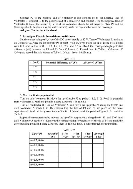
Connect P2 to the positive lead of Voltmeter B <strong>and</strong> connect P3 to the negative lead ofVoltmeter B. Connect P3 to the positive lead of Voltmeter A <strong>and</strong> connect P4 to the negative lead ofVoltmeter B. Note: the sensitivity level of the voltmeters should be set properly. Place P3 <strong>and</strong> P4(their tips should be also under the water surface) inside the tray <strong>and</strong> between the two rings.Ask your TA to check the circuit!2. Investigate <strong>Electric</strong> <strong>Potential</strong>-versus-DistanceSet the output voltage (V a −V b ) of the DC power supply to 12 V. Turn off Voltmeter B, <strong>and</strong> turnon Voltmeter A. Place the tip of probe P3 at point (r=1.5 in, =0). Place the tip of probe P4 at pointswith =0 <strong>and</strong> in turn with r′=1.7, 1.9, 2.1, 2.3, <strong>and</strong> 2.5 in. Read the correspondingly potentialdifference (V) between the P4 <strong>and</strong> P3 from Voltmeter C. Record them in Table 1. Calculate V/(r′−r) <strong>and</strong> record the ratio values in Table 1. (Note: 1 inch= 0.0254 m.)TABLE 1r′ (inch) <strong>Potential</strong> difference V (V) V /(r−r′) (V/m)1.71.92.12.32.53. Map the first equipotentialTurn on only Voltmeter B. Move the tip of probe P3 to point (r=1.5, =0). Read its potentialfrom Voltmeter B. Mark the point in Figure 2. Record it in Table 2.Turn off Voltmeter B. Turn on Voltmeter A, <strong>and</strong> move the tip probe P4 along the =90° lineuntil Voltmeter A reads 0 V. This means that the tips of P3 <strong>and</strong> P4 are place on the sameequipotential. Read out the y coordinate of the tip of P4 <strong>and</strong> mark the point in Figure 2. Record it inTable 2.Repeat the measurement by moving the tip of P4 respectively along the =180° <strong>and</strong> 270° linesuntil Voltmeter A reads 0 V. Read out the corresponding r coordinates of the tip of P4 <strong>and</strong> mark thecorresponding points in Figure 2. Record them in Table 2. Draw a curve through the four points.Tip of P3(r=1.5, =0)potential(V)TABLE 2r′ for r′ for=90° =180°r′ for=270°Averager & r′(r=1.7, =0)(r=1.9, =0)(r=2.1, =0)(r=2.3, =0)(r=2.5, =0)