Thin Lens and Image Formation
Thin Lens and Image Formation
Thin Lens and Image Formation

Create successful ePaper yourself
Turn your PDF publications into a flip-book with our unique Google optimized e-Paper software.
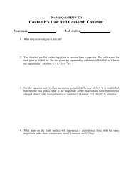
Pre-lab Quiz/PHYS 224<strong>Thin</strong> <strong>Lens</strong> <strong>and</strong> <strong>Image</strong> <strong>Formation</strong>Your name___________ Lab section_______________ __1. What do you investigate in this lab?2. The focal length of a bi-convex thin lens is 10 cm. To a real image with magnification of −2,what is the object distance p? What is the image distance q? Is the image upright or inverted?(Answer: p=15 cm, q=30 cm, inverted)3. The focal length of a bi-convex thin lens is 10 cm. The focal length of a convex-concave thinlens is -20 cm. If placing them in parallel <strong>and</strong> in close contact, what is the compound focal length?(Answer: 20 cm)4. For a red light beam, the refractive index of a thin lens is 1.510. For a blue light beam, therefractive index is 1.525. For the red light beam, the focal length of the thin lens is 20.0 cm. Forthe blue light beam, what is the corresponding focal length?(Answer: 19.4 cm)
Lab Report/PHYS 224<strong>Thin</strong> <strong>Lens</strong> <strong>and</strong> <strong>Image</strong> <strong>Formation</strong>Name_ _________ Lab section_______________ __ObjectiveIn this lab, you will measure the focal length of thin lens, use thin lens to form image <strong>and</strong>study the thin-lens equation, <strong>and</strong> observe the chromatic aberration of thin lens.Background<strong>Thin</strong>-lens equation Optics employs a variety of lenses for imageformation <strong>and</strong> spectroscopic measurement. In this lab, you will studyhow images are formed through diffraction by thin lenses. You will usetwo different kinds of thin lenses (Figure 1): two bi-convex lenses(converging) <strong>and</strong> a convex-concave lens (diverging).A lens is characterized by its focal points (F, F ́) <strong>and</strong> focal length(f). For a converging lens, if the incident rays are parallel with itsprinciple axis, the refracted rays by the lens converges at the focal point on the same side of thelens as the refracted rays. For a diverging lens, if the incident rays are parallel with its principleaxis, the refracted rays, when traced backward, converge at the focal point on the same side of thelens as the incident rays. The focal length, f, is thus positive for a converging lens <strong>and</strong> is negativefor a diverging lens; the magnitude of f is the distance between the focal point <strong>and</strong> the center of thelens.As shown in Figure 2, if an object is placed near the principle axis of a thin lens, the formedimage through diffraction by the thin lens is described by the thin-lens equation:1 1 1 . (1)p q fThe object distance, p, is the distance between the object <strong>and</strong> the center of the lens. The imagedistance, q, is the distance between the image <strong>and</strong> the center of the lens; q is positive for a realimage <strong>and</strong> negative for a virtual image. The magnification of the image is:image height qM . (2)object hei ght pThe image height is positive for an upright image <strong>and</strong> negative for an inverted image.Place two thin lenses (respectively with the focal length of f 1 <strong>and</strong> f 2 ) together such that theirprinciple axes coincide (so they are parallel) <strong>and</strong> they are in contact. This combination of thinlenses behaves also like a thin lens. Using Equation (1), it is straightforward to derive thecompound focal length as
1 1 1 . (3)f f1f2Converging lens Because a converging lens has positive focal length, following Equation(1) a converging lens can form both real <strong>and</strong> virtual images. If the object distance pf, Equation (1) leads to apositive q inferring a real image. Real images can directly project on a screen, enabling directmeasurement of q <strong>and</strong> M. Thus, selecting an appropriate p, one can form a real image, measure q,<strong>and</strong> use Equation (1) to calculate f.Method 1 Placing an object far away from the lens, p is much longer than f. Equation (1)leads to q≈f. Thus, a real image forms approximately at the focal point F ́. Placing an object near Fwith p>f but p≈f, Equation (1) leads to a very large q. Thus, a very large real image forms on ascreen placed far away. These are simple methods to approximately measure the focal length.Method 2 Placing the object at p=3f, Equation (1) leads to that q=1.5f.Method 3 Placing the object at p=2f, Equation (1) leads to that q=2f.Method 4 Placing the object p=1.5f, Equation (1) leads to that q=3f.Diverging lens Because the focal length of a diverging lens is negative, following Equation(1), it can form only virtual images which cannot directly project on screen. According to Equation(3), if combing a diverging lens with a converging lens with a shorter focal length, the compoundfocal length is however positive <strong>and</strong> can thus be measured directly. The focal length of thediverging lens can then be extracted.Chromatic aberration The focal length of a bi-convex thin lens placed in air follows thelens-maker’s equation1 1 1 ( n 1)( ) . (4)f R 1R 2n is the refractive index of the lens. R 1 is the radius of the curvature of its front surface <strong>and</strong> R 2 isthe radius of the curvature of its back surface. Because the refractive index is different at differentwavelengths, the focal length varies with the wavelength. For example, n is smaller for red lightthan for blue light. Thus, the focal length is longer for red light than for blue light, leading to thechromatic aberration for the lens.
EXPERIMENTIn this lab, the object, lens holder, <strong>and</strong> screen are placed on track <strong>and</strong> can move along the track.p <strong>and</strong> q are determined by reading their positions from the attached rule on the track.Procedures1. Measure the object sizeUse the calibrator to measure the object height. Recommend to measure the height of thearrow, h. Record it in Table 1.2. Measure the focal length of the first bi-convex lens(Method 1) Place the lens on the lens holder. Move the screen to the opposite end of the track.Move the lens holder until you can see the sharpest image on the screen. Using the rule, determinethe image distance between the lens holder <strong>and</strong> the screen which is approximately the focal length,f 1 . Record it in Table 1. Move the lens holder towards the object; when their distance is about f 1 , youshould see a very large <strong>and</strong> sharp image on the screen.(Method 2) Move the lens holder away from the object to make p≈3f 1 . Then, move the screenuntil you can see the sharpest image on the screen. Using the rule, determine the image distance qbetween the lens holder <strong>and</strong> the screen. Record it in Table 1. Use the calibrator to measure the heightof the arrow on the screen, h ́. Be careful with the sign of h ́.(Method 3) Move the lens holder towards the object to make p≈2f 1 . Then, move the screenuntil you can see the sharpest image on the screen. Using the rule, determine the image distance qbetween the lens holder <strong>and</strong> the screen. Record it in Table 1. Use the calibrator to measure the heightof the arrow on the screen.(Method 4) Move the lens holder towards the object to make p≈1.5f 1 . Then, move the screenuntil you can see the sharpest image on the screen. Using the rule, determine the image distance qbetween the lens holder <strong>and</strong> the screen. Record it in Table 1. Use the calibrator to measure the heightof the arrow on the screen.Using Equation (1) <strong>and</strong> the p <strong>and</strong> q data from Methods 2-4, calculateTABLE 1 <strong>Lens</strong> 1p (cm) q (cm) f 1 (cm) M=−q/p object height image height M=h ́/h(~ ∞)(~3f 1 )(~2f 1 )(~1.5f 1 )Using Equation (1) <strong>and</strong> the p <strong>and</strong> q data from Methods 2-4, calculate the corresponding focallength <strong>and</strong> record in Table 1. Calculate their mean value <strong>and</strong> record it here:f1Using the p <strong>and</strong> q data from Methods 2-4, calculate M= -q/p <strong>and</strong> record in Table 1.Using the h <strong>and</strong> h ́ data from Methods 2-4, calculate M= h ́/ h <strong>and</strong> record in Table 1.
3. Measure the chromatic aberration of the first bi-convex lensMove the lens holder towards the object to make p≈1.5f 1 . Now, place the red filter on theobject, <strong>and</strong> move the screen until you can see the sharpest image on the screen. Using the rule,determine the image distance q between the lens holder <strong>and</strong> the screen. Record it in Table 2.Now, place the blue filter on the object, <strong>and</strong> move the screen until you can see the sharpestimage on the screen. Using the rule, determine the image distance q between the lens holder <strong>and</strong> thescreen. Record it in Table 2.Using Equation (1) <strong>and</strong> the p <strong>and</strong> q data, calculate the corresponding focal length <strong>and</strong> record inTable 2.TABLE 2 Chromatic Aberrationp (cm) q (cm) f (cm)Red filterBlue filter4. Measure the focal length of the Plano-convex lens (converging)Place the lens on the lens holder. Move the object <strong>and</strong> the screen to the opposite ends of therule. Move the lens holder until you can see the sharpest image on the screen. Using the rule,determine the image distance between the lens holder <strong>and</strong> the screen which is approximately thefocal length, f 2 . (Method 3) Move the lens holder towards the object to make p≈2f 2 . Then, move thescreen until you can see the sharpest image on the screen. Using the rule, determine the imagedistance q between the lens holder <strong>and</strong> the screen.Record p = q=Using Equation (1) <strong>and</strong> the p <strong>and</strong> q data calculate the focal lengthf25. Measure the compound focal length for the two converging lensesCarefully place the bi-convex lens <strong>and</strong> the plano-convex lens (in contact <strong>and</strong> in parallel) on the2 f1f2lens holder. Move the lens holder towards the object to make p . Then, move the screenf1 f2until seeing the sharpest image. Determine the image distance q between the lens holder <strong>and</strong> thescreen.Record p = q=Using Equation (1) <strong>and</strong> the p <strong>and</strong> q data, calculate the compound focal length f 1&2 =6. Measure the compound focal length of the bi-convex lens & the plano-concave(diverging) lensPlace the bi-convex lens <strong>and</strong> the plano-concave (in contact <strong>and</strong> in parallel) on the lens holder.Move the lens holder towards the object until p 3 f1. Then, move the screen until seeing thesharpest image. Determine the image distance q between the lens holder <strong>and</strong> the screen.Record p = q=Using Equation (1), calculate the compound focal length: f 1&3 =Using Equation (3), f1, <strong>and</strong> f 1&3 , calculate the focal length of the diverging lens: f 3 =
Questions1. In procedure 2, are all the images upright or inverted? What is the direction of the horizontalarrow on the screen?2. Using the first bi-convex lens to form a magnified real image, in what range should the objectdistance be?3. Using Equation (4) <strong>and</strong> the data in Table 2, calculate the ratio of the refractive index of the lensbetween the red light <strong>and</strong> the blue light.f1f24. Calculate <strong>and</strong> compare it with the measured f 1&2 . Calculate their difference inf1 f2percentage. Will f 1&2 change if you switch the position of the two lenses in the combination?5. For the combination of the diverging lens <strong>and</strong> the converging lens, what is the compound focallength? Can you use this combination to measure the focal length of the diverging lens?