
You also want an ePaper? Increase the reach of your titles
YUMPU automatically turns print PDFs into web optimized ePapers that Google loves.
Installation, Operation and<br />
Maintenance Manual<br />
Adjusta Adjustable Adjusta ble Fr Frequenc Fr equenc equency equenc y Dr Driv Dr iv ive iv<br />
1703 1703 Ser Series Ser ies 7.5 7.5 thr through thr ough 100 100 Amp<br />
Amp<br />
9/00 Revision A 23-6088-00
DANGER ANGER<br />
Rotating shafts and electrical equipment can be hazardous. Therefore, it is strongly<br />
recommended that all electrical work conform to the National Electrical Code and all<br />
local regulations. Installation, start-up and maintenance should be performed only by<br />
qualified personnel.<br />
Factory recommended procedures, included in this manual, should be followed. Always<br />
disconnect electrical power before working on the unit.<br />
Although shaft couplings or belt drives are generally not furnished by the manufacturer,<br />
rotating shafts, couplings and belts must be protected with securely mounted metal<br />
guards that are of sufficient thickness to provide protection against flying particles such<br />
as keys, bolts and coupling parts. Refer to OSHA Rules and Regulations paragraph<br />
1910.219 for guards on mechanical power transmission apparatus. Even when the motor<br />
is stopped, it should be considered “alive” as long as its controller is energized. Keep<br />
hands away from the output shaft until the motor has completely stopped and power is<br />
disconnected from the controller.<br />
Motor control equipment and electronic controls are connected to hazardous line voltages. When<br />
servicing drives and electronic controls, there will be exposed components at or above line potential.<br />
Extreme care should be taken to protect against shock Stand on an insulating pad and make it a habit to<br />
use only one hand when checking components. Always work with another person in case of an<br />
emergency. Disconnect power whenever possible to check controls or to perform maintenance. Be sure<br />
equipment is properly grounded. Wear safety glasses whenever working on electronic control or rotating<br />
equipment.<br />
Federal Federal Comm Communications Comm unications Commission<br />
Commission<br />
Radio Radio Frequenc Frequency Frequenc y Interf Interference Interf erence Statement<br />
Statement<br />
NOTE: This equipment has been tested and found to comply with the limits for a Class A<br />
digital device, pursuant to Part 15 of the FCC Rules. These limits are designed to provide<br />
reasonable protection against harmful interference when the equipment is operated in a<br />
commercial environment. This equipment generates, uses and can radiate radio<br />
frequency energy and, if not installed and used in accordance with the instruction<br />
manual, may cause harmful interference to radio communications. Operation of this<br />
equipment in a residential area is likely to cause harmful interference in which case the<br />
user will be required to correct the interference at his own expense. The user is cautioned<br />
that any changes or modifications not expressly approved by the party responsible for<br />
compliance could void the user's authority to operate the equipment.<br />
Since improvements are continually being made, the enclosed data is subject to change<br />
without notice. Any drawings are for reference only, unless certified. For additional<br />
information contact Graham Service Department.<br />
Copyright © 1998, Graham, Division of <strong>Danfoss</strong> Inc.
Table able of of Contents<br />
Contents<br />
ii<br />
Page<br />
Page<br />
General ..................................................................................................... 1<br />
Receipt of Shipment .................................................................................... 1<br />
Storage ..................................................................................................... 1<br />
Handling ..................................................................................................... 1<br />
Section Section 1. 1. Installation<br />
Installation<br />
Installation<br />
1.1 Mounting .................................................................................... 1<br />
1.2 Temperature and Ventilation .................................................... 1<br />
Section Section Section 2. 2. Wiring<br />
Wiring<br />
2.1 Input Voltage .............................................................................. 4<br />
2.2 Ground Connections ................................................................... 4<br />
2.3 Input Disconnect and Input Fuses ............................................ 4<br />
2.4 Isolation Transformer ................................................................ 4<br />
2.5 Input Wiring ............................................................................... 7<br />
2.6 Output Wiring ............................................................................ 7<br />
2.7 Output/Motor Disconnect .......................................................... 7<br />
2.8 Conduit Entry ............................................................................. 7<br />
2.9 Control Circuit Wiring ............................................................... 7<br />
2.10 Remote Follower Connections ................................................... 7<br />
2.11 Run and Fault Contacts ............................................................. 8<br />
2.12 Remote Run/Stop ........................................................................ 8<br />
2.13 Remote Safety Interlock............................................................. 8<br />
2.14 Speed Signal Output .................................................................. 8<br />
2.15 Torque Specifications ................................................................. 9<br />
Drive Currents, and Isolation Transformer Sizing Table ........ 9<br />
Section Section 3. 3. Operator Operator Controls<br />
Controls<br />
3.1 Switches .....................................................................................10<br />
3.1.1 Start Select Switches ................................................................10<br />
3.1.2 Speed Select Switches ...............................................................10<br />
3.1.3 Speed Switches ..........................................................................10<br />
3.1.4 Meter Select Switch ..................................................................10<br />
3.2 Standard Option Switches ........................................................11<br />
3.2.1 Drive Input Disconnect Switch ................................................11<br />
3.2.2 Bypass Disconnect Switch ........................................................11<br />
3.2.3 Main Disconnect Switch ...........................................................11<br />
3.2.4 Drive/Off/Line/Transfer Switch ................................................11<br />
3.2.5 Drive/Off/Line/Test Transfer Switch........................................12<br />
3.2.6 Interlocked Contactor Bypass...................................................12<br />
3.2.7 Transfer Switch Motor Selection ..............................................13<br />
3.2.8 Contactor Motor Selection ........................................................13
Section Section 4. 4. External External Drive Drive Status Status Indicators Indicators<br />
Page<br />
Page<br />
4.1 Power On ...................................................................................14<br />
4.2 Ready .........................................................................................14<br />
4.3 Run .............................................................................................14<br />
4.4 @ .................................................................................................14<br />
4.5 Rev..............................................................................................14<br />
4.6 Fault ...........................................................................................14<br />
4.7 OL ...............................................................................................14<br />
4.8 PL ...............................................................................................14<br />
4.9 OT ...............................................................................................14<br />
4.10 OC ..............................................................................................14<br />
4.11 UV ..............................................................................................15<br />
4.12 OV ..............................................................................................15<br />
4.13 GF ...............................................................................................15<br />
4.14 EXT ............................................................................................15<br />
4.15 Lamp Test/High Voltage ...........................................................15<br />
4.16 Meter Display Indicators ..........................................................15<br />
4.17 MIN MAX..........................................................................15<br />
Section Section 5. 5. 5. Internal Internal Internal Drive Drive Drive Status Status Indicators<br />
Indicators<br />
5.1 BUS PWR ...................................................................................16<br />
5.2 COMM P.S. ................................................................................16<br />
5.3 COMM DRIVE...........................................................................16<br />
5.4 COND DRIVE ............................................................................16<br />
5.5 RUN CMD..................................................................................16<br />
Section Section 6. 6. Internal Internal Internal Adjustments<br />
Adjustments<br />
Adjustments<br />
6.1 Offset and Gain .........................................................................19<br />
6.2 Minimum and Maximum Speed ...............................................19<br />
6.3 Maximum Extended Speed .......................................................19<br />
6.4 Overload .....................................................................................19<br />
6.5 Current Limit ............................................................................19<br />
6.6 I Comp ........................................................................................19<br />
6.7 Walking Frequency ...................................................................20<br />
6.8 V/HZ Cal (Optional) ..................................................................20<br />
6.9 Standard Calibration Settings ..................................................20<br />
6.10 P1, P2, P3 and P4 ......................................................................22<br />
6.11 P5, P6 and P7 ............................................................................22<br />
Section Section Section 7. 7. 7. Internal Internal Internal Switches Switches<br />
Switches<br />
7.1 Switch SW1 ................................................................................23<br />
7.1.1 A0, A1 and A2 ............................................................................23<br />
7.1.2 D0, D1, and D2 ..........................................................................23<br />
7.1.3 FCR ............................................................................................23<br />
7.1.4 OL ...............................................................................................23<br />
7.2 Switch SW2 ................................................................................23<br />
7.2.1 EXTR ..........................................................................................23<br />
7.2.2 OVR ............................................................................................24<br />
7.2.3 UVR ............................................................................................24<br />
7.2.4 OCR ............................................................................................24<br />
7.2.5 PLR ............................................................................................24<br />
7.2.6 HI-TORQUE ..............................................................................24<br />
7.2.7 EXT SPD ....................................................................................24<br />
7.2.8 4-20mA .......................................................................................24<br />
iii
iv<br />
Page<br />
Page<br />
7.3 SWITCH SW3 ............................................................................25<br />
7.3.1 COAST .......................................................................................25<br />
7.3.2 REVERSE ..................................................................................25<br />
7.3.3 60HZ ...........................................................................................25<br />
7.3.4 Output Voltages.........................................................................25<br />
7.4 Standard Switch Configuration ................................................26<br />
Section Section 8. 8. Start-up Start-up and and Calibration Calibration Procedures<br />
Procedures<br />
8.1 Pre-Check Sequence ..................................................................27<br />
8.2 Calibration Procedure ...............................................................27<br />
Section Section 9. 9. Service Service Information<br />
Information<br />
9.1 Introduction ...............................................................................29<br />
9.2 Description of Operation ...........................................................29<br />
9.3 Troubleshooting .........................................................................29<br />
9.4 Minimum Recommended Test Equipment ..............................31<br />
9.5 Diode, Transistor and SCR Test ...............................................31<br />
9.5.1 Diode, Transistor and SCR Testing..........................................31<br />
9.6 Doide, Transistor and SCR Replacement.................................33<br />
9.6.1 Input SCR Modules ...................................................................33<br />
9.6.2 Output SCR Modules ................................................................33<br />
9.6.3 Output Diode Bridge .................................................................33<br />
9.6.4 Free-Wheeling Diode .................................................................33<br />
9.6.5 Conduction/Commutation Transistor Module .........................33<br />
9.7 Power Up Sequence ...................................................................33<br />
9.8 Power Supply on the Control Board .........................................33<br />
9.9 Output Checks ...........................................................................34<br />
Troubleshooting Flow Chart ......................................................................35<br />
List List of of of Illustrations<br />
Illustrations<br />
Typical 1703 Series ...................................................................................... 3<br />
Typical Older 1703 Series, 21 Amps and Below, Customer Connections. 5<br />
Typical 1703 Series, Customer Connections .............................................. 6<br />
Control Board .............................................................................................17<br />
Control Chip Board, drawing.....................................................................18<br />
Control Chip Board, photo .........................................................................21<br />
Display Board, drawing .............................................................................22<br />
Remote Speed Signal Calibration on Control Board ................................28<br />
Control Board Swung Open .......................................................................30<br />
Input/Output SCRs ....................................................................................31<br />
Output Diode Bridge Module .....................................................................32<br />
Conduction/Commutation Transistor Module ..........................................32
GENERAL<br />
GENERAL<br />
This operation and maintenance manual provides the<br />
necessary installation, adjustment and maintenance<br />
procedures for the 7.5 through 100 amp Graham Series<br />
1703 adjustable frequency drives. Since these instructions<br />
are general, problems may occur which are<br />
beyond the scope of the manual. If further information<br />
is desired, please contact Graham for assistance.<br />
NOTE: As-built schematics and made-to-order equipment<br />
operation supersede the instructions in this<br />
manual.<br />
Although every precaution has been taken in the design<br />
of the drive to ensure reliability under extreme<br />
operating conditions, it is possible to damage the<br />
equipment through misuse or misapplication. Therefore,<br />
this instruction manual should be carefully reviewed<br />
before installing and operating the equipment.<br />
RECEIPT RECEIPT RECEIPT OF OF SHIPMENT<br />
SHIPMENT<br />
SHIPMENT<br />
When the drive is received, it should be compared<br />
with the packing slip to be sure that everything is received.<br />
Any damages or shortages should be reported<br />
immediately to the carrier who transported the drive.<br />
If necessary, contact Graham for assistance, referring<br />
to the order number, equipment description and serial<br />
number.<br />
STORAGE<br />
STORAGE<br />
For long periods of storage, the drive must be covered<br />
to prevent corrosion and contamination. It must be<br />
stored in a clean, dry location between -40 o F (-40 o C)<br />
and 185 o F (+85 o C). The relative humidity should not<br />
exceed 95%. The drive should be checked periodically<br />
to ensure that no condensation has formed. After storage,<br />
again check that it is dry before applying power.<br />
Some of the electrolytic capacitors used in the drive<br />
are subject to the relaxation of an internal formed oxide<br />
film after long periods of storage and may require<br />
reforming prior to applying power. If the drive has<br />
been stored for over 18 months, Graham should be<br />
contacted for a determination as to whether a reforming<br />
procedure is necessary.<br />
HANDLING<br />
HANDLING<br />
Care should be taken to prevent damage when moving<br />
the drive. The drive should be lifted using hooks or<br />
clevis pins through the lifting holes in the mounting<br />
rails.<br />
1<br />
�<br />
�������<br />
DO DO NOT NOT NOT ATTEMPT ATTEMPT TO TO LIFT LIFT OR<br />
OR<br />
SUPPORT SUPPORT SUPPORT THE THE DRIVE DRIVE BY BY THE THE<br />
THE<br />
ENCLOSURE ENCLOSURE OR OR THE THE INTERNAL<br />
INTERNAL<br />
COMPONENTS.<br />
COMPONENTS.<br />
SECTION SECTION 1. 1. INST INSTALLA<br />
INST ALLA ALLATION<br />
ALLA TION<br />
1.1 1.1 MOUNTING<br />
MOUNTING<br />
The 1703 Series drives are all designed to be wall<br />
mounted. If they must be floor mounted, a floor stand<br />
can be supplied. Assemble the base struts to the vertical<br />
rectangular section struts using the support brackets<br />
supplied. The floor stand must be firmly anchored<br />
to the floor or wall for stability. Attach the drive to the<br />
vertical rectangular section struts using the spring<br />
loaded fasteners provided. Leave the enclosure closed<br />
until it is time to wire the drive.<br />
The following minimum clearances are recommended:<br />
Thru Thru Thru 28 28 thru thru 100<br />
100<br />
21 21 amp amp 77 77 amp amp amp amp<br />
amp<br />
To bottom of enclosure 6" 6" 6"<br />
To right side of enclosure 6" 10" 15"<br />
To left side of enclosure 6" 10" 15"<br />
To top of enclosure 3" 3" 3"<br />
To front of enclosure 19" 19" 19"<br />
To back of enclosure Mounting rails supply<br />
necessary clearance<br />
The current rating of the drive is shown on the name<br />
plate on the inside of the door.<br />
These clearances are for access, air flow and conduit<br />
entry and must be maintained.<br />
All conduit and wiring must enter through the top of<br />
the enclosure.<br />
Do not remove the conduit entry plate during transportation<br />
or mounting. See Section 2 for details on<br />
wiring the drive.<br />
1.2 1.2 TEMPERATURE TEMPERATURE AND<br />
AND<br />
VENTILATION<br />
VENTILATION<br />
All electronic equipment is susceptible to failure if operated<br />
in ambient temperatures outside of its rating.<br />
The operating temperature range for this Graham<br />
drive is -20 o C to 40 o C (-4 o F to 104 o F). The drive should<br />
not be operated outside these extremes.
1. If the ambient will be below -20 o C, Graham<br />
should be notified so a space heater can be provided<br />
inside the enclosure.<br />
2. If the ambient will exceed 40 o C, a source of<br />
cooling will be required.<br />
3. If the drive will be operated intermittently in<br />
cold and/or humid conditions, precautions<br />
must be taken to prevent condensation from<br />
forming when the drive is off. A thermostatically<br />
controlled temperature control should be<br />
installed to maintain acceptable temperature<br />
and moisture control. Consult Graham for further<br />
recommendations.<br />
1703 Series drives are cooled by fan(s) drawing air<br />
through slots in the standard enclosure and across the<br />
heatsink. The slots must never be restricted in any<br />
way. The slots were covered for shipping. The covering<br />
material must be removed before operating the<br />
drive.<br />
�<br />
������<br />
FLAMMABLE FLAMMABLE MATERIALS MATERIALS MATERIALS MUST<br />
MUST<br />
BE BE KEPT KEPT AWAY AWAY FROM FROM THE THE EN-<br />
EN-<br />
CLOSURE.<br />
CLOSURE.<br />
The drive must be installed in a clean, dry environment<br />
unless special enclosure provisions are provided.<br />
Periodically, the drive should be cleaned using a vacuum<br />
cleaner and a soft, long-bristled brush. Lightly<br />
brush the dust from the drive components with the<br />
brush and use the vacuum cleaner to remove the dust<br />
as it falls. If available, clean dry compressed air at a<br />
maximum pressure of 50 psi (3.4 atmospheres) may be<br />
used to blow dust from the drive.<br />
�<br />
�������<br />
DO DO NOT NOT USE USE A A VACUUM VACUUM CLEANER<br />
CLEANER<br />
DIRECTLY DIRECTLY ON ON THE THE ELECTRONIC<br />
ELECTRONIC<br />
COMPONENTS.<br />
COMPONENTS.<br />
COMPONENTS.<br />
2<br />
�<br />
������<br />
ALWAYS ALWAYS REMOVE REMOVE THE THE THE INCOMING<br />
INCOMING<br />
INCOMING<br />
POWER POWER TO TO THE THE ENCLOSURE ENCLOSURE BE-<br />
BE-<br />
FORE FORE OPENING OPENING THE THE DOOR. DOOR. DOOR. WAIT WAIT<br />
WAIT<br />
UNTIL UNTIL UNTIL THE THE THE “BUS “BUS “BUS POWER” POWER” LED<br />
LED<br />
EXTINGUISHES EXTINGUISHES BEFORE BEFORE TOUCH-<br />
TOUCH-<br />
ING ING ANY ANY INTERNAL INTERNAL INTERNAL COMPO-<br />
COMPO-<br />
NENTS. NENTS. THEN, THEN, USING USING A A VOLTME-<br />
VOLTME-<br />
TER TER ON ON THE THE 100 100 VOLT VOLT DC DC SCALE, SCALE,<br />
SCALE,<br />
MEASURE MEASURE THE THE VOLTAGE VOLTAGE FROM<br />
FROM<br />
JACK JACK J2 J2 TERMINAL TERMINAL 9 9 (+) (+) (+) TO TO JACK<br />
JACK<br />
J1 J1 TERMINAL TERMINAL 6 6 6 (-) (-) ON ON THE THE CON-<br />
CON-<br />
TROL TROL BOARD BOARD TO TO TO VERIFY VERIFY THAT<br />
THAT<br />
ALL ALL VOLTAGES VOLTAGES HAVE HAVE DISSI-<br />
DISSI-<br />
PATED PATED PATED BEFORE BEFORE SERVICING SERVICING THE<br />
THE<br />
DRIVE.<br />
DRIVE.
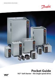
TYPICAL 1703 SERIES<br />
3<br />
Conduit Entry Plate<br />
Mounting Rail<br />
Lifting Holes<br />
Mounting Holes<br />
Air Vents<br />
Drive/Off/Line/Test Switch<br />
(optional)<br />
Display Meter and Panel<br />
Operator Control Panel
SECTION SECTION 2. 2. 2. WIRING<br />
WIRING<br />
2.1 2.1 INPUT INPUT VOLTAGE<br />
VOLTAGE<br />
The drive can be setup to operate on a broad range of<br />
voltages. It was factory set to operate on the voltage<br />
shown on the nameplate. Check the drive nameplate<br />
for the proper input and output voltages before wiring<br />
the drive. If the input voltage shown on the nameplate<br />
is different than the voltage available, the drive may<br />
be changed by reconnecting the leads from the control<br />
transformer as shown below.<br />
�<br />
�������<br />
CONTACT CONTACT GRAHAM GRAHAM BEFORE<br />
BEFORE<br />
CHANGING CHANGING THE THE INPUT INPUT VOLTAGE<br />
VOLTAGE<br />
CONNECTION.<br />
CONNECTION.<br />
On drives rated 21 amps or less, the P, S, and N connection<br />
taps are located either on the power board or<br />
on the snubber board. On all drives above 21 amps,<br />
the connection taps are on the snubber board.<br />
H1 through H8 are the transformer taps. They are<br />
color coded as shown below.<br />
Transformer Wire<br />
Line H1 H2 H3 H4 H5 H6 H7 H8<br />
Voltage White Red OrangeYellowGreen Blue Purple Grey<br />
200/208 P3 P1 N1 P4 P2 N2 N3 N4<br />
230 P3 N1 P1 P4 N2 P2 N3 N4<br />
380 P3 N1 S1 S2 N2 N3 N4 P1<br />
415 P3 S2 N1 S1 P1 N2 N3 N4<br />
460 P3 N1 S1 S2 N2 P1 N3 N4<br />
575* P3 N1 S1 S2 N2 N3 P1 N4<br />
*See warning below<br />
�<br />
�������<br />
A A DRIVE DRIVE NAMEPLATED NAMEPLATED NAMEPLATED FOR<br />
FOR<br />
460VAC 460VAC OR OR LESS LESS MUST MUST NOT NOT NOT BE<br />
BE<br />
RECONNECTED RECONNECTED FOR FOR 575VAC 575VAC IN-<br />
IN-<br />
PUT PUT VOLTAGE. VOLTAGE. DAMAGE DAMAGE TO TO TO THE<br />
THE<br />
DRIVE DRIVE POWER POWER POWER COMPONENTS<br />
COMPONENTS<br />
CAN CAN RESULT RESULT FROM FROM IMPROPER<br />
IMPROPER<br />
VOLTAGE VOLTAGE VOLTAGE CONNECTIONS.<br />
CONNECTIONS.<br />
A drive nameplated for 575 V AC may be reconnected<br />
for any of the lower voltages. Some 575 V AC drives<br />
rated 21 amps or less will have only the H1, H3, H4<br />
and H7 connections. Connect these as shown in the<br />
table above.<br />
4<br />
�<br />
�������<br />
REDUCING REDUCING THE THE INPUT INPUT VOLTAGE<br />
VOLTAGE<br />
WILL WILL REDUCE REDUCE THE THE THE HORSEPOWER<br />
HORSEPOWER<br />
HORSEPOWER<br />
CAPABILITY CAPABILITY OF OF THE THE DRIVE.<br />
DRIVE.<br />
Selecting different input and output voltages may<br />
damage the drive or motor or both and will result in<br />
improper operation of the system.<br />
2.2 2.2 GROUND GROUND CONNECTIONS<br />
CONNECTIONS<br />
A yellow and green grounding terminal (4TB1) is provided<br />
for a dedicated ground wire connection. All provisions<br />
of the National Electrical Code and local codes<br />
must be followed.<br />
�<br />
�������<br />
CONDUIT CONDUIT GROUND GROUND AND AND DAISY<br />
DAISY<br />
CHAIN CHAIN GROUNDING GROUNDING ARE ARE ARE NOT NOT NOT AD-<br />
AD-<br />
EQUATE. EQUATE. COLD COLD COLD WATER WATER PIPE PIPE PIPE CON-<br />
CON-<br />
NECTIONS NECTIONS ARE ARE ARE NOT NOT NOT ADEQUATE. ADEQUATE. A<br />
A<br />
SEPARATE SEPARATE GROUNDING GROUNDING GROUNDING WIRE<br />
WIRE<br />
MUST MUST BE BE RUN RUN TO TO AVOID AVOID POSSIBLE<br />
POSSIBLE<br />
ELECTRICAL ELECTRICAL NOISE NOISE PROBLEMS<br />
PROBLEMS<br />
AND AND POTENTIAL POTENTIAL SAFETY SAFETY SAFETY HAZARDS.<br />
HAZARDS.<br />
2.3 2.3 INPUT INPUT DISCONNECT DISCONNECT AND AND INPUT<br />
INPUT<br />
FUSES<br />
FUSES<br />
The drive may be supplied with or without an input<br />
disconnect and input fuses. Size the input disconnect<br />
and fuses to handle the Drive Input Current rating<br />
shown in the table on page 9. Input fuses are not required<br />
to protect the drive. Special fast acting fuses<br />
should not be used.<br />
2.4 2.4 ISOLATION ISOLATION TRANSFORMER<br />
TRANSFORMER<br />
TRANSFORMER<br />
If an isolation transformer is used, size it from the<br />
table on page 9.<br />
If an isolation transformer is used, the National Electrical<br />
Code requires that an input disconnect must be<br />
placed between the transformer secondary and the<br />
drive input.<br />
�<br />
�������<br />
TO TO AVOID AVOID DAMAGE DAMAGE TO TO THE THE DRIVE,<br />
DRIVE,<br />
DO DO NOT NOT OPEN OPEN OR OR CLOSE CLOSE CLOSE ANY ANY DIS-<br />
DIS-<br />
CONNECT CONNECT ON ON THE THE PRIMARY PRIMARY SIDE<br />
SIDE<br />
OF OF THE THE TRANSFORMER TRANSFORMER UNTIL UNTIL AF-<br />
AF-<br />
TER TER THE THE DISCONNECT DISCONNECT DISCONNECT ON ON THE<br />
THE<br />
SECONDARY SECONDARY SECONDARY SIDE SIDE SIDE IS IS OPENED. OPENED.<br />
OPENED.
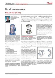
4TB4 Customer Terminal Strip<br />
F1 and F2 Fuses<br />
Older drives were built as shown here. Newer drives of<br />
21 amps or below do not have a separate power board.<br />
The customer connections for these drives and all<br />
drives larger than 21 amps are shown on page 6.<br />
TYPICAL OLDER 1703 SERIES, MODELS 21 AMPS AND BELOW<br />
Customer Connections<br />
5<br />
Input Power Line Terminal Strip<br />
Motor Terminal Strip<br />
Drive/Off/Line/Test Switch<br />
(optional)
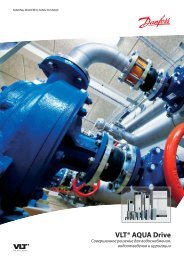
4TB4 Customer Terminal Strip<br />
Input Power<br />
Line Terminals<br />
Input from Motor<br />
Starter Terminals<br />
(optional)<br />
Motor Terminals<br />
TYPICAL 1703 SERIES<br />
Customer Connections<br />
6<br />
See page 5 for older drives of 21 amps or less.<br />
Drive/Off/Line/Test Switch<br />
(optional)
2.5 2.5 INPUT INPUT WIRING<br />
WIRING<br />
Input wire types and sizes must be selected based<br />
upon conformance with the National Electrical Code<br />
and all local codes and restrictions. See table on page 9<br />
for power wiring and ground wiring sizes.<br />
2.6 2.6 OUTPUT OUTPUT WIRING<br />
WIRING<br />
Motor wiring types and sizes must be selected based<br />
upon conformance with the National Electrical Code<br />
and all local codes and restrictions. See table on page 9<br />
for power wiring and ground wiring sizes.<br />
�<br />
�������<br />
DO DO NOT NOT INSTALL INSTALL MOTOR MOTOR WIRING<br />
WIRING<br />
IN IN THE THE SAME SAME CONDUIT CONDUIT OR OR OR RACE-<br />
RACE-<br />
WAY WAY WAY WITH WITH WITH OTHER OTHER OTHER WIRING. WIRING. WIRING. IM-<br />
IM-<br />
PROPER PROPER INSTALLATION INSTALLATION OF OF THE THE<br />
THE<br />
MOTOR MOTOR MOTOR WIRING WIRING CAN CAN CAUSE<br />
CAUSE<br />
ELECTRICAL ELECTRICAL NOISE NOISE NOISE IN IN IN THE<br />
THE<br />
POWER POWER DISTRIBUTION DISTRIBUTION WIRING.<br />
WIRING.<br />
2.7 2.7 OUTPUT/MOTOR OUTPUT/MOTOR DISCONNECT<br />
DISCONNECT<br />
It is recommended that any device which can disconnect<br />
the motor from the output of the drive be interlocked<br />
to the emergency shutdown circuits of the<br />
drive. This will provide an orderly shutdown if the disconnecting<br />
device is opened while the drive is in operation.<br />
Interlock contacts should be installed in series<br />
with terminals 5 and 6 of terminal strip 4TB4.<br />
�<br />
�������<br />
CLOSING CLOSING A A MOTOR MOTOR DISCONNECT<br />
DISCONNECT<br />
SWITCH SWITCH WHILE WHILE THE THE DRIVE DRIVE DRIVE IS<br />
IS<br />
RUNNING RUNNING CAN CAN CAUSE CAUSE NUISANCE<br />
NUISANCE<br />
NUISANCE<br />
FAULT FAULT TRIPS.<br />
TRIPS.<br />
2.8 2.8 CONDUIT CONDUIT ENTRY ENTRY<br />
ENTRY<br />
All 1703 model drives are designed for conduit entry<br />
at the top of the enclosure. A removable conduit entry<br />
plate is provided for ease of installation.<br />
1. Mark the location of the conduit entries for<br />
input power, motor wiring and control wiring<br />
on the conduit entry plate.<br />
2. Remove the conduit entry plate.<br />
3. Drill the conduit entry holes in the plate.<br />
4. Reinstall the plate on the drive and connect<br />
the conduit to the plate.<br />
7<br />
�<br />
�������<br />
DO DO NOT NOT NOT DRILL, DRILL, SAW, SAW, FILE FILE FILE OR<br />
OR<br />
PERFORM PERFORM ANY ANY ANY OPERATION OPERATION OPERATION ON<br />
ON<br />
THE THE DRIVE DRIVE DRIVE ENCLOSURE ENCLOSURE OR OR CON-<br />
CON-<br />
DUIT DUIT ENTRY ENTRY PLATE PLATE WHILE WHILE THEY THEY<br />
THEY<br />
ARE ARE ON ON THE THE DRIVE. DRIVE. METAL METAL FIL-<br />
FIL-<br />
INGS INGS AND AND OTHER OTHER FOREIGN FOREIGN MA-<br />
MA-<br />
TERIALS TERIALS WHICH WHICH CONTAMINATE<br />
CONTAMINATE<br />
THE THE DRIVE DRIVE DRIVE CAN CAN CAUSE CAUSE DAMAGE<br />
DAMAGE<br />
AND AND MAY MAY VOID VOID VOID WARRANTY WARRANTY COV- COV-<br />
COV-<br />
ERAGES.<br />
ERAGES.<br />
2.9 2.9 CONTROL CONTROL CIRCUIT CIRCUIT CIRCUIT WIRING<br />
WIRING<br />
Control circuit wiring connections (low voltage DC<br />
and 120 volt AC) are terminated on terminal strip<br />
4TB4. Shielded cable should be installed for all low<br />
voltage DC control signal wiring. The shield of the<br />
cable must be connected to the negative terminal for<br />
the control signal. Do not connect the shield at the<br />
other end of the cable. Insulate the shield so that no<br />
electrical connection is made at the other end of the<br />
cable.<br />
�<br />
�������<br />
NEVER NEVER CONNECT CONNECT THE THE THE SHIELD SHIELD TO<br />
TO<br />
EARTH EARTH EARTH GROUND.<br />
GROUND.<br />
NEVER NEVER CONNECT CONNECT THE THE SHIELD- SHIELD-<br />
SHIELD-<br />
ING ING WIRE WIRE OF OF OF A A SHIELDED SHIELDED CABLE<br />
CABLE<br />
AT AT BOTH BOTH ENDS. ENDS.<br />
ENDS.<br />
2.10 2.10 REMOTE REMOTE FOLLOWER<br />
FOLLOWER<br />
CONNECTIONS<br />
CONNECTIONS<br />
For automatic speed tracking, the drive is supplied<br />
with an interface circuit for inputs from a system control<br />
panel. The input signal wiring is terminated to<br />
terminals 13(+) and 14(-) of terminal strip 4TB4.<br />
These connections are used for both DC voltage and<br />
current input signals. Selection of the type of follower<br />
to be used is made by the position of the SW2 switch<br />
labeled 4-20mA as shown below.<br />
Signal Signal Range Range SW2 SW2 SW2 (4-20mA)<br />
(4-20mA)<br />
Current Input 0 to +40mA On<br />
Voltage Input 0 to +40VDC Off<br />
The voltage and current input circuits are electrically<br />
isolated from chassis ground by 1,000 ohms.
�<br />
�������<br />
APPLICATIONS APPLICATIONS REQUIRING<br />
REQUIRING<br />
REQUIRING<br />
MORE MORE THAN THAN THAN 24 24 V V DC DC ISOLATION<br />
ISOLATION<br />
FROM FROM EARTH EARTH GROUND GROUND OR OR A<br />
A<br />
HIGH HIGH INPUT INPUT IMPEDANCE<br />
IMPEDANCE<br />
SHOULD SHOULD SPECIFY SPECIFY A A GRAHAM<br />
GRAHAM<br />
REFERENCE REFERENCE SIGNAL SIGNAL ISOLATOR.<br />
ISOLATOR.<br />
The input impedance of the current follower circuit<br />
when connected across terminals 13 and 14 of 4TB4<br />
and switch SW2 is in the 4 to 20mA position is 220<br />
ohms. When SW2 is OFF, the input impedance is<br />
greater than 10 k ohms.<br />
If a current transducer is supplied utilizing a traditional<br />
control with power supply (four wire system),<br />
the input signal is terminated as instructed above.<br />
If a potentiometer, such as a 135 ohm potentiometer,<br />
was specified for use with the drive when it was ordered,<br />
refer to the customer connection diagram. If<br />
the drive is to be field modified to use a potentiometer,<br />
follow the table below.<br />
Potentiometer Potentiometer<br />
Connection<br />
Connection<br />
Connection<br />
Connection<br />
+ 24 V DC Control board jack J7 Pin 15<br />
Wiper 4TB4 terminal 13<br />
Negative 4TB4 terminal 14<br />
Shield 4TB4 terminal 14<br />
The maximum recommended wire length for a potentiometer<br />
input is 50 feet.<br />
NOTE: NOTE: CONNECTION CONNECTION OF OF POTEN-<br />
POTEN-<br />
TIOMETERS TIOMETERS RANGING RANGING IN IN VALUE<br />
VALUE<br />
FROM FROM 135 135 TO TO 5,000 5,000 OHMS OHMS CAN CAN BE<br />
BE<br />
ACCOMMODATED ACCOMMODATED BY BY BY THE THE IN- IN-<br />
IN-<br />
STALLATION STALLATION STALLATION OF OF A A RESISTOR RESISTOR IN<br />
IN<br />
SERIES SERIES BETWEEN BETWEEN BETWEEN J7 J7 PIN PIN PIN 15 15 AND<br />
AND<br />
THE THE THE POSITIVE POSITIVE SIDE SIDE OF OF THE THE POT. POT.<br />
POT.<br />
THIS THIS SHOULD SHOULD BE BE SIZED SIZED TO TO TO LIMIT<br />
LIMIT<br />
THE THE THE POTENTIOMETER POTENTIOMETER POTENTIOMETER CURRENT<br />
CURRENT<br />
TO TO LESS LESS THAN THAN ITS ITS RATED RATED RATED VALUE.<br />
VALUE.<br />
IN IN NO NO NO CASE CASE SHOULD SHOULD THE THE POTEN- POTEN-<br />
POTEN-<br />
TIOMETER TIOMETER CURRENT CURRENT BE BE MORE<br />
MORE<br />
THAN THAN 25 25 mA. A.<br />
All signals are direct acting only. This means that the<br />
minimum reference signal corresponds to minimum<br />
drive speed and the maximum reference signal corresponds<br />
to maximum speed. The minimum and maximum<br />
speeds corresponding to the input reference signal<br />
are adjustable by adjusting the MIN SPEED and<br />
MAX SPEED potentiometers. See Section 6.<br />
8<br />
2.11 2.11 2.11 RUN RUN AND AND FAULT FAULT CONTACTS<br />
CONTACTS<br />
Two Form C contacts (one normally open and one normally<br />
closed contact) are provided for customer use<br />
from the drive’s run and fault relays.<br />
The relay connections are provided on terminal strip<br />
4TB4 as shown.<br />
Relay Relay Contacts Contacts Contacts 4TB4 4TB4 Pin Pin #<br />
#<br />
RUN N.O. 10 & 11<br />
RUN N.C. 11 & 12<br />
FAULT N.O. 8 & 9<br />
FAULT N.C. 7 & 8<br />
The contacts are rated 120 V AC, 2 amps.<br />
The RUN relay picks up when the drive is running<br />
and drops out with a stop or fault condition.<br />
The FAULT relay drops out in the event of a fault condition.<br />
2.12 2.12 REMOTE REMOTE REMOTE RUN/STOP<br />
RUN/STOP<br />
A customer supplied normally open remote switch<br />
may be wired to 4TB4 terminals 3 and 4 to start and<br />
stop the drive from a remote point when the drive is in<br />
the "Auto" mode.<br />
2.13 2.13 REMOTE REMOTE SAFETY SAFETY INTERLOCK<br />
INTERLOCK<br />
A customer supplied normally closed safety interlock<br />
contact may be wired to 4TB4 terminals 5 and 6 to<br />
automatically stop the drive when the drive is either<br />
in the "Hand" or "Auto" mode in case of an emergency.<br />
The drive will restart when the safety interlock resets.<br />
2.14 2.14 SPEED SPEED SIGNAL SIGNAL OUTPUT<br />
OUTPUT<br />
A 0 to 10 V DC speed signal output is available on<br />
4TB4 terminals 1 and 2. Use this to show a remote<br />
speed indication. Use shielded wire and connect the<br />
shield to 4TB4 terminal 2.<br />
�<br />
�������<br />
THIS THIS SIGNAL SIGNAL IS IS NOT NOT AVAILABLE<br />
AVAILABLE<br />
ON ON ALL ALL DRIVES. DRIVES. ON ON SOME<br />
SOME<br />
DRIVES, DRIVES, TERMINALS TERMINALS 1 1 AND AND 2<br />
2<br />
HAVE HAVE A A CONSTANT CONSTANT 115 115 V V AC.<br />
AC.<br />
CHECK CHECK CHECK THE THE THE WIRING WIRING NUMBERS<br />
NUMBERS<br />
NUMBERS<br />
TO TO BE BE BE SURE SURE WHICH WHICH YOU YOU HAVE. HAVE. IF<br />
IF<br />
THE THE WIRE WIRE NUMBERS NUMBERS NUMBERS ARE ARE 42 42 42 AND<br />
AND<br />
30 30 TO TO TERMINALS TERMINALS 1 1 AND AND 2, 2, 2, THIS THIS THIS IS<br />
IS<br />
A A 115 115 V V AC AC AC CIRCUIT. CIRCUIT. IF IF THE THE WIRE<br />
WIRE<br />
NUMBERS NUMBERS NUMBERS ARE ARE ARE 66 66 66 AND AND AND 67, 67, IT IT IT IS IS IS A A A 0 0<br />
0
TO TO 10 10 V V DC DC SPEED SPEED SIGNAL SIGNAL OUT-<br />
OUT-<br />
PUT. PUT. FAILURE FAILURE TO TO CONFIRM<br />
CONFIRM<br />
WHICH WHICH OUTPUT OUTPUT YOU YOU HAVE HAVE<br />
HAVE<br />
COULD COULD CAUSE CAUSE AN AN ELECTRICAL<br />
ELECTRICAL<br />
SHOCK SHOCK HAZARD, HAZARD, DAMAGE DAMAGE DAMAGE THE<br />
THE<br />
CONNECTED CONNECTED EQUIPMENT EQUIPMENT OR<br />
OR<br />
BOTH.<br />
BOTH.<br />
2.15 2.15 TORQUE TORQUE SPECIFICATIONS<br />
SPECIFICATIONS<br />
All of the screws on the field terminal connections<br />
must be torqued according to the tables to the right.<br />
Two different types of terminal blocks may be used. If<br />
the terminal blocks are beige colored, they are manufactured<br />
by Siemens and must be tightened per the<br />
first table. If the blocks are gray colored, they are<br />
manufactured by Entrelec or Woertz and must be<br />
tightened per the second table.<br />
9<br />
Siemens Torque Torque Torque (lb-in)<br />
(lb-in)<br />
Drive Output 4TB2<br />
Amp Rating 4TB1 4TB3, 4TB5,<br />
4TB6 & 4TB7<br />
4TB4<br />
34 A or less 7 10.6 4.4<br />
Above 34 A 7 26.5 4.4<br />
Woertz/Entrelec Torque Torque (lb-in)<br />
(lb-in)<br />
Drive Output 4TB2<br />
Amp Rating 4TB1 4TB3, 4TB5,<br />
4TB6 & 4TB7<br />
4TB4<br />
34 A or less 31.5 to 35.0 31.5 to 35.0 7.2 to 8.0<br />
Above 34 A 31.5 to 35.0 45.0 to 50.0 7.2 to 8.0<br />
Drive Drive Currents, Currents, Currents, and and Isolation Isolation Transformer Transformer Transformer Sizing Sizing Table<br />
Table<br />
Nominal Nominal Drive Drive 1 Drive Drive 2 Minimum Minimum<br />
3<br />
Minimum Minimum Isolation Isolation<br />
460 460 V V AC AC AC Input Input<br />
Output Output Power Power and and Transformer Transformer Transformer Size<br />
Size<br />
Motor Motor Current Current Current Current Ground Ground Ground Wiring Wiring<br />
Size Size (AWG)<br />
(AWG)<br />
(kVA)<br />
(kVA)<br />
HP HP HP<br />
(amperes) (amperes) (amperes) (amperes)<br />
Drive Drive Drive Drive w/bypass<br />
w/bypass<br />
5 12 7.6 14 11 11<br />
7½ 15 11 12 14 15<br />
10 19 15 10 20 20<br />
15 26 21 8 27 34<br />
20 34 28 8 34 34<br />
25 40 34 8 40 51<br />
30 42 40 6 40 63<br />
40 57 53 4 51 63<br />
50 73 65 3 75 93<br />
60 79 77 3 75 93<br />
75 100 100 1 93 145<br />
Copper conductors are required. Power wiring must be 75oC rated. If higher temperature rated wiring is<br />
used, it must be sized based on 75oC wire ampacities.<br />
Drive has been tested by UL and is suitable for use on a circuit capable of delivering not more than 40,000<br />
RMS symmetrical amperes, 575 V AC maximum.<br />
1 Input current measured using a 460 V AC , 2500 kVA, 7% impedence transformer. Actual input current will<br />
vary with transformer size.<br />
2 Refer to “Output Drive Current” rating on the plastic cover over the control board for this value.<br />
Values are based on true RMS amps.<br />
3 Isolation transformer sizing is based on 460 V AC input for drives without bypass. Consult Graham for<br />
other input voltages. isolation transformaers must be designed for use with adjustable frequency drives.
SECTION SECTION 3. 3.<br />
3.<br />
OPERA OPERATOR OPERA OR CONTROLS<br />
CONTROLS<br />
The following controls, displays and indicators are located<br />
on the operator control panel on the door of the<br />
1703 Series drives. This panel consists of soft touch<br />
membrane switches, a 3½ digit backlit LCD display<br />
and status indicating LCDs. On newer displays, the<br />
back light will automatically turn itself off after a few<br />
minutes of inactivity. To turn on the back light, press<br />
any of the membrane switches.<br />
3.1 3.1 SWITCHES<br />
SWITCHES<br />
3.1.1 3.1.1 START START SELECT SELECT SWITCHES<br />
SWITCHES<br />
The start select switches consist of three membrane<br />
switches (HAND, OFF, AUTO). The<br />
start/stop functions of the drive are controlled<br />
using these switches and the customer’s remote<br />
start/stop contacts connected in series with terminals<br />
3 and 4 of terminal strip 4TB4.<br />
HAND HAND - The drive is commanded to energize<br />
the run relay and start. In the HAND position<br />
any customer interconnect contacts connected<br />
to 4TB4 terminals 3 and 4 will be overridden.<br />
The HAND LCD on the display panel will be<br />
visible.<br />
OFF OFF - The drive is commanded to stop. In the<br />
OFF position any customer interconnect contacts<br />
connected to 4TB4 terminals 3 and 4 will<br />
be overridden. The OFF LCD on the display<br />
panel will be visible.<br />
Operator Operator Operator Control Control Panel Panel and and and Readouts<br />
Readouts<br />
10<br />
AUTO AUTO - The drive is commanded to start only if<br />
the customer interlock contacts connected to<br />
4TB4 terminals 3 and 4 are closed. The AUTO<br />
LCD on the display panel will be displayed.<br />
3.1.2 3.1.2 SPEED SPEED SELECT SELECT SWITCHES<br />
SWITCHES<br />
The speed select switches consist of two membrane<br />
switches (LOC, REM). These switches select<br />
the speed reference input to be tracked.<br />
LOC LOC - In the LOCAL position, drive speed is<br />
controlled with the SPEED switches (▲, ▼) on<br />
the operator panel. The LOC LCD on the display<br />
panel will be visible.<br />
REM REM - The REMOTE selection commands the<br />
drive to track the speed commands being provided<br />
from the customer’s control system on<br />
4TB4 terminals 13 and 14. This input can be a<br />
voltage or current signal. In the REMOTE<br />
mode, the REM LCD on the display panel will<br />
be visible.<br />
3.1.3 3.1.3 SPEED SPEED SPEED SWITCHES<br />
SWITCHES<br />
The speed switches consist of two membrane<br />
switches (▲,▼) which are used to increase and<br />
decrease the drive speed command when the<br />
LOCAL mode is selected. The LOC LCD must<br />
be displayed for the switches to control drive<br />
speed. As the speed command is changed using<br />
the up or down buttons, the “MIN MAX”<br />
display will light more or fewer LCD segments.<br />
▲ - Increase speed command in<br />
LOCAL mode<br />
▼ - Decrease speed command in<br />
LOCAL mode<br />
3.1.4 3.1.4 METER METER SELECT SELECT<br />
SELECT<br />
SWITCH<br />
SWITCH<br />
The meter select membrane switch is<br />
used to step through the LCD display<br />
meter functions. As the different meter<br />
functions are selected, their signals will<br />
be displayed on the 3½ digit LCD display<br />
and the meter function selected will display<br />
that specific LCD section. The meter<br />
function LCDs will only remain displayed<br />
if that meter function has been installed.<br />
The meter display sequence is:<br />
% SPEED<br />
% LOAD
VOLTS<br />
AMPS<br />
Hz<br />
RPM<br />
KW<br />
AUX<br />
If the optional displays are not installed, the<br />
meter sequence will pause at that display momentarily<br />
and then cycle to the next display.<br />
Standard meter functions displayed are %<br />
SPEED, % LOAD and VOLTS (output voltage).<br />
3.2 3.2 OPTION OPTION SWITCHES<br />
SWITCHES<br />
The option switches are used when optional features<br />
such as the bypass or drive input disconnect switch<br />
options are supplied.<br />
3.2.1 3.2.1 DRIVE DRIVE INPUT INPUT DISCONNECT<br />
DISCONNECT<br />
DISCONNECT<br />
SWITCH SWITCH (optional)<br />
This rotary switch is used to disconnect incoming<br />
utility power to the drive.<br />
�<br />
������<br />
THE THE DRIVE DRIVE DISCONNECT DISCONNECT SWITCH<br />
SWITCH<br />
DOES DOES NOT NOT DISABLE DISABLE POWER POWER POWER TO<br />
TO<br />
THE THE BYPASS BYPASS CIRCUITRY CIRCUITRY IN-<br />
IN-<br />
STALLED STALLED INSIDE INSIDE THE THE DRIVE DRIVE<br />
DRIVE<br />
WHEN WHEN WHEN IT IT IS IS IN IN IN THE THE THE OFF OFF POSI-<br />
POSI-<br />
TION.<br />
TION.<br />
�<br />
������<br />
THE THE DRIVE DRIVE DISCONNECT DISCONNECT SWITCH<br />
SWITCH<br />
DOES DOES NOT NOT REMOVE REMOVE POWER POWER TO<br />
TO<br />
THE THE MOTOR MOTOR OR OR THE THE BYPASS BYPASS CIR-<br />
CIR-<br />
CUITS CUITS CUITS IF IF THE THE BYPASS BYPASS PROVIDED<br />
PROVIDED<br />
PROVIDED<br />
IS IS A A A DRIVE/OFF/LINE DRIVE/OFF/LINE TRANSFER<br />
TRANSFER<br />
SWITCH SWITCH USING USING A A CUSTOMER<br />
CUSTOMER<br />
PROVIDED PROVIDED MOTOR MOTOR STARTER.<br />
STARTER.<br />
3.2.2 3.2.2 BYPASS BYPASS DISCONNECT<br />
DISCONNECT<br />
DISCONNECT<br />
SWITCH SWITCH (optional)<br />
This rotary switch is used to disconnect input<br />
power from the bypass motor starter.<br />
11<br />
������<br />
�<br />
THE THE BYPASS BYPASS DISCONNECT<br />
DISCONNECT<br />
SWITCH SWITCH DOES DOES NOT NOT DISCONNECT<br />
DISCONNECT<br />
POWER POWER FROM FROM THE THE MOTOR MOTOR OR<br />
OR<br />
THE THE THE DRIVE DRIVE CIRCUITS. CIRCUITS. DO DO NOT<br />
NOT<br />
SERVICE SERVICE THE THE DRIVE DRIVE UNLESS<br />
UNLESS<br />
POWER POWER IS IS DISCONNECTED DISCONNECTED FROM<br />
FROM<br />
THE THE DRIVE DRIVE BY BY MEANS MEANS OF OF THE<br />
THE<br />
DRIVE DRIVE INPUT INPUT DISCONNECT<br />
DISCONNECT<br />
SWITCH, SWITCH, THE THE INPUT INPUT POWER POWER DIS-<br />
DIS-<br />
CONNECT CONNECT SWITCH, SWITCH, OR OR THE THE CUS-<br />
CUS-<br />
TOMER-SUPPLIED TOMER-SUPPLIED DISCONNECT<br />
DISCONNECT<br />
SWITCH SWITCH FEEDING FEEDING THE THE DRIVE DRIVE DRIVE EN-<br />
EN-<br />
CLOSURE.<br />
CLOSURE.<br />
3.2.3 3.2.3 MAIN MAIN DISCONNECT<br />
DISCONNECT<br />
SWITCH SWITCH (optional)<br />
This rotary switch is used to disconnect input<br />
power from both the drive and the bypass circuits.<br />
It may be supplied with or without fusing.<br />
If supplied with fusing, this FUSED MAIN<br />
DISCONNECT SWITCH provides motor fusing<br />
when the motor is run in bypass.<br />
3.2.4 3.2.4 DRIVE/OFF/LINE<br />
DRIVE/OFF/LINE<br />
TRANSFER TRANSFER SWITCH SWITCH (optional)<br />
The DRIVE/OFF/LINE switch is a rotary<br />
switch used as a motor transfer switch and a<br />
motor disconnect switch. The motor is transferred<br />
between the output of the drive (normal<br />
operation) and the output of a customer supplied<br />
motor starter (bypass mode) using this<br />
switch. For dual motor applications, two<br />
DRIVE/OFF/LINE switches are used. If either<br />
switch is in the OFF position, the drive will not<br />
run.<br />
DRIVE DRIVE - The motor is connected to the output<br />
of the drive and isolated from the customer’s<br />
motor starter. Motor operation is controlled by<br />
the variable voltage and frequency from the<br />
drive.<br />
OFF OFF - The motor is isolated from both power<br />
sources (drive and customer motor starter). The<br />
switch is being used as a motor disconnect<br />
switch.<br />
LINE LINE - The motor is connected to the output of<br />
the customer provided motor starter and isolated<br />
from the output of the drive. Motor opera-
tion is now full speed (no variable speed control)<br />
when the customer’s motor starter is energized.<br />
3.2.5 3.2.5 DRIVE/OFF/LINE/TEST<br />
DRIVE/OFF/LINE/TEST<br />
TRANSFER TRANSFER SWITCH SWITCH SWITCH (optional)<br />
This option combines four functions. It acts as a<br />
motor transfer switch, motor disconnect switch,<br />
drive input disconnect switch, and drive test<br />
mode for service and maintenance while system<br />
operation is maintained in bypass. This option<br />
may be supplied either with or without a motor<br />
starter. A motor starter is required for LINE<br />
operation.<br />
DRIVE DRIVE - The motor is connected to the output<br />
of the drive and power is connected to the input<br />
of the drive. Motor speed is controlled by the<br />
drive.<br />
OFF OFF - The motor and the drive are disconnected<br />
from the power source. The switch acts<br />
as a drive input disconnect switch and a bypass<br />
input disconnect switch to isolate the drive and<br />
motor from power sources during service and<br />
maintenance functions.<br />
LINE LINE - The motor is connected to the bypass<br />
motor starter for full speed operation. Power is<br />
disconnected from the drive input and the motor<br />
is isolated from the drive output for service<br />
functions on the drive without interruption of<br />
customer operation. If the motor starter is supplied<br />
by Graham, the LINE ON/OFF switch<br />
controls the starter.<br />
TEST TEST TEST - The motor is connected to the bypass<br />
motor starter for continued operation of the<br />
customer’s application at full speed while testing<br />
the drive under power. The test mode disconnects<br />
the motor from the output of the drive<br />
and connects power to the input of the drive for<br />
operational testing without the motor.<br />
�<br />
������<br />
DO DO NOT NOT OPERATE OPERATE ANY ANY OF OF THE<br />
THE<br />
STANDARD STANDARD OPTION OPTION SWITCHES<br />
SWITCHES<br />
WHILE WHILE THE THE MOTOR MOTOR IS IS RUNNING,<br />
RUNNING,<br />
OR OR WHILE WHILE WHILE THE THE THE CUSTOMER’S CUSTOMER’S MO-<br />
MO-<br />
TOR TOR STARTER STARTER IS IS IS ENERGIZED. ENERGIZED. AL-<br />
AL-<br />
WAYS WAYS WAYS STOP STOP THE THE DRIVE DRIVE OR OR MO-<br />
MO-<br />
TOR TOR STARTER STARTER OPERATION OPERATION BE-<br />
BE-<br />
FORE FORE OPERATING OPERATING AN AN INPUT INPUT DIS-<br />
DIS-<br />
CONNECT, CONNECT, CONNECT, MOTOR MOTOR MOTOR DISCONNECT,<br />
DISCONNECT,<br />
DISCONNECT,<br />
12<br />
MOTOR MOTOR TRANSFER TRANSFER SWITCH SWITCH OR<br />
OR<br />
DRIVE/OFF/LINE/TEST DRIVE/OFF/LINE/TEST SWITCH.<br />
SWITCH.<br />
3.2.6 3.2.6 INTERLOCKED<br />
INTERLOCKED<br />
INTERLOCKED<br />
CONTACTOR CONTACTOR BYPASS BYPASS BYPASS (optional)<br />
Interlocked contactor bypass is the use of two<br />
interlocked conventional motor starter contactors<br />
to provide the ability to transfer the motor<br />
to full speed operation in the event of a drive<br />
fault or during maintenance. This circuitry can<br />
be operated manually or automatically. When<br />
the drive is equipped with this option, the front<br />
panel has three additional switches and three<br />
additional panel indicator lamps labeled<br />
DRIVE, OFF and LINE.<br />
The DRIVE/OFF/LINE selector switches allow<br />
the user to select:<br />
1. Variable speed from the drive. (DRIVE)<br />
2. Disconnection of the motor from the<br />
drive and the motor starter. (OFF)<br />
3. Constant full speed operation from a<br />
conventional motor starter. (LINE)<br />
DRIVE DRIVE - The motor operates with variable<br />
speed operation from the drive. The DRIVE<br />
lamp on the front panel is illuminated. Interlocks<br />
from the energized DRIVE contactor lock<br />
the bypass motor starter out of operation.<br />
OFF OFF - The motor is disconnected from both the<br />
drive and the bypass power sources. The OFF<br />
lamp on the front panel is illuminated. The<br />
drive contactor and the line contactor are disabled.<br />
LINE LINE - The motor operates at a constant speed<br />
from the motor starter connected to the utility<br />
power line. The LINE lamp on the front panel is<br />
illuminated. Interlocks from the energized<br />
LINE contactor lock the drive in the stop mode<br />
and the drive contactor in the de-energized<br />
mode to prevent backfeeding of utility power to<br />
the drive.<br />
AUTO AUTO TRANSFER TRANSFER (If provided) Automatic<br />
transfer to the bypass mode (LINE) is accomplished<br />
by recognition of a fault condition in the<br />
drive circuitry which does not reset and restart<br />
the drive in a designated amount of time. If the<br />
fault condition resets within the time delay, the<br />
LINE transfer system is not activated. If the<br />
fault condition does not reset within the allotted<br />
time delay period, the LINE contactor is en-
ergized. At the time the LINE contactor is activated:<br />
1. The DRIVE contactor is de-energized to<br />
isolate the motor and utility power from<br />
the output of the drive to prevent<br />
backfeeding.<br />
2. The drive’s emergency shutdown circuitry<br />
is activated.<br />
The required time delay before automatic<br />
transfer is determined by the application and<br />
the amount of inertia in each individual system.<br />
Delay time selection is determined by<br />
4TMR3 in the bypass circuitry.<br />
3.2.7 3.2.7 TRANSFER TRANSFER SWITCH SWITCH MOTOR<br />
MOTOR<br />
SELECTION<br />
SELECTION SELECTION (optional)<br />
This three position manual switch will connect<br />
the output of the drive to either motor #1 or<br />
motor #2. In the middle “OFF” position, neither<br />
motor is connected to the drive.<br />
�<br />
�������<br />
DO DO NOT NOT TURN TURN THIS THIS SWITCH SWITCH UN-<br />
UN-<br />
LESS LESS LESS THE THE DRIVE DRIVE AND AND BOTH BOTH MO-<br />
MO-<br />
TORS TORS TORS ARE ARE STOPPED<br />
STOPPED<br />
This switch is interlocked with the drive to<br />
shutdown the drive if the switch is turned while<br />
the drive is running.<br />
3.2.8 3.2.8 CONTACTOR CONTACTOR MOTOR<br />
MOTOR<br />
SELECTION<br />
SELECTION SELECTION (optional)<br />
When motor alternation is required for an application<br />
which has a backup or redundant system,<br />
such as a lead/lag pumping system, CON-<br />
TACTOR MOTOR SELECTION is typically<br />
provided.<br />
In this system only one motor may be operated<br />
at any time. Motor operation is determined via<br />
a three position door mounted selector switch.<br />
Motor #1 position connects that motor to the<br />
drive through a contactor. Motor # 2 position<br />
connects that motor through a second contactor.<br />
With the switch in the AUTO position, motor<br />
selection is determined via a customer contact<br />
closure.<br />
13
SECTION SECTION 4. 4.<br />
4.<br />
EXTERNAL EXTERNAL DRIVE DRIVE ST STATUS ST TUS<br />
INDICA INDICATORS<br />
INDICA ORS<br />
The external drive status LCD indicators appear on<br />
the door mounted panel display to the left and below<br />
the 3½ digit LCD display.<br />
4.1 4.1 POWER POWER ON ON ON indicates the 120 V AC control<br />
power of the drive is energized.<br />
4.2 4.2 READY READY indicates that the drive power-up sequence<br />
has been successfully completed. There are no<br />
drive faults. This indicator will go out when the drive<br />
is in the run mode.<br />
4.3 4.3 4.3 RUN RUN indicates that the drive is in the run mode<br />
and there are no drive faults.<br />
4.4 4.4 @ indicates that the drive circuits have reached<br />
and synchronized with the commanded speed reference<br />
signal. The AT SPEED indicator displays only<br />
when speed synchronization is maintained.<br />
NOTE: NOTE: IF IF THE THE SPEED SPEED SPEED CONTROL<br />
CONTROL<br />
SIGNAL SIGNAL SIGNAL IS IS UNSTABLE, UNSTABLE, SPEED SPEED SPEED OS-<br />
OS-<br />
CILLATIONS CILLATIONS (HUNTING) (HUNTING) WILL<br />
WILL<br />
CAUSE CAUSE THIS THIS LCD LCD TO TO FLASH FLASH ON<br />
ON<br />
AND AND OFF.<br />
OFF.<br />
4.5 4.5 REV REV indicates the internal drive switch which<br />
determines motor rotation direction has been activated<br />
to REVERSE the direction of the motor’s rotation.<br />
This indicator should not be displayed for single<br />
direction applications.<br />
�<br />
�������<br />
FOR FOR SINGLE SINGLE DIRECTION DIRECTION APPLI- APPLI-<br />
APPLI-<br />
CATIONS, CATIONS, CUSTOMER CUSTOMER WIRING<br />
WIRING<br />
SHOULD SHOULD SHOULD BE BE CORRECTED CORRECTED AT<br />
AT<br />
START-UP START-UP IF IF ROTATION ROTATION IS IS INCOR-<br />
INCOR-<br />
RECT. RECT. USING USING THE THE REVERSE<br />
REVERSE<br />
SWITCH SWITCH SWITCH COULD COULD CAUSE CAUSE OPERA-<br />
OPERA-<br />
TOR TOR CONFUSION CONFUSION AND/OR AND/OR AND/OR EQUIP-<br />
EQUIP-<br />
MENT MENT MENT DAMAGE DAMAGE IF IF IMPROPERLY<br />
IMPROPERLY<br />
USED.<br />
USED.<br />
4.6 4.6 4.6 FAULT FAULT FAULT displays to indicate that a fault condition<br />
exists from the OL, PL, OC, UV, OV, GF or EXT<br />
fault circuits.<br />
4.7 4.7 OL OL displays when the OVERLOAD circuit is activated<br />
due to excessive current being drawn by the<br />
motor.<br />
14<br />
Potential causes of this fault trip are:<br />
1. Motor bound or not free to rotate.<br />
Example: Brake on, bearing problems, etc.<br />
2. Belts improperly tensioned or aligned.<br />
3. Sheaves and/or shaft couplings improperly<br />
aligned.<br />
4. Maximum speed of the drive set too high.<br />
5. Misapplication or undersized drive.<br />
After eliminating the cause, reset an overload fault by<br />
switching the drive to stop mode and then restarting.<br />
An overload fault cannot be reset automatically or by<br />
the optional fault switch.<br />
4.8 4.8 4.8 PL PL flashes on and off if the L1 input line phase is<br />
low or missing. The PHASE LOSS LED should not be<br />
visible if the voltage on L1 phase is within tolerance.<br />
NOTE: NOTE: IF IF IF PHASE PHASE L2 L2 OR OR L3 L3 IS IS LOW<br />
LOW<br />
IN IN IN VOLTAGE VOLTAGE VOLTAGE OR OR MISSING, MISSING, MISSING, THE THE 120 120<br />
120<br />
VAC VAC CIRCUITS CIRCUITS OF OF THE THE THE DRIVE DRIVE DRIVE ARE<br />
ARE<br />
DE-ENERGIZED DE-ENERGIZED AND AND THE THE DRIVE DRIVE<br />
DRIVE<br />
WILL WILL SHUT SHUT DOWN. DOWN. DOWN. THE THE THE PL PL PL LED<br />
LED<br />
DOES DOES NOT NOT DISPLAY DISPLAY FOR FOR FOR THESE THESE<br />
THESE<br />
CONDITIONS.<br />
CONDITIONS.<br />
See Section 7.2.5 for information on resetting this fault.<br />
4.9 4.9 OT OT displays if the internal thermostats of the<br />
drive see an OVER TEMPERATURE. There are two<br />
thermostat circuits.<br />
Internal ambient 160 o F (70 o C) (max)<br />
Heatsink 195 o F (90 o C) (max)<br />
If this fault circuit activates, check to ensure:<br />
1. All drive fans are functioning properly.<br />
2. The air flow paths are not clogged or restricted.<br />
3. The ambient temperature outside of the enclosure<br />
is not in excess of 104 o F (40 o C).<br />
4. The clearances required in Section 1.1 of this<br />
manual are as specified.<br />
5. The drive is mounted vertically.<br />
6. The filters, if supplied, are clean and clear.<br />
This fault automatically resets when the drive cools<br />
down.<br />
4.10 4.10 OC OC displays if the OVERCURRENT circuit is activated.<br />
An OVERCURRENT trip indicates a short<br />
circuit in the inverter section of the drive or in the<br />
motor wiring, or the drive was subjected to a severe<br />
surge of input or output current.<br />
If this circuit trips check:<br />
1. The motor and motor wiring for a short from<br />
phase to phase or phase to ground.<br />
2. The motor wiring for an intermittent/loose
connection.<br />
3. The motor wiring for proper voltage connection.<br />
4. That there are no power factor correction capacitors<br />
installed between the drive output<br />
and the motor.<br />
5. That the motor disconnect, motor starter or<br />
contactor, or other devices which can open and<br />
close connections between the output of the<br />
drive and motor are not being operated while<br />
the drive is running.<br />
6. Check SCRs SCR1, SCR2, SCR3, SCR4, SCR5<br />
and SCR6 for a short or open circuit or bad<br />
gate sections.<br />
7. Check the conduction or commutation transistors<br />
in the Q1/Q2 module for a short or open<br />
circuit.<br />
8. Check the commutation power supply fuse F3<br />
on the snubber board.<br />
See section 7.2.4 for information on resetting this fault.<br />
4.11 4.11 UV UV displays when the UNDERVOLTAGE circuit<br />
is activated due to a loss of power (blackout), low voltage<br />
(brownout) or loss of phase L2 or L3 power. The<br />
LCD will display when power is restored.<br />
If the UNDERVOLTAGE circuit activates check:<br />
1. The incoming line voltage is less than 90% of<br />
nominal.<br />
2. Momentary interruptions or severe drops in<br />
power line voltage due to the operation of<br />
other equipment, overloading the transformer<br />
on the incoming power to the drive, or utility<br />
company power drops.<br />
See Section 7.2.3 for information on resetting this fault.<br />
4.12 4.12 OV OV is displayed when the inverter output<br />
OVERVOLTAGE circuit is activated by a regenerating<br />
motor. The rotation of a motor in excess of the<br />
drive’s commanded speed, or in the reverse direction<br />
of the drive’s commanded rotation causes the motor to<br />
act as a generating power source. This “backfeeding”<br />
of power causes the OVERVOLTAGE fault circuit to<br />
trip if the drive output voltage levels become excessive.<br />
NOTE: NOTE: NOTE: THIS THIS OV OV CIRCUIT CIRCUIT DOES<br />
DOES<br />
NOT NOT MONITOR MONITOR OR OR OR PROTECT<br />
PROTECT<br />
PROTECT<br />
AGAINST AGAINST AGAINST HIGH HIGH POWER POWER LINE<br />
LINE<br />
VOLTAGES.<br />
VOLTAGES.<br />
OV trips are typically caused by the application. The<br />
system either causes the motor to rotate without the<br />
drive as the prime mover, or rotate faster than the<br />
prime mover is commanding it to operate (overhauling).<br />
Examples of typical application related problems<br />
are:<br />
15<br />
1. Lack of, or defective operation of, a check<br />
valve in a pumping system.<br />
2. Lack of, or defective operation of, a back draft<br />
damper on a fan system.<br />
3. Defective damper control in a variable air volume<br />
(VAV) system.<br />
See Section 7.2.2 for information on resetting this fault.<br />
4.13 4.13 4.13 GF GF displays if the motor or its wiring GROUND<br />
FAULTS by short circuiting or arcing to ground. See<br />
Section 7.2.1 for information on resetting this fault.<br />
4.14 4.14 4.14 EXT EXT displays if the motor overload is tripped or<br />
if drive sees an open circuit in the EXTERNAL fault<br />
circuitry supplied by the customer wiring terminated<br />
on 4TB4 terminals 5 and 6. This circuitry includes the<br />
customer’s emergency shutdown interlocks such as<br />
the fire alarm contact, freeze stats, high pressure cutout<br />
contacts, etc.<br />
�<br />
������<br />
THE THE DRIVE DRIVE DRIVE WILL WILL RESTART RESTART AUTO-<br />
AUTO-<br />
MATICALLY MATICALLY WHEN WHEN AN AN EXTERNAL<br />
EXTERNAL<br />
EXTERNAL<br />
FAULT FAULT IS IS IS CLEARED CLEARED CLEARED UNLESS UNLESS A<br />
A<br />
STOP STOP COMMAND COMMAND IS IS GIVEN GIVEN PRIOR PRIOR<br />
PRIOR<br />
TO TO RESETTING RESETTING THE THE THE FAULT.<br />
FAULT.<br />
4.15 4.15 LAMP LAMP TEST/HIGH TEST/HIGH VOLTAGE<br />
VOLTAGE<br />
Immediately upon applying power, all fault indicators<br />
and the READY, RUN, TEMP and @ LCDs will display<br />
briefly as a lamp test.<br />
If the input line voltage from the utility is excessively<br />
high, the individual fault, READY, RUN, TEMP and<br />
@ LCDs will display and remain on.<br />
4.16 4.16 METER METER DISPLAY DISPLAY INDICATORS<br />
INDICATORS<br />
When the meter select switch is pressed and released,<br />
it will step to the next meter display. The appropriate<br />
meter display indicator will display to indicate which<br />
function is currently shown on the LCD display. The<br />
meter function indicators are: % SPEED, AMPS, %<br />
LOAD, VOLTS, Hz, RPM, kW and AUX. If the meter<br />
function is not installed, that function will display<br />
briefly and then cycle to the display.<br />
4.17 4.17 4.17 MIN MIN MAX<br />
MAX<br />
The MIN MAX speed indicator is a bar scale that<br />
displays additional LCD segments as the local speed<br />
command to the drive is increased and extinguishes<br />
segments as the speed command is decreased.<br />
NOTE: NOTE: THE THE THE DRIVE DRIVE SPEED SPEED SPEED IS<br />
IS<br />
SHOWN SHOWN SHOWN ON ON THE THE LCD LCD DISPLAY DISPLAY AS<br />
AS<br />
% % SPEED.<br />
SPEED.
SECTION SECTION 5. 5.<br />
5.<br />
INTERNAL INTERNAL DRIVE DRIVE ST STATUS ST TUS<br />
INDICA INDICA INDICATORS<br />
INDICA INDICA ORS ORS<br />
Many of the drive status indicators are displayed both internally and externally. The following circuits are displayed<br />
in this dual indicator form.<br />
Circuit Circuit Internal Internal LED LED LED Normal Normal Status Status of of Internal Internal LED<br />
LED<br />
READY YELLOW On in READY mode - see 4.2<br />
AT SPEED YELLOW On when AT SPEED - see 4.4<br />
RUN GREEN On in RUN - see 4.3<br />
TEMP GREEN On normally - see 4.9<br />
FAULT RED On in FAULT - see 4.6<br />
OLI RED On in OVERLOAD - see 4.7<br />
OCI RED On in OVERCURRENT - see 4.10<br />
OVI RED On in OVERVOLTAGE - see 4.12<br />
UVI RED On in UNDERVOLTAGE see 4.11<br />
PLI RED On in PHASE LOSS - see 4.8<br />
GFI RED On in GROUND FAULT see 4.13<br />
Additional status indicators are provided internally only to indicate BUS PWR, COMM P.S., COMM DRIVE,<br />
COND DRIVE and RUN CMD.<br />
5.1 5.1 BUS BUS BUS PWR PWR is a red LED that is illuminated when<br />
BUS POWER is available on the DC bus. After power<br />
is removed from the drive input, this LED will remain<br />
lit and dim slowly as the bus capacitors discharge.<br />
�<br />
������<br />
DO DO NOT NOT ATTEMPT ATTEMPT TO TO SERVICE<br />
SERVICE<br />
THE THE DRIVE DRIVE WHEN WHEN THE THE BUS<br />
BUS<br />
POWER POWER LED LED IS IS ILLUMINATED<br />
ILLUMINATED<br />
5.2 5.2 COMM COMM P.S. P.S. is a green LED that is illuminated<br />
when the COMMUTATION POWER SUPPLY is energized.<br />
This LED should be on any time that input<br />
power is supplied to the drive.<br />
�<br />
������<br />
DO DO NOT NOT ATTEMPT ATTEMPT TO TO START START THE<br />
THE<br />
DRIVE DRIVE IF IF THE THE COMM COMM P.S. P.S. LED LED IS<br />
IS<br />
NOT NOT ILLUMINATED. ILLUMINATED. DRIVE DRIVE DAM-<br />
DAM-<br />
AGE AGE CAN CAN OCCUR OCCUR IF IF ATTEMPTS<br />
ATTEMPTS<br />
ARE ARE ARE MADE MADE MADE TO TO TO OPERATE OPERATE OPERATE THE THE<br />
THE<br />
DRIVE DRIVE DRIVE WITHOUT WITHOUT WITHOUT A A COMMUTA-<br />
COMMUTA-<br />
COMMUTA-<br />
TION TION POWER POWER POWER SUPPLY. SUPPLY.<br />
SUPPLY.<br />
5.3 5.3 COMM COMM COMM DRIVE DRIVE is a red LED that pulses on and<br />
off slowly at slow speeds. It pulses faster and appears<br />
16<br />
brighter as the drive speed is increased. The COM-<br />
MUTATION DRIVE LED indicates the frequency at<br />
which the Q2 commutation transistor is pulsed to facilitate<br />
the inverter SCR commutation (turn off).<br />
�<br />
�������<br />
IF IF THE THE COMM COMM COMM DRIVE DRIVE LED LED IS<br />
IS<br />
BRIGHTLY BRIGHTLY ILLUMINATED ILLUMINATED WHEN<br />
WHEN<br />
NO NO RUN RUN COMMAND COMMAND IS IS PRESENT,<br />
PRESENT,<br />
THE THE CIRCUIT CIRCUIT IS IS NOT NOT FUNCTION-<br />
FUNCTION-<br />
ING ING PROPERLY PROPERLY AND AND NO NO ATTEMPT<br />
ATTEMPT<br />
SHOULD SHOULD BE BE MADE MADE TO TO RUN RUN THE THE<br />
THE<br />
DRIVE.<br />
DRIVE.<br />
5.4 5.4 COND COND DRIVE DRIVE DRIVE is a green LED which is normally<br />
on. The LED is extinguished in the event of a<br />
fault condition. The drive will not operate if the<br />
COND DRIVE LED is not illuminated.<br />
5.5 5.5 RUN RUN CMD CMD is a green LED that illuminates<br />
when a RUN COMMAND is given to the drive from<br />
4TB4 terminals 3 and 4. It should be illuminated<br />
when the customer contacts 3 and 4 are closed and extinguished<br />
when they are open.
Commutation Commutation Power Conduction Adjustment<br />
Drive LED Supply LED Drive LED Potentiometers<br />
Bus Power LED Run Command LED Status and Diagnostic LEDs<br />
TYPICAL 1703 SERIES<br />
Control Board<br />
17
P1 P2 P3 P4 P5 P6 P7 P8 P9 P10<br />
LD1 LD2 LD3 LD4 LD5 LD6 LD7 LD8 LD9 LD10 LD11<br />
18<br />
Dip Switches<br />
Offset<br />
Gain<br />
Minimum Speed<br />
Maximum Speed<br />
Maximum Ext. Speed (opt)<br />
Overload<br />
Current Limit<br />
I Compensation<br />
Walking Frequency<br />
Volts/Hertz<br />
Ready (yellow)<br />
At Speed (yellow)<br />
Run (green)<br />
Temperature (green)<br />
Fault (red)<br />
Overload Indicator (red)<br />
Overcurrent Indicator (red)<br />
Overvoltage Indicator (red)<br />
Undervoltage Indicator (red)<br />
Phase Loss Indicator (red)<br />
Ground Fault Indicator (red)<br />
CONTROL CHIP BOARD<br />
Showing Location of Dip Switches, Potentiometers and LEDs
SECTION SECTION 6. 6.<br />
6.<br />
INTERNAL INTERNAL ADJUSTMENTS<br />
ADJUSTMENTS<br />
These calibration potentiometers are located on the<br />
control chip board.<br />
6.1 6.1 OFFSET OFFSET AND AND GAIN<br />
GAIN<br />
Customer Customer Calibration<br />
Calibration<br />
The OFFSET and GAIN potentiometers are used to<br />
fine tune the customer’s automatic control speed reference<br />
input with the drive when the REMOTE mode<br />
is selected. These adjustment potentiometers do not<br />
function in the LOCAL mode. See Section 8 for proper<br />
start-up and calibration procedures.<br />
6.2 6.2 MINIMUM MINIMUM AND AND MAXIMUM MAXIMUM SPEED<br />
SPEED<br />
Customer Customer Customer Calibration<br />
Calibration<br />
Calibration<br />
The MIN SPEED and MAX SPEED calibration potentiometers<br />
are used to set the operating speed range in<br />
the LOCAL and the REMOTE speed control modes.<br />
See Section 8 for proper start-up and calibration procedures.<br />
6.3 6.3 MAXIMUM MAXIMUM EXTENDED EXTENDED SPEED<br />
SPEED<br />
Customer Customer Calibration--Optional Calibration--Optional Feature Feature<br />
Feature<br />
The MAX EXT SPEED potentiometer is used to calibrate<br />
the maximum speed above 100% which you wish<br />
to operate at. This circuit is not functional unless the<br />
EXT SPD switch on switch SW2 is in the on position<br />
and the drive is in the REMOTE mode. The extended<br />
frequency range is up to 120 Hz.<br />
�<br />
������<br />
OPERATING OPERATING THE THE MOTOR MOTOR AND AND ITS<br />
ITS<br />
DRIVEN DRIVEN EQUIPMENT EQUIPMENT AT AT SPEEDS<br />
SPEEDS<br />
ABOVE ABOVE THE THE MOTOR MOTOR NAMEPLATE<br />
NAMEPLATE<br />
RPM RPM CAN CAN CAUSE CAUSE DAMAGE DAMAGE TO TO THE<br />
THE<br />
DRIVEN DRIVEN EQUIPMENT EQUIPMENT OR OR OR THE THE AP-<br />
AP-<br />
PLICATION PLICATION RELATED RELATED RELATED COMPO-<br />
COMPO-<br />
NENTS. NENTS. DO DO NOT NOT OPERATE OPERATE IN IN THE<br />
THE<br />
EXTENDED EXTENDED SPEED SPEED MODE MODE MODE WITH-<br />
WITH-<br />
OUT OUT PRIOR PRIOR VERIFICATION VERIFICATION THAT<br />
THAT<br />
YOUR YOUR SYSTEM SYSTEM AND AND EQUIPMENT<br />
EQUIPMENT<br />
CAN CAN WITHSTAND WITHSTAND THE THE ADDED ADDED ADDED CA-<br />
CA-<br />
PACITY PACITY CAUSED CAUSED BY BY INCREASING<br />
INCREASING<br />
THE THE MOTOR MOTOR RPM RPM ABOVE ABOVE ABOVE BASE<br />
BASE<br />
SPEED.<br />
SPEED.<br />
19<br />
6.4 6.4 OVERLOAD<br />
OVERLOAD<br />
Factory Factory Calibration<br />
Calibration<br />
The 1703 Series is designed to provide motor overload<br />
protection. The overload is factory set for 105% of<br />
drive’s rated output. This setting should not be<br />
changed without factory authorization.<br />
6.5 6.5 CURRENT CURRENT LIMIT LIMIT<br />
LIMIT<br />
Factory Factory Calibration<br />
Calibration<br />
Full CW rotation of this potentiometer calibrates the<br />
drive for a maximum output current capacity of 110%<br />
of the drive’s nameplated output current. This adjustment<br />
can be utilized to calibrate the maximum drive<br />
output current clamp threshold to a lower setpoint<br />
level. This setting should not be changed without factory<br />
authorization.<br />
�<br />
�������<br />
IF IF THE THE CURRENT CURRENT LIMIT LIMIT POTENTI-<br />
POTENTI-<br />
OMETER OMETER OMETER IS IS TO TO BE BE BE ADJUSTED ADJUSTED TO TO A<br />
A<br />
LOWER LOWER SETPOINT, SETPOINT, THE THE OVER-<br />
OVER-<br />
LOAD LOAD POTENTIOMETER POTENTIOMETER MUST<br />
MUST<br />
FIRST FIRST BE BE ADJUSTED ADJUSTED TO TO A A A LOWER LOWER<br />
LOWER<br />
SETPOINT. SETPOINT. SETPOINT. FAILURE FAILURE TO TO ADJUST ADJUST<br />
ADJUST<br />
THE THE OVERLOAD OVERLOAD POTENTIOME-<br />
POTENTIOME-<br />
TER TER FIRST FIRST CAN CAN DEFEAT DEFEAT THE<br />
THE<br />
OVERLOAD OVERLOAD PROTECTION PROTECTION CIR-<br />
CIR-<br />
CUIT CUIT OF OF THE THE THE DRIVE.<br />
DRIVE.<br />
6.6 6.6 I I COMP<br />
COMP<br />
Factory Factory Calibration<br />
Calibration<br />
The I COMP potentiometer is used to provide increased<br />
starting torque to initiate motor rotation on a<br />
start command. This circuit is not functional unless<br />
the HI-TORQUE switch on switch SW2 is in the ON<br />
position. When this potentiometer is fully CW the<br />
drive will deliver up to 125% motor torque for starting<br />
the motor. This setting should not be changed without<br />
factory authorization.<br />
NOTE: NOTE: THE THE HI-TORQUE HI-TORQUE SWITCH<br />
SWITCH<br />
SHOULD SHOULD BE BE IN IN THE THE OFF OFF OFF POSI-<br />
POSI-<br />
TION TION UNLESS UNLESS THE THE THE MOTOR MOTOR RE- RE-<br />
RE-<br />
QUIRES QUIRES QUIRES ADDITIONAL ADDITIONAL TORQUE<br />
TORQUE<br />
FOR FOR STARTING.<br />
STARTING.<br />
NOTE: NOTE: IF IF THE THE HI-TORQUE HI-TORQUE CIR- CIR-<br />
CIR-<br />
CUIT CUIT IS IS REQUIRED, REQUIRED, START START YOUR<br />
YOUR<br />
CALIBRATIONS CALIBRATIONS WITH WITH THE THE I I COMP<br />
COMP<br />
POTENTIOMETER POTENTIOMETER POTENTIOMETER IN IN IN THE THE THE FULLY FULLY<br />
FULLY<br />
CCW CCW POSITION POSITION AND AND ADJUST ADJUST IT<br />
IT<br />
CW CW ONLY ONLY TO TO THE THE THE POINT POINT POINT WHEN<br />
WHEN<br />
THE THE MOTOR MOTOR WILL WILL WILL START.<br />
START.
�<br />
�������<br />
USE USE OF OF THE THE HI-TORQUE HI-TORQUE CIRCUIT CIRCUIT<br />
CIRCUIT<br />
WHEN WHEN WHEN IT IT IS IS NOT NOT REQUIRED REQUIRED REQUIRED OR<br />
OR<br />
EXCESSIVE EXCESSIVE STARTING STARTING TORQUE<br />
TORQUE<br />
CAN CAN CAUSE CAUSE THE THE MOTOR MOTOR TO TO RUN RUN<br />
RUN<br />
WARM, WARM, BE BE NOISY NOISY IN IN OPERATION,<br />
OPERATION,<br />
OPERATION,<br />
AND AND OPERATE OPERATE AT AT REDUCED REDUCED EF-<br />
EF-<br />
FICIENCY.<br />
FICIENCY.<br />
�<br />
�������<br />
THE THE I I COMP COMP AND AND WALKING WALKING FRE-<br />
FRE-<br />
QUENCY QUENCY CIRCUITS CIRCUITS CIRCUITS ARE ARE INTERAC-<br />
INTERAC-<br />
TIVE TIVE AND AND THEY THEY FUNCTION FUNCTION AS AS OP-<br />
OP-<br />
POSING POSING CONTROLS.<br />
CONTROLS.<br />
Before the I Comp potentiometer is adjusted, the<br />
WALKING FREQUENCY potentiometer should be<br />
turned fully counter clockwise.<br />
6.7 6.7 WALKING WALKING FREQUENCY<br />
FREQUENCY<br />
Factory Factory Factory Calibration<br />
Calibration<br />
Most centrifugal applications do not require high<br />
torque for starting the motor. The WALKING FRE-<br />
QUENCY potentiometer is used to calibrate the<br />
drive’s starting frequency and voltage.<br />
6.9 6.9 STANDARD STANDARD CALIBRATION CALIBRATION CALIBRATION SETTINGS<br />
SETTINGS<br />
SETTINGS<br />
20<br />
�<br />
�������<br />
EXCESSIVE EXCESSIVE CW CW ADJUSTMENT ADJUSTMENT OF<br />
OF<br />
THIS THIS POTENTIOMETER POTENTIOMETER CAN<br />
CAN<br />
CAUSE CAUSE THE THE DRIVE DRIVE TO TO NOT NOT START<br />
START<br />
WITH WITH A A START START COMMAND, COMMAND, OR<br />
OR<br />
NOT NOT TO TO REVERSE REVERSE IF IF THE THE RE-<br />
RE-<br />
VERSING VERSING CIRCUITS CIRCUITS ARE ARE ACTI-<br />
ACTI-<br />
VATED.<br />
VATED.<br />
6.8 6.8 V/HZ V/HZ CAL<br />
CAL<br />
Factory Factory Calibration<br />
Calibration<br />
Calibration<br />
The VOLTS PER HERTZ CALIBRATION potentiometer,<br />
when installed, is used to provide precise calibration<br />
of the drive’s output V/Hz ratio.<br />
�<br />
�������<br />
IF IF THE THE V/HZ V/HZ CAL CAL POTENTIOME-<br />
POTENTIOME-<br />
POTENTIOME-<br />
TER TER IS IS INSTALLED, INSTALLED, DO DO NOT NOT AD-<br />
AD-<br />
JUST JUST IT. IT. THIS THIS IS IS A A FACTORY FACTORY CALI- CALI-<br />
CALI-<br />
BRATION. BRATION. IMPROPER IMPROPER IMPROPER CALIBRA-<br />
CALIBRA-<br />
TION TION OF OF THIS THIS ADJUSTMENT ADJUSTMENT CAN<br />
CAN<br />
CAUSE CAUSE CAUSE IMPROPER IMPROPER DRIVE DRIVE OPERA-<br />
OPERA-<br />
TION TION AND/OR AND/OR AND/OR MOTOR MOTOR DAMAGE.<br />
DAMAGE.<br />
Unless designated otherwise, the following calibration setpoints are typical for these applications.<br />
Potentiometer Potentiometer Centrifugal Centrifugal Centrifugal Fan Fan<br />
Centrifugal Centrifugal Pump<br />
Pump<br />
OFFSET minimum speed (as set by minimum speed pot)<br />
GAIN 100% with maximum remote signal<br />
MIN SPEED 10% (Fully CCW) if controlled by EMS circuit min<br />
30% if drive sets min setpoint 35% if drive sets min setpoint<br />
MAX SPEED 100%<br />
MAX EXT SPEED 0% (Fully CCW)<br />
OVERLOAD 105% of output rating<br />
CURRENT LIMIT 110% of output rating<br />
I COMP 0% (Fully CCW)<br />
WALKING FREQ Factory set<br />
V/HZ CAL Factory set
Conduction<br />
Drive LED<br />
TYPICAL 1703 SERIES<br />
Control Chip Board<br />
21<br />
DIP Switches<br />
50 Pin Connector<br />
and Cable<br />
Adjustment<br />
Potentiometers<br />
Diagnostic<br />
LEDs<br />
Run Command<br />
LED
The following calibration potentiometers are located<br />
on the display board. The display board is mounted on<br />
the inside of the door, directly behind the operator's<br />
control panel. These multi-turn potentiometers are<br />
on the side of the display board closest to the door, but<br />
they can be accessed from the bottom of the display<br />
board.<br />
6.10 6.10 P1, P1, P2, P2, P3 P3 and and P4<br />
P4<br />
These potentiometers are for adjusting the output<br />
speed and load signals. The 0 to 10 V DC speed signal<br />
is available at terminal 4TB4-1 and 4TB4-2 of most<br />
drives (see Section 2.14). The load signal is not standard,<br />
and only provided when ordered. Refer to the<br />
specific customer connection diagram if this output<br />
signal was ordered. P1 will set the speed signal gain<br />
(value at maximum speed); P2 the speed signal offset<br />
������������������<br />
22<br />
(value at minimum speed); P3 the output load offset<br />
(value at minimum load); and P4 the output load gain<br />
(value at maximum load<br />
.<br />
6.11 6.11 6.11 P5, P5, P6 P6 and and P7<br />
P7<br />
These potentiometers are for calibrating the digital<br />
meter in the operator’s control panel. They are factory<br />
set and should need no further adjustment. P5<br />
will set the maximum reading for output volts; P6 will<br />
set the maximum reading for % speed; and P7 will set<br />
the maximum reading for % load.<br />
�������������������<br />
��������������������������<br />
��������������������<br />
����������������������<br />
�����������������������<br />
���������������������<br />
����������������������������������������������������������<br />
���������������������������������������������������������<br />
�����������������������������������������
SECTION SECTION 7.<br />
7.<br />
INTERNAL INTERNAL SWITCHES<br />
SWITCHES<br />
There are three sets of DIP switches, each consisting<br />
of eight individual switches, located on the control<br />
chip board. They are used to set the operational characteristics<br />
of the drive for your specific application<br />
and should not require resetting unless the application<br />
or system requirements change. The switches<br />
have two positions:<br />
ON ON - toward the outside edge (top) of the circuit<br />
board<br />
OFF OFF - toward the center of the circuit board<br />
NOTE: NOTE: A drive may have either rocker switches or<br />
slide switches. For drives with slide switches, slide the<br />
raised portion of the switch in the desired direction. For<br />
drives with rocker switches, press in on the rocker<br />
switch at the desired side.<br />
�<br />
�������<br />
DO DO NOT NOT ALTER ALTER ALTER ANY ANY SWITCH SWITCH SWITCH SET-<br />
SET-<br />
TINGS TINGS TINGS WITHOUT WITHOUT A A CLEAR CLEAR CLEAR UN-<br />
UN-<br />
DERSTANDING DERSTANDING OF OF THE THE SWITCH’S<br />
SWITCH’S<br />
FUNCTION FUNCTION AND AND A A REQUIREMENT<br />
REQUIREMENT<br />
IN IN YOUR YOUR YOUR APPLICATION APPLICATION FOR FOR THAT<br />
THAT<br />
FUNCTION. FUNCTION. IMPROPER IMPROPER SWITCH<br />
SWITCH<br />
SETTINGS SETTINGS CAN CAN CAUSE CAUSE IMPROPER<br />
IMPROPER<br />
OPERATION OPERATION AND AND CAN CAN DAMAGE<br />
DAMAGE<br />
EQUIPMENT. EQUIPMENT. DO DO NOT NOT OPERATE<br />
OPERATE<br />
OPERATE<br />
THE THE THE DIP DIP SWITCHES SWITCHES WHILE WHILE THE<br />
THE<br />
DRIVE DRIVE IS IS RUNNING.<br />
RUNNING.<br />
7.1 7.1 SWITCH SWITCH SWITCH SW1 SW1<br />
SW1<br />
7.1.1 7.1.1. 7.1.1 A0, A0, A1, A1, and A2 A2 are used to set the acceleration<br />
time of the drive. Set the switch positions<br />
as shown to select the acceleration time<br />
most suitable for your system and application.<br />
A0 A0 A1 A1 A2 A2 FULL FULL RANGE RANGE<br />
RANGE<br />
ACCEL ACCEL TIME TIME<br />
TIME<br />
ON ON ON 3 sec<br />
OFF ON ON 6 sec<br />
ON OFF ON 10 sec<br />
OFF OFF ON 20 sec<br />
ON ON OFF 40 sec<br />
OFF ON OFF 70 sec<br />
ON OFF OFF 140 sec<br />
OFF OFF OFF 280 sec<br />
23<br />
7.1.2 7.1.2 7.1.2 D0, D0, D1, D1, D1, and D2 D2 D2 are used to set the deceleration<br />
time of the drive:<br />
D0 D0 D1 D1 D2 D2 D2 FULL FULL RANGE<br />
RANGE<br />
DECEL DECEL TIME<br />
TIME<br />
ON ON ON 3 sec<br />
OFF ON ON 6 sec<br />
ON OFF ON 10 sec<br />
OFF OFF ON 20 sec<br />
ON ON OFF 40 sec<br />
OFF ON OFF 70 sec<br />
ON OFF OFF 140 sec<br />
OFF OFF OFF 280 sec<br />
7.1.3 7.1.3 FCR FCR - - The FAULT FAULT COUNTER COUNTER COUNTER RE-<br />
RE-<br />
SET SET SET switch is used to select unlimited automatic<br />
fault resets in the on position. In the off<br />
position, the drive will attempt seven automatic<br />
resets and will lock and hold the fault on the<br />
eighth trip until it is manually cleared.<br />
NOTE: NOTE: THE THE EIGHT EIGHT FAULT FAULT TRIPS<br />
TRIPS<br />
COUNTED COUNTED IN IN THE THE THE LIMITED LIMITED AUTO-<br />
AUTO-<br />
MATIC MATIC FAULT FAULT RESET RESET RESET MODE MODE MODE CAN<br />
CAN<br />
BE BE FOR FOR FOR DIFFERENT DIFFERENT FAULTS. FAULTS.<br />
FAULTS.<br />
NOTE: NOTE: THE THE SWITCHES SWITCHES OF OF SW2 SW2<br />
SW2<br />
CAN CAN BE BE SET SET TO TO LOCK LOCK OUT OUT ANY ANY ANY OF<br />
OF<br />
THE THE THE INDIVIDUAL INDIVIDUAL FAULT FAULT CIRCUIT<br />
CIRCUIT<br />
RESETS. RESETS. IF IF NONE NONE OF OF THE THE FAULT<br />
FAULT<br />
RESET RESET SWITCHES SWITCHES OF OF SW2 SW2 ARE ARE ON,<br />
ON,<br />
THE THE AUTOMATIC AUTOMATIC FAULT FAULT RESET<br />
RESET<br />
FEATURE FEATURE OF OF OF THE THE DRIVE DRIVE IS IS DE-<br />
DE-<br />
FEATED.<br />
FEATED.<br />
7.1.4 7.1.4 OL OL - - The VARIABLE VARIABLE OVERLOAD<br />
OVERLOAD<br />
OVERLOAD<br />
switch allows the overload trip curve to be tailored<br />
to the application.<br />
7.2 7.2 SWITCH SWITCH SWITCH SW2<br />
SW2<br />
ON ON ON - Variable overload curve for centrifugal<br />
and lightly loaded applications.<br />
The OL trip curve is 100% current at full<br />
speed and approximately 60% current at<br />
zero speed.<br />
OFF OFF - Constant torque loads may require<br />
more current, so the OL trip in<br />
this mode is 100% current at all speeds.<br />
7.2.1 7.2.1 EXTR EXTR - - The EXTERNAL EXTERNAL FAULT FAULT RE-<br />
RE-<br />
SET SET SET is associated with the GROUND FAULT
protection circuits. In the on position, ground<br />
fault trips will be automatically reset. This<br />
function is for use by factory personnel utilizing<br />
special testing procedures. This switch must be<br />
off! In this position, power to the drive must be<br />
cycled to reset the fault.<br />
DO DO NOT NOT SELECT SELECT SELECT THE THE THE ON ON POSI- POSI-<br />
POSI-<br />
TION TION OF OF THE THE EXTR EXTR SWITCH. SWITCH. DAM-<br />
DAM-<br />
AGE AGE CAN CAN OCCUR OCCUR TO TO THE THE DRIVE<br />
DRIVE<br />
AND/OR AND/OR THE THE MOTOR MOTOR IF IF A<br />
A<br />
GROUND GROUND FAULT FAULT FAULT PROBLEM PROBLEM EX-<br />
EX-<br />
ISTS ISTS AND AND THE THE CIRCUIT CIRCUIT IS IS AUTO-<br />
AUTO-<br />
MATICALLY MATICALLY RESETTING RESETTING RESETTING AND AND RE-<br />
RE-<br />
STARTING STARTING WITH WITH THIS THIS CONDI-<br />
CONDI-<br />
TION.<br />
TION.<br />
7.2.2 7.2.2 OVR OVR OVR - - The OVERVOLTAGE OVERVOLTAGE OVERVOLTAGE RESET RESET<br />
RESET<br />
switch selects whether the OV fault trip is automatically<br />
reset (on position) or manually reset<br />
(off position) by cycling power or by using the<br />
optional front panel FAULT reset switch. To<br />
prevent nuisance fault trips, this switch should<br />
always be on, allowing automatic reset. See<br />
Section 4.12.<br />
7.2.3 7.2.3 UVR UVR - - The UNDERVOLTAGE UNDERVOLTAGE RE-<br />
RE-<br />
SET SET switch selects whether the UV fault trip is<br />
automatically reset (on position) or manually<br />
reset (off position) by cycling power or by using<br />
the front panel FAULT reset switch. See Section<br />
4.11.<br />
7.2.4 7.2.4 OCR OCR - - The OVERCURRENT OVERCURRENT RESET<br />
RESET<br />
switch selects whether the OC fault trip is automatically<br />
reset (on position) or manually reset<br />
(off position) using the optional front panel<br />
FAULT reset switch. See Section 4.10.<br />
7.2.5 7.2.5 7.2.5 PLR PLR - - The PHASE PHASE PHASE LOSS LOSS LOSS RESET<br />
RESET<br />
switch selects whether the PL fault trip is automatically<br />
reset (on position) or manually reset<br />
(off position) by cycling power or by using the<br />
optional front panel FAULT reset switch. See<br />
Section 4.8.<br />
7.2.6 7.2.6 HI-TORQUE HI-TORQUE - The amount of motor<br />
starting torque available from the drive is selectable<br />
using this switch.<br />
ON ON - Maximum torque is available for<br />
starting the motor.<br />
OFF OFF - Up to 80% of the drive’s rated<br />
torque is available for starting the motor.<br />
24<br />
NOTE: NOTE: THIS THIS SWITCH SWITCH SHOULD SHOULD BE<br />
BE<br />
IN IN THE THE OFF OFF OFF POSITION POSITION UNLESS<br />
UNLESS<br />
YOUR YOUR APPLICATION APPLICATION REQUIRES<br />
REQUIRES<br />
ADDITIONAL ADDITIONAL STARTING STARTING TORQUE.<br />
TORQUE.<br />
SEE SEE SECTION SECTION 6.6 6.6 FOR FOR CALIBRA-<br />
CALIBRA-<br />
TION.<br />
TION.<br />
7.2.7 7.2.7 EXT EXT SPD SPD - - The The EXTENDED EXTENDED SPEED<br />
SPEED<br />
switch, used with the optional extended speed<br />
potentiometer, determines the maximum output<br />
frequency the drive is capable of achieving.<br />
ON ON - Frequency calibration up to 120 Hz<br />
(constant HP mode available above 60<br />
Hz) in the REMOTE mode only. The extended<br />
speed circuit will not function in<br />
the LOCAL mode from the control<br />
panel.<br />
OFF OFF OFF - Frequency calibration up to 60 Hz<br />
(normally calibrated for 60 Hz operation<br />
unless otherwise specified).<br />
NOTE: NOTE: THE THE MAX MAX SPEED SPEED POTEN-<br />
POTEN-<br />
TIOMETER TIOMETER (SECTION (SECTION 6.1) 6.1) SHOULD<br />
SHOULD<br />
BE BE SET SET FOR FOR 100% 100% SPEED SPEED (60 (60 HZ) HZ)<br />
HZ)<br />
WHEN WHEN A A A FULL FULL SPEED SPEED COMMAND<br />
COMMAND<br />
COMMAND<br />
IS IS GIVEN GIVEN GIVEN BEFORE BEFORE ACTIVATING<br />
ACTIVATING<br />
THE THE THE EXT EXT SPD SPD SWITCH SWITCH TO<br />
TO<br />
ACHIEVE ACHIEVE ACHIEVE SPEEDS SPEEDS SPEEDS HIGHER HIGHER THAN<br />
THAN<br />
60 60 HZ. HZ. SEE SEE SECTION SECTION SECTION 6.3.<br />
6.3.<br />
OPERATING OPERATING THE THE MOTOR MOTOR MOTOR AND AND ITS<br />
ITS<br />
DRIVEN DRIVEN APPLICATION APPLICATION AT<br />
AT<br />
SPEEDS SPEEDS ABOVE ABOVE THE THE MOTOR<br />
MOTOR<br />
NAMEPLATE NAMEPLATE RPM RPM CAN CAN CAUSE CAUSE<br />
CAUSE<br />
DAMAGE DAMAGE TO TO THE THE DRIVEN DRIVEN EQUIP-<br />
EQUIP-<br />
MENT MENT OR OR THE THE THE APPLICATION APPLICATION APPLICATION RE-<br />
RE-<br />
LATED LATED COMPONENTS. COMPONENTS. DO DO DO NOT<br />
NOT<br />
OPERATE OPERATE IN IN IN THE THE THE EXT EXT SPD SPD MODE<br />
MODE<br />
WITHOUT WITHOUT PRIOR PRIOR VERIFICATION<br />
VERIFICATION<br />
VERIFICATION<br />
THAT THAT YOUR YOUR SYSTEM SYSTEM AND AND EQUIP-<br />
EQUIP-<br />
MENT MENT CAN CAN WITHSTAND WITHSTAND THE<br />
THE<br />
ADDED ADDED CAPACITY CAPACITY CAUSED CAUSED CAUSED BY BY IN-<br />
IN-<br />
CREASING CREASING THE THE MOTOR MOTOR RPM<br />
RPM<br />
ABOVE ABOVE BASE BASE SPEED.<br />
SPEED.<br />
7.2.8 7.2.8 4-20 4-20 mA mA mA - This switch selects the type<br />
of input speed reference signal to be followed<br />
(DC voltage or current). See Sections 3.1.2, 6.1,<br />
and 6.2.<br />
ON ON - Current input signals between<br />
zero and 40 mA can be tracked (typically<br />
4 to 20 mA).
7.3 7.3 SWITCH SWITCH SW3 SW3<br />
SW3<br />
OFF OFF OFF - Voltage input signals between<br />
zero and +40 V DC can be tracked (0 to<br />
+10 V DC is typically used).<br />
7.3.1 7.3.1 COAST COAST - Selectable deceleration mode<br />
for stop commands.<br />
ON ON - The power to the DC bus is removed<br />
immediately when a stop command<br />
is given. This causes the motor to<br />
decelerate rapidly at a rate controlled by<br />
the inertia of the load. Do not use this<br />
setting for normal operation.<br />
OFF OFF - The motor will be driven to a stop<br />
at the deceleration rate determined by<br />
SW1 switches D0, D1, and D2. See Section<br />
7.1.2.<br />
7.3.2 7.3.2 7.3.2 REVERSE REVERSE - The direction of motor rotation<br />
is determined by the position of this<br />
switch. See Section 4.5.<br />
�<br />
ON ON - the REV LCD on the front panel is<br />
illuminated and the motor rotation is opposite<br />
of the normal directional rotation.<br />
OFF OFF - The motor rotation is as the wires<br />
are connected to the drive output (forward).<br />
�������<br />
FOR FOR ONE ONE DIRECTION DIRECTION DIRECTION APPLICA-<br />
APPLICA-<br />
TIONS, TIONS, CUSTOMER CUSTOMER WIRING<br />
WIRING<br />
SHOULD SHOULD BE BE CORRECTED CORRECTED AT<br />
AT<br />
START-UP START-UP IF IF THE THE ROTATION ROTATION IS IS IN-<br />
IN-<br />
CORRECT. CORRECT. CORRECT. USING USING THE THE REVERSE<br />
REVERSE<br />
SWITCH SWITCH CAUSES CAUSES OPERATIONAL<br />
OPERATIONAL<br />
CONFUSION CONFUSION CONFUSION AND AND AND COULD COULD COULD DAMAGE DAMAGE<br />
DAMAGE<br />
DRIVEN DRIVEN DRIVEN EQUIPMENT EQUIPMENT IF IF IF IMPROP-<br />
IMPROP-<br />
ERLY ERLY USED.<br />
USED.<br />
7.3.3 7.3.3 60 60 HZ HZ - The output frequency of the<br />
drive to be delivered to the motor at full speed is<br />
determined by the 60 HERTZ switch. The speed<br />
is calibrated by the MIN SPEED and MAX<br />
SPEED potentiometers (see Section 6.1), but<br />
the frequency (Hz) of the V/Hz ratio is set by<br />
this switch<br />
ON ON ON - 60 Hertz<br />
OFF OFF - 50 Hertz<br />
7.3.4 7.3.4 7.3.4 OUTPUT OUTPUT VOLTAGES<br />
VOLTAGES VOLTAGES - The switches<br />
on SW3 labeled 208, 230, 380, 415, and 575 are<br />
used to determine the maximum voltage to be<br />
25<br />
delivered to the motor. Use of these switches<br />
and the 60 HZ switch determine the V/Hz ratio<br />
to be delivered to the motor. The voltage on the<br />
motor nameplate is used to determine this setting.<br />
NOTE: NOTE: THE THE UTILITY UTILITY POWER<br />
POWER<br />
VOLTAGE VOLTAGE BEING BEING BEING SUPPLIED SUPPLIED TO<br />
TO<br />
THE THE DRIVE DRIVE DOES DOES NOT NOT NOT DETER-<br />
DETER-<br />
MINE MINE THE THE SWITCH SWITCH SETTINGS.<br />
SETTINGS.<br />
SETTINGS.<br />
(SEE (SEE SECTION SECTION 2.1).<br />
2.1).<br />
Output Voltage Voltage<br />
Desired Switches ON<br />
200/208 V AC 208 only<br />
230 V AC 230 only<br />
380 V AC 380 only<br />
415 V AC 415 only<br />
460 V AC None<br />
575 V AC 575 only<br />
NOTE: NOTE: NOTE: ONLY ONLY ONE ONE VOLTAGE<br />
VOLTAGE<br />
SWITCH SWITCH SHOULD SHOULD BE BE BE ON ON ON AT AT ANY ANY<br />
ANY<br />
TIME.<br />
TIME.<br />
�<br />
�������<br />
DO DO NOT NOT NOT SELECT SELECT SELECT AN AN OUTPUT OUTPUT<br />
OUTPUT<br />
VOLTAGE VOLTAGE HIGHER HIGHER HIGHER THAN THAN THE<br />
THE<br />
UTILITY UTILITY POWER POWER VOLTAGE. VOLTAGE. IF IF A<br />
A<br />
BYPASS BYPASS CIRCUIT CIRCUIT IS IS SUPPLIED,<br />
SUPPLIED,<br />
THE THE DRIVE DRIVE OUTPUT OUTPUT VOLTAGE<br />
VOLTAGE<br />
AND AND THE THE UTILITY UTILITY POWER POWER VOLT-<br />
VOLT-<br />
AGE AGE MUST MUST MUST BE BE BE THE THE SAME SAME. SAME<br />
DO DO NOT NOT SELECT SELECT SELECT A A VOLTAGE VOLTAGE SET-<br />
SET-<br />
TING TING DIFFERENT DIFFERENT THAN THAN THE THE MO-<br />
MO-<br />
TOR TOR NAMEPLATE NAMEPLATE NAMEPLATE VOLTAGE.<br />
VOLTAGE.<br />
DRIVES DRIVES ORDERED ORDERED FOR FOR 460 460 460 V V AC<br />
AC<br />
OPERATION OPERATION OR OR LESS LESS ARE ARE NOT<br />
NOT<br />
RATED RATED FOR FOR 575 575 575 V V AC AC OPERATION.<br />
OPERATION.<br />
OPERATION.<br />
DO DO NOT NOT SWITCH SWITCH THE THE 575 575 SWITCH SWITCH<br />
SWITCH<br />
ON ON UNLESS UNLESS UNLESS THE THE DRIVE DRIVE DRIVE NAME-<br />
NAME-<br />
PLATE PLATE DESIGNATES DESIGNATES THE THE DRIVE<br />
DRIVE<br />
AS AS BEING BEING DESIGNED DESIGNED FOR FOR 575 575 V V AC<br />
AC<br />
OPERATION. OPERATION. THE THE THE MODEL MODEL NUM-<br />
NUM-<br />
BER BER SUFFIX SUFFIX OF OF 1703AFC 1703AFC DRIVES<br />
DRIVES<br />
DESIGNED DESIGNED FOR FOR 575 575 575 V V V AC AC AC IS IS “J”.<br />
“J”.<br />
SELECTION SELECTION OF OF THE THE OUTPUT<br />
OUTPUT<br />
VOLTAGE VOLTAGE VOLTAGE USING USING THE THE THE VOLTAGE<br />
VOLTAGE<br />
VOLTAGE<br />
SWITCHES SWITCHES DOES DOES NOT NOT CHANGE<br />
CHANGE<br />
THE THE INPUT INPUT INPUT VOLTAGE VOLTAGE DESIGN DESIGN OF<br />
OF<br />
THE THE DRIVE. DRIVE. SEE SEE SECTION SECTION 2.1 2.1. 2.1
7.4 7.4 STANDARD STANDARD SWITCH<br />
SWITCH<br />
CONFIGURATION<br />
CONFIGURATION<br />
Unless designated otherwise, the following switch settings<br />
are standard for typical application requests for<br />
460 V AC operation using a 4 to 20 mA signal for remote<br />
speed tracking control.<br />
NOTE: NOTE: INDIVIDUAL INDIVIDUAL INDIVIDUAL APPLICA-<br />
APPLICA-<br />
TIONS, TIONS, UTILITY UTILITY VOLTAGES, VOLTAGES, VOLTAGES, MO-<br />
MO-<br />
TOR TOR SELECTION, SELECTION, AND AND CONTROL<br />
CONTROL<br />
SYSTEMS SYSTEMS WILL WILL CAUSE CAUSE VARI-<br />
VARI-<br />
ATIONS ATIONS IN IN THE THE REQUIRED<br />
REQUIRED<br />
SWITCH SWITCH SETTINGS.<br />
SETTINGS.<br />
Switch Switch Centrifugal Centrifugal Centrifugal Centrifugal Constant<br />
Constant<br />
SW1<br />
SW1<br />
Fan Fan Pump Pump Torque<br />
Torque<br />
A0 OFF ON ON<br />
A1 ON ON ON<br />
A2 OFF ON ON<br />
D0 OFF ON ON<br />
D1 ON ON ON<br />
D2 OFF ON ON<br />
FCR ON ON ON<br />
VARI OL OFF OFF OFF<br />
SW2<br />
SW2<br />
EXTR OFF OFF OFF<br />
OVR ON ON ON<br />
UVR ON ON ON<br />
OCR OFF OFF OFF<br />
PLR ON ON ON<br />
Hi-Torque OFF OFF ON<br />
EXT SPD OFF OFF OFF<br />
4-20 mA ON ON ON<br />
SW3<br />
SW3<br />
COAST OFF OFF OFF<br />
REVERSE OFF OFF OFF<br />
60 HZ ON ON ON<br />
208 OFF OFF OFF<br />
230 OFF OFF OFF<br />
380 OFF OFF OFF<br />
415 OFF OFF OFF<br />
575 OFF OFF OFF<br />
26
SECTION SECTION 8.<br />
8.<br />
ST START ST ART ART-UP ART -UP AND<br />
AND<br />
CALIBRA<br />
CALIBRATION CALIBRA TION PROCEDURES<br />
PROCEDURES<br />
�<br />
�������<br />
NO NO CALIBRATION CALIBRATION CALIBRATION OR OR SWITCH SWITCH PO-<br />
PO-<br />
SITION SITION CHANGES CHANGES SHOULD SHOULD BE<br />
BE<br />
MADE MADE WITHOUT WITHOUT A A CLEAR CLEAR UNDER-<br />
UNDER-<br />
STANDING STANDING OF OF THE THE PROCEDURE,<br />
PROCEDURE,<br />
EFFECT, EFFECT, AND AND RESULT RESULT OF OF THE<br />
THE<br />
CHANGES. CHANGES. REFER REFER REFER TO TO THE THE SEC-<br />
SEC-<br />
TION TION OF OF THIS THIS MANUAL MANUAL DESCRIB-<br />
DESCRIB-<br />
ING ING THE THE FUNCTION FUNCTION OF OF OF EACH<br />
EACH<br />
CONTROL CONTROL DEVICE DEVICE YOU YOU DESIRE<br />
DESIRE<br />
TO TO CHANGE CHANGE FOR FOR A A DESCRIPTION<br />
DESCRIPTION<br />
OF OF OF THAT THAT THAT CIRCUIT’S CIRCUIT’S CIRCUIT’S FUNCTIONS<br />
FUNCTIONS<br />
AND AND LIMITATIONS.<br />
LIMITATIONS.<br />
HIGH HIGH VOLTAGE VOLTAGE AC AC AC AND AND DC<br />
DC<br />
POWER POWER IS IS IS PRESENT PRESENT INSIDE INSIDE THE<br />
THE<br />
DRIVE DRIVE ENCLOSURE. ENCLOSURE. ENCLOSURE. THE THE VOLT- VOLT-<br />
VOLT-<br />
AGES AGES AND AND CURRENTS CURRENTS PRESENT<br />
PRESENT<br />
PRESENT<br />
ARE ARE EXTREMELY EXTREMELY EXTREMELY DANGEROUS<br />
DANGEROUS<br />
AND AND COULD COULD BE BE FATAL FATAL IF IF CON- CON-<br />
CON-<br />
TACTED TACTED BY BY AN AN INDIVIDUAL. INDIVIDUAL. THE<br />
THE<br />
UTMOST UTMOST UTMOST CAUTION CAUTION MUST MUST BE BE EX-<br />
EX-<br />
ERCISED ERCISED ERCISED WHEN WHEN WORKING WORKING WITH-<br />
WITH-<br />
IN IN THE THE DRIVE DRIVE ENCLOSURE.<br />
ENCLOSURE.<br />
8.1 8.1 PRE-CHECK PRE-CHECK SEQUENCE<br />
SEQUENCE<br />
Upon applying power to the drive, the following sequence<br />
of events should occur.<br />
1. All indicators on the door mounted operator’s<br />
panel and on the control chip board should<br />
flash briefly as a lamp test and then extinguish.<br />
2. The LCD display meter should begin to display.<br />
3. The READY or RUN indicators on the front<br />
panel should become visible (dependent upon<br />
the status of HAND/OFF/AUTO switch position<br />
and the remote customer contact status<br />
for run commands.)<br />
4. The TEMP and READY or RUN indicators on<br />
the control chip board should illuminate (dependent<br />
upon the status of HAND/OFF/AUTO<br />
switch position and remote customer contact<br />
status of run commands.)<br />
5. The COMM DRIVE LED on the control board<br />
should pulse dimly in the stop mode.<br />
27<br />
6. The COMM P.S. LED on the control board<br />
should light.<br />
7. The COND DRIVE LED on the control board<br />
should illuminate a second or two after power<br />
is applied.<br />
�<br />
�������<br />
IF IF ITEMS ITEMS ONE ONE THROUGH THROUGH SEVEN<br />
SEVEN<br />
DO DO NOT NOT OCCUR, OCCUR, DO DO NOT NOT PRO-<br />
PRO-<br />
CEED.<br />
CEED.<br />
8.2 8.2 CALIBRATION CALIBRATION PROCEDURE<br />
PROCEDURE<br />
1. Press the LOC and HAND push buttons on<br />
the front panel. The RUN indicator should display.<br />
2. Press the ▲ or ▼ push buttons on the SPEED<br />
switch (see Section 3.1.3) until four of the MIN<br />
MAX indicating LCDs are displayed.<br />
Check the motor for rotation and proper direction.<br />
A. If the motor does not rotate:<br />
1. Check to ensure the motor disconnect<br />
is closed.<br />
2. Check to ensure the motor shaft is free<br />
to rotate.<br />
B. If the motor rotates in the wrong direction<br />
and the drive has a bypass circuit, before<br />
changing the motor wiring to correct the<br />
rotation, you should check motor rotation<br />
in the bypass mode (see Section 3.2 a bypass<br />
is provided).<br />
1. If both rotations (drive and bypass)<br />
are wrong, exchange the wiring on<br />
any two motor phases.<br />
2. If the rotation is incorrect in the bypass<br />
mode but it is correct in the drive<br />
mode, exchange the wiring on any two<br />
of the input power wire phases.<br />
3. If the rotation is correct in the bypass<br />
mode but it is incorrect in the drive<br />
mode, exchange the wiring on any two<br />
motor phases and the wiring on any<br />
two of the input power wire phases.<br />
NOTE: NOTE: AC AC VARIABLE VARIABLE FREQUENCY<br />
FREQUENCY<br />
DRIVES DRIVES DEVELOP DEVELOP THEIR THEIR OWN<br />
OWN<br />
PHASE PHASE ROTATION ROTATION DIRECTIONS<br />
DIRECTIONS<br />
FOR FOR FOR THE THE THE OUTPUT OUTPUT OUTPUT TO TO THE THE THE MO- MO-<br />
MO-<br />
TOR, TOR, SO SO MOTOR MOTOR ROTATION ROTATION CAN<br />
CAN<br />
DIFFER DIFFER WHEN WHEN WIRED WIRED WIRED TO TO TO AN AN AC<br />
AC<br />
DRIVE DRIVE AS AS OPPOSED OPPOSED TO TO TO A A CON-<br />
CON-<br />
VENTIONAL VENTIONAL MOTOR MOTOR STARTER.<br />
STARTER.
NOTE: DO NOT CHANGE MOTOR ROTA-<br />
TION BY USING THE REV SWITCH<br />
ON THE CONTROL CHIP BOARD.<br />
SEE SECTION 7.3.2.<br />
3. Connect the positive lead of a DC voltmeter at<br />
the top of R33 resistor and the negative voltmeter<br />
lead to the R37 lead closest to J5 terminal<br />
block on the control circuit board. See the<br />
drawing to the right for exact location.<br />
THESE THESE TEST TEST POINTS POINTS MAY MAY BE BE AT AT A<br />
A<br />
DANGEROUSLY DANGEROUSLY HIGH HIGH VOLTAGE<br />
VOLTAGE<br />
WITH WITH RESPECT RESPECT TO TO EACH EACH OTHER<br />
OTHER<br />
AND AND WITH WITH RESPECT RESPECT TO TO EARTH<br />
EARTH<br />
GROUND.<br />
GROUND.<br />
4. Press the REM push button of the SPEED<br />
SELECT switch. Command the automatic control<br />
system to transmit the minimum speed<br />
command signal (Example: 4 mA on a 4 to 20<br />
mA control system) to terminals 13 and 14 of<br />
terminal strip 4TB4. Adjust the OFFSET potentiometer<br />
until the voltmeter begins to increase.<br />
Then slowly reverse the adjustment of<br />
the OFFSET potentiometer until the voltmeter<br />
just reaches its minimum value. This adjustment<br />
fine tunes the drive’s remote circuitry<br />
to match the automatic control system.<br />
5. Transmit the maximum speed command signal<br />
from the automatic control system (Example:<br />
20 mA on a 4 to 20 mA control system)<br />
to terminals 13 and 14 of terminal strip 4TB4.<br />
Adjust the GAIN potentiometer CCW until<br />
the voltmeter begins to decrease in voltage.<br />
Then adjust until the voltage on the meter<br />
just reaches its maximum value.<br />
6. Repeat steps 3 and 4.<br />
7. With the automatic control system still sending<br />
its maximum speed command signal, adjust<br />
the MAX SPEED potentiometer for the<br />
desired maximum speed by noting the voltage<br />
on the DC volt meter. The following table<br />
shows the voltage for a maximum speed for<br />
various drive voltages. If a reduced maximum<br />
speed is desired, the DC volt meter reading<br />
will be proportionally lower.<br />
Drive Voltage DC Voltage at<br />
Maximum Speed<br />
575 V AC 750 V DC<br />
460 V AC 600 V DC<br />
230 V AC 300 V DC<br />
208 V AC 270 V DC<br />
28<br />
NOTE: THE MAXIMUM SPEED POTENTIOM-<br />
ETER LIMITS THE DRIVE'S MAXIMUM<br />
SPEED FOR BOTH LOCAL AND REMOTE<br />
OPERATION.<br />
7. Command the automatic control system to send<br />
its minimum speed command signal. Adjust the<br />
MIN SPEED potentiometer for a DC voltage<br />
which corresponds to the desired speed. For example,<br />
for a minimum speed of 30% on a 460 V<br />
AC drive, adjust this potentiometer for a reading<br />
of 180 V DC. (30% x 600 V DC)
SECTION SECTION NINE NINE — — SERVICE<br />
SERVICE<br />
INFORMA<br />
INFORMATION<br />
INFORMA<br />
INFORMATION<br />
TION<br />
9.1 9.1 INTRODUCTION<br />
INTRODUCTION<br />
This section of the manual is intended for those who<br />
wish to perform their own troubleshooting and repair.<br />
Persons attempting to perform the drive service described<br />
in this section should have a strong background<br />
in power electronics, experience in using test equipment,<br />
and a good understanding of analog and digital<br />
control circuitry. Graham Company offers service<br />
schools to show you how to troubleshoot and repair this<br />
drive. Contract the Graham Service Department for<br />
service assistance.<br />
9.2 9.2 DESCRIPTION DESCRIPTION OF OF OPERATION<br />
OPERATION<br />
The drive consists of two main sections, the power<br />
section and the control section.<br />
The first part of the power section is the input SCR<br />
bridge. It converts the incoming three phase AC to a<br />
regulated DC voltage.<br />
The second part of the power section is the conduction/<br />
commutation switching circuit. This circuit directs the<br />
regulated DC to the inverter.<br />
The third part of the power section is the inverter. The<br />
inverter directs the regulated DC to the correct phases<br />
of the motor for the proper time period.<br />
The control board contains the circuitry required to<br />
interface the power section with the low voltage control<br />
chip board. It also provides the interface between the<br />
customer inputs and the control chip board. The control<br />
board is the large square printed circuit board located<br />
under the clear plexiglass cover.<br />
The control chip board contains the control logic circuitry,<br />
customer selection switches, customer and factory<br />
adjustment potentiometers and LED indicators.<br />
9.3 9.3 TROUBLESHOOTING<br />
TROUBLESHOOTING<br />
The procedures outlined here are intended to assist in<br />
locating and correcting a problem in a standard drive.<br />
Power circuit measurements should only be made by<br />
qualified technicians.<br />
�<br />
������<br />
EYE EYE EYE PROTECTION PROTECTION IS IS IS REQUIRED<br />
REQUIRED<br />
ANY ANY ANY TIME TIME THAT THAT THAT THE THE THE ENCLOSURE<br />
ENCLOSURE<br />
ENCLOSURE<br />
IS IS OPEN. OPEN.<br />
OPEN.<br />
29<br />
�<br />
������<br />
EXTREME EXTREME CAUTION CAUTION MUST MUST MUST BE BE USED<br />
USED<br />
WHENEVER WHENEVER POWER POWER IS IS APPLIED<br />
APPLIED<br />
AND AND THE THE THE ENCLOSURE ENCLOSURE IS IS OPEN.<br />
OPEN.<br />
ANYONE ANYONE WORKING WORKING WORKING ON ON THE THE DRIVE<br />
DRIVE<br />
WILL WILL BE BE EXPOSED EXPOSED TO TO TO HIGH HIGH VOLT-<br />
VOLT-<br />
AGE. AGE. ALWAYS ALWAYS REMOVE REMOVE POWER<br />
POWER<br />
WHEN WHEN SERVICING SERVICING SERVICING THE THE COMPO-<br />
COMPO-<br />
NENTS NENTS OF OF THE THE DRIVE. DRIVE. WAIT WAIT WAIT UN-<br />
UN-<br />
TIL TIL THE THE “BUS “BUS POWER” POWER” AND AND “COM-<br />
“COM-<br />
MUTATION MUTATION POWER POWER SUPPLY” SUPPLY” LEDS<br />
LEDS<br />
HAVE HAVE EXTINGUISHED.<br />
EXTINGUISHED.<br />
THEN THEN MEASURE MEASURE FOR FOR VOLTAGE<br />
VOLTAGE<br />
FROM FROM J2-9 J2-9 TO TO J5-20 J5-20 ON ON THE THE CON-<br />
CON-<br />
TROL TROL BOARD BOARD USING USING A A VOLTME-<br />
VOLTME-<br />
TER TER SET SET SET ON ON THE THE 100 100 100 V V V DC DC SCALE. SCALE.<br />
SCALE.<br />
ALLOW ALLOW ALLOW THIS THIS VOLTAGE VOLTAGE TO TO DROP<br />
DROP<br />
TO TO ZERO ZERO BEFORE BEFORE WORKING WORKING ON ON<br />
ON<br />
THE THE DRIVE. DRIVE.<br />
DRIVE.<br />
All power circuit voltages are floating at a very high<br />
potential with respect to ground and require isolated or<br />
floating test equipment. Control signal voltages are<br />
referenced to ground through a 1,000 ohm resistor.<br />
If a problem is isolated to a calibration setting, refer to<br />
the internal adjustments section of this manual before<br />
attempting any changes.<br />
Some steps in these instructions use conditions set up<br />
in previous steps. Therefore, any time power is interrupted<br />
or controls are changed, care must be taken to<br />
repeat the specified set-up.<br />
It is recommended that a complete checkout of the<br />
Main Control Board be made or a known good Main<br />
Control Board be installed whenever problems recur or<br />
components continue to fail. A log of all service should<br />
be maintained. The following information should be<br />
included.<br />
1. Date and time of failure<br />
2. Description of symptoms<br />
3. Operating conditions<br />
4. What component failed<br />
5. Other conditions occurring at the same<br />
time which may be related<br />
6. Service performed<br />
7. Who performed the service
Q1 Transistor<br />
Module<br />
C20<br />
Inverter<br />
SCRs<br />
Diode<br />
Bridge<br />
Bus<br />
Capacitors<br />
Input<br />
SCRs<br />
Snubber<br />
Board<br />
TYPICAL 1703 SERIES<br />
With Control Board Swung Open<br />
30<br />
D1 Diode<br />
Module
9.4 9.4 MINIMUM MINIMUM RECOMMENDED RECOMMENDED TEST<br />
TEST<br />
EQUIPMENT<br />
EQUIPMENT<br />
VOLTOHM METER — Simpson #260, Fluke<br />
73 or equal<br />
AMMETER — Simpson #150 or equal<br />
OSCILLOSCOPE — Tektronix #323 or<br />
equal<br />
SCOPE PROBE — Tektronix #P600T or<br />
equal; set on X10 scale for use on circuit<br />
boards, X100 scale for power components.<br />
TORQUE WRENCH — For power components,<br />
with hex key sockets<br />
HAND TACHOMETER — For measuring motor<br />
speed<br />
9.5 9.5 DIODE, DIODE, TRANSISTOR TRANSISTOR AND AND SCR<br />
SCR<br />
TEST TEST PROCEDURE<br />
PROCEDURE<br />
Remove the input power and wait for the BUS PWR<br />
LED to extinguish. After checking to confirm that no<br />
voltage is present from J2-9 to J5-20 on the Control<br />
Board, visually inspect the drive for any physical evidence<br />
of a failure such as:<br />
1. Leaking or distorted capacitors<br />
2. Discolored component<br />
3. Loose connections<br />
4. Cracked or broken semiconductors<br />
Check all power semiconductors and large capacitors<br />
for shorts. All fuses should be checked. For proper<br />
testing methods of diodes, transistors and SCRs see<br />
Section 9.5.1. These steps will generally locate most of<br />
the problems that may occur under normal operating<br />
conditions and should be performed first.<br />
9.5.1 9.5.1 DIODE, DIODE, TRANSISTOR TRANSISTOR AND AND AND SCR<br />
SCR<br />
TESTING<br />
TESTING<br />
All leads, including the bus bars, must be disconnected<br />
from the device being tested. The resistance values<br />
shown are for good components. If a reading is in doubt,<br />
compare it to a known good component. Exact values<br />
cannot be given, as readings will vary with meter and<br />
scale used.<br />
Diodes, transistors, and SCRs may be tested by using<br />
the procedure outlined in this section to check for short<br />
or open circuits. When readings fall into questionable<br />
or faulty areas, do not replace the device until a<br />
comparison test is made with a known good device.<br />
Recheck the components out of the circuit. Always use<br />
the same ohmmeter when performing comparison tests.<br />
Failure of a power transistor or SCR indicates the need<br />
to completely check out the control board. This should<br />
31<br />
be performed by a factory trained technician, or the<br />
control board should be replaced. Failure to check out<br />
or replace the board could cause repeated failure.<br />
INPUT/OUTPUT INPUT/OUTPUT SCR SCR SCR MODULES<br />
MODULES<br />
Input SCR, all models, and<br />
Output SCR 7.5 through 53 amp 1<br />
Either style may be used<br />
Output SCR, 65 through 100 amp 1<br />
K2 G2<br />
Meter Lead Resistance Reading<br />
Positive Negative (ohms)<br />
A1K2 K1,A2 >10,000<br />
K1, A2 A1K2 >10,000<br />
A1K2 G2
OUTPUT OUTPUT DIODE DIODE BRIDGE BRIDGE MODULE<br />
MODULE<br />
Output Diode Bridge, 7.5 through 34 amp 1<br />
Output Diode Bridge, 40 through 100 amp 1<br />
Meter Lead Resistance Reading<br />
Positive Negative (ohms)<br />
AM- AK1~, AK2~, AK3~ 10,000<br />
AK1~, AK2~, AK3~ AM- >10,000<br />
AK1~, AK2~, AK3~ KM+ 10,000<br />
A2 A1,K2 10,000<br />
C2,E1 C1 10,000<br />
E2 C2,E1
9.6 9.6 DIODE, DIODE, DIODE, TRANSISTOR TRANSISTOR TRANSISTOR AND AND AND SCR<br />
SCR<br />
REPLACEMENT<br />
REPLACEMENT<br />
9.6.1 9.6.1 INPUT INPUT SCR SCR MODULES<br />
MODULES<br />
SCRs designated SCR 7/10, SCR 8/11, SCR 9/12 are<br />
input SCR modules. When changing an input SCR<br />
module, use a new thermal pad or apply heatsink<br />
compound. Use Thermalcote ® , manufactured by Thermalloy,<br />
Inc., or equivalent heatsink compound and<br />
apply a 1 mil thick layer. The heatsink must be thoroughly<br />
cleaned before reassembly. Retorque the mounting<br />
screws and wire screws to 35 inch pounds.<br />
9.6.2 9.6.2 OUTPUT OUTPUT SCR SCR MODULES<br />
MODULES<br />
SCRs designated SCR 1/4, SCR 2/5, SCR 3/6 are output<br />
SCR modules. When changing an output SCR module,<br />
a new thermal pad, or heat sink compound, must be<br />
used. Use Thermalcote ® , manufactured by Thermalloy,<br />
Inc. or equivalent for heatsink compound and apply a<br />
layer 1 mil thick. The heatsink must be thoroughly<br />
cleaned before reassembly. Retorque the mounting<br />
screws and wiring screws to 35 inch pounds on the 7.5<br />
through 53 amp drives. Retorque the mounting screws<br />
and wiring screws to 55 inch pounds on the 65 through<br />
100 amp drives. Refer to the “Output Drive Current”<br />
rating on the plastic cover over the control board for<br />
this value.<br />
9.6.3 9.6.3 OUTPUT OUTPUT DIODE DIODE BRIDGE<br />
BRIDGE<br />
The diode bridge designated D BRDG 1 is the output<br />
diode bridge module When changing a diode bridge<br />
module, a new thermal pad, or heatsink compound,<br />
must be used. Use Thermalcote ® , manufactured by<br />
Thermalloy, Inc. or equivalent heatsink compound and<br />
apply a layer 1 mil thick. The heatsink must be thoroughly<br />
cleaned before reassembly. Retorque the mounting<br />
screws to 18 inch pounds on the 7.5 through 34 amp<br />
drives. Retorque the mounting screws and wiring screw<br />
to 44 inch pounds on the 40 through 100 amp drives.<br />
Refer to the “Output Drive Current” rating on the<br />
plastic cover over the control board for this value.<br />
9.6.4. 9.6.4. FREE-WHEELING FREE-WHEELING DIODE<br />
DIODE<br />
The diode module designated D1 is the free-wheeling<br />
diode module. When changing a diode module, a new<br />
thermal pad, or heatsink compound, must be used. Use<br />
Thermalcote ® , manufactured by Thermalloy, Inc. or<br />
equivalent heatsink compound and apply a layer 1 mil<br />
thick. The heatsink must be thoroughly cleaned before<br />
reassembly. Retorque the mounting screws and wiring<br />
screws to 35 inch pounds on the 7.5 through 53 amp<br />
33<br />
drives. Retorque the mounting screws and wiring screws<br />
to 53 inch pounds on the 65 through 100 amp drives.<br />
Refer to the “Output Drive Current” rating on the<br />
plastic cover over the control board for this value.<br />
9.6.5 9.6.5 9.6.5 CONDUCTION/COMMUTATION<br />
CONDUCTION/COMMUTATION<br />
TRANSISTOR TRANSISTOR MODULE<br />
MODULE<br />
The dual transistor module designated Q1 is the conduction/commutation<br />
transistor module. When changing<br />
this module, a new thermal pad, or heatsink compound,<br />
must be used. Use Thermalcote ® , manufactured<br />
by Thermalloy, Inc. or equivalent heatsink compound<br />
and apply a layer 1 mil thick. The heatsink must be<br />
thoroughly cleaned before reassembly. Retorque the<br />
mounting screws to 26 inch pounds and the wiring<br />
screws to 17 inch pounds on the 7.5 through 28 amp<br />
drives. Retorque the mounting screws and wiring screws<br />
to 26 inch pounds on the 34 through 100 amp drives.<br />
Refer to the “Output Drive Current” rating on the<br />
plastic cover over the control board for this value.<br />
9.7 9.7 POWER POWER UP UP UP SEQUENCE<br />
SEQUENCE<br />
�<br />
������<br />
HIGH HIGH VOLTAGE VOLTAGE VOLTAGE WILL WILL BE BE PRESENT<br />
PRESENT<br />
IN IN THE THE DRIVE DRIVE DRIVE WHEN WHEN PERFORM-<br />
PERFORM-<br />
PERFORM-<br />
ING ING OPERATIONAL OPERATIONAL TESTS TESTS WITH<br />
WITH<br />
POWER POWER POWER APPLIED APPLIED APPLIED TO TO THE THE DRIVE. DRIVE.<br />
DRIVE.<br />
Apply input power to the drive. All the LEDs on the<br />
control chip board should light for approximately one<br />
second. Then, if the drive is in the stop mode, all but the<br />
READY and TEMP LEDs should turn off.<br />
On the control board, the COMM P.S. LED should light<br />
immediately after power is applied. After approximately<br />
one second, the COND. DRIVE LED should<br />
light, and the COMM. DRIVE LED should flash very<br />
dimly.<br />
9.8 9.8 POWER POWER POWER SUPPLY SUPPLY ON ON ON THE<br />
THE<br />
CONTROL CONTROL BOARD BOARD<br />
BOARD<br />
Power supply common is connected to J6-19 on the<br />
control board which connects to J3-19 on the control<br />
chip board. Connection to common is also available<br />
from the top side of R67. R67 is a 2 watt resistor located<br />
on the extreme lower right hand corner of the Control<br />
Board. These circuit common points can be used for test<br />
equipment connection for the following steps.
Check the +24 V DC power supply on J6-17 on the<br />
Control Board for +20 to +30 V DC.<br />
Check the -24 V DC power supply on J6-20 on the<br />
Control Board for -20 to -30 V DC.<br />
Check the +15 V DC power supply on J6-15 on the<br />
Control Board for +14.4 to +15.6 V DC.<br />
Check the -15 V DC power supply on J6-16 on the<br />
Control Board for -14.4 to -15.6 V DC.<br />
Check the +5 V DC power supply on J4-19 on the<br />
Control Board for +4.8 to +5.2 V DC.<br />
An oscilloscope should also be used in checking the<br />
above voltages to ensure that there is no excessive<br />
ripple voltage in these DC power supplies.<br />
9.9 9.9 OUTPUT OUTPUT CHECKS CHECKS<br />
CHECKS<br />
Start the drive and accelerate the motor to full speed.<br />
Measure the phase to phase voltage on the motor leads.<br />
These should be balanced within ±0.5 V AC. Any lack<br />
of balance indicates a problem with the motor windings,<br />
the wiring to the motor or the inverter circuits in<br />
the drive.<br />
NOTE: NOTE: BECAUSE BECAUSE THE THE OUTPUT OUTPUT OF<br />
OF<br />
THE THE THE DRIVE DRIVE IS IS NOT NOT A A PURE PURE SINE<br />
SINE<br />
WAVE, WAVE, THE THE METER METER MAY MAY NOT NOT READ<br />
READ<br />
THE THE RATED RATED AC AC OUTPUT OUTPUT OUTPUT VOLTAGE.<br />
VOLTAGE.<br />
THIS THIS IS IS NOT NOT A A CAUSE CAUSE FOR FOR CON-<br />
CON-<br />
CERN. CERN. THIS THIS THIS CHECK CHECK IS IS ONLY ONLY FOR<br />
FOR<br />
VOLTAGE VOLTAGE BALANCE BALANCE BALANCE BETWEEN<br />
BETWEEN<br />
THE THE OUTPUT OUTPUT PHASES PHASES PHASES AND AND NOT<br />
NOT<br />
THE THE EXACT EXACT VOLTAGE VOLTAGE READINGS.<br />
READINGS.<br />
34<br />
�<br />
�������<br />
HIGH HIGH VOLTAGE VOLTAGE WILL WILL BE BE PRESENT<br />
PRESENT<br />
IN IN IN THE THE DRIVE DRIVE WHEN WHEN PERFORM-<br />
PERFORM-<br />
ING ING THE THE OPERATIONAL OPERATIONAL TESTS<br />
TESTS<br />
WITH WITH POWER POWER APPLIED APPLIED TO TO THE<br />
THE<br />
DRIVE. DRIVE. THE THE POWER POWER CIRCUITS CIRCUITS OF<br />
OF<br />
THE THE DRIVE DRIVE NECESSARILY NECESSARILY FLOAT<br />
FLOAT<br />
AT AT A A HIGH HIGH VOLTAGE VOLTAGE ABOVE<br />
ABOVE<br />
GROUND GROUND POTENTIAL. POTENTIAL. BOTH BOTH<br />
BOTH<br />
LEADS LEADS OF OF ANY ANY TEST TEST EQUIPMENT<br />
EQUIPMENT<br />
THAT THAT IS IS CONNECTED CONNECTED TO TO TO THE<br />
THE<br />
DRIVE'S DRIVE'S POWER POWER CIRCUITS CIRCUITS WILL<br />
WILL<br />
ALSO ALSO ALSO BE BE AT AT A A HIGH HIGH VOLTAGE VOLTAGE VOLTAGE WITH<br />
WITH<br />
RESPECT RESPECT TO TO GROUND. GROUND. INSTRU- INSTRU-<br />
INSTRU-<br />
MENTS MENTS CONNECTED CONNECTED CONNECTED TO TO THE<br />
THE<br />
POWER POWER CIRCUITS CIRCUITS MUST MUST HAVE HAVE<br />
HAVE<br />
BOTH BOTH LEADS LEADS ISOLATED ISOLATED FROM FROM<br />
FROM<br />
EARTH EARTH GROUND. GROUND. IF IF ONE ONE TEST<br />
TEST<br />
LEAD LEAD LEAD IS IS CONNECTED CONNECTED CONNECTED TO TO TO THE THE CASE<br />
CASE<br />
OF OF THE THE TEST TEST INSTRUMENTS, INSTRUMENTS, INSTRUMENTS, THE<br />
THE<br />
TEST TEST INSTRUMENT’S INSTRUMENT’S CASE CASE WILL<br />
WILL<br />
ALSO ALSO BE BE AT AT A A HIGH HIGH VOLTAGE VOLTAGE WITH<br />
WITH<br />
RESPECT RESPECT TO TO EARTH EARTH GROUND.<br />
GROUND.
Drive Drive Drive does does not not operate operate normally<br />
normally<br />
Is input power applied to disconnect?<br />
YES<br />
⇓<br />
Are cooling fan(s) operating?<br />
YES<br />
⇓<br />
Is the COMM PS light on the Control<br />
Board illuminated?<br />
YES<br />
⇓<br />
Is OT (overtemperature) indicated on<br />
the enclosure door?<br />
NO<br />
⇓<br />
Is FAULT indicated on the enclosure<br />
door?<br />
NO<br />
⇓<br />
With the drive stopped, is the COND<br />
DRIVE light on the Control Board<br />
illuminated and the COMM DRIVE<br />
light dim but flickering?<br />
YES<br />
⇓<br />
Give the drive a run command. Is RUN<br />
indicated on the enclosure door?<br />
YES<br />
⇓<br />
Is the motor rotating?<br />
YES<br />
⇓<br />
Does the motor turn in the proper ➩<br />
direction?<br />
YES ⇐<br />
⇓<br />
Does the motor accelerate to full speed ➩<br />
under load?<br />
YES<br />
⇓<br />
END<br />
Troubleshooting roubleshooting Flow Flow Chart<br />
Chart<br />
➩NO<br />
Apply power<br />
➩<br />
➩<br />
➩<br />
➩<br />
NO Check fan wires<br />
Check for rated line voltage<br />
between terminals L1, L2 and L3 on<br />
terminal block TB3 on the drive<br />
Check fuses F1 and F2 located on<br />
the Power Board or Snubber Board<br />
NO Check fuse F3 located on the Power<br />
Board or Snubber Board<br />
YES See Section 4.9 to help diagnose the<br />
problem<br />
YES See Section 4 to help diagnose the<br />
problem<br />
➩NO<br />
Replace the control board<br />
➩<br />
➩<br />
NO If using auto run input:<br />
1. Press the AUTO button on the enclosure door<br />
2. Check for 115VAC between terminals 3 and 4 on terminal block TB4<br />
If using HAND/OFF run input:<br />
1. Press the HAND button on the enclosure door<br />
2. Check the 50 pin ribbon cable connections<br />
NO Is the motor disconnect switch closed?<br />
Has a speed reference command<br />
been given?<br />
NO Reverse two of the power leads to<br />
the motor<br />
NO For local operation, hold down the<br />
SPEED increase button on the<br />
enclosure door until all 9 squares of<br />
the bar graph are on. (Hold down<br />
for approximately 15 sec)<br />
For remote operation:<br />
1. Check that the external reference<br />
input applied to terminals 1 and 2<br />
on TB4 is at maximum<br />
2. Is the current limit potentiometer<br />
(P7) on the Control Chip Board fully<br />
clockwise?<br />
3. Are the maximum speed, gain<br />
and offset potentiometers (P4, P2<br />
and P1) on the Control Chip Board<br />
at their factory settings?<br />
35<br />
➩<br />
Does the drive have a constant<br />
speed bypass?<br />
⇐ NO YES<br />
⇓<br />
Does the motor turn in the proper<br />
direction during bypass?<br />
⇐ YES NO<br />
⇓<br />
Reverse two of the input power<br />
leads to the drive