
You also want an ePaper? Increase the reach of your titles
YUMPU automatically turns print PDFs into web optimized ePapers that Google loves.
MAKING MODERN LIVING POSSIBLE<br />
<strong>Danfoss</strong> TLX CN Pro+ Web Server<br />
User Manual<br />
Three-phase – 10, 12.5 and 15 kW<br />
SOLAR INVERTERS
Contents<br />
1. Introduction 5<br />
Introduction 5<br />
Disclaimer 5<br />
List of Abbreviations 6<br />
System Requirements 6<br />
2. Getting Started 8<br />
Access and Initial Setup 8<br />
Access via PC Ethernet Interface 8<br />
Setup Wizard 8<br />
Operation 13<br />
Web Server Structure 13<br />
<strong>Plant</strong>, Group and <strong>Inverter</strong> Views 14<br />
Security Levels 15<br />
Compatibility in Networks with Other TripleLynx CN Pro <strong>Inverter</strong>s 16<br />
Managing the Logged Data via the Integrated Web Server 16<br />
Graphs 16<br />
Export of Logged Data 16<br />
Yield Notification and Events 16<br />
Upload to Web Portal or FTP Server 17<br />
3. View 18<br />
Overview [0] [<strong>Plant</strong>, Group, <strong>Inverter</strong>] 18<br />
Graphs [0] [<strong>Plant</strong>, Group, <strong>Inverter</strong>] 18<br />
<strong>Plant</strong> View 18<br />
Group View 19<br />
<strong>Inverter</strong> View 19<br />
4. Status 20<br />
Status 20<br />
Ambient Conditions [0] [<strong>Inverter</strong>] 20<br />
Photovoltaic [0] [<strong>Inverter</strong>] 20<br />
PV Present Values [0] [<strong>Inverter</strong>] 20<br />
PV Maximum Values [0] [<strong>Inverter</strong>] 20<br />
PV Input Energy [0] [<strong>Inverter</strong>] 20<br />
Isolation Resistance [0] [<strong>Inverter</strong>] 21<br />
PV Configuration [1] [<strong>Inverter</strong>] 21<br />
AC Grid [0] [<strong>Inverter</strong>] 21<br />
Present Values [0] [<strong>Inverter</strong>] 21<br />
Contents<br />
L00410583-01_02 1
Contents<br />
Maximum Values [0] [<strong>Inverter</strong>] 21<br />
Residual Current Monitor [0] [<strong>Inverter</strong>] 21<br />
Grid Management [0] [<strong>Inverter</strong>] 21<br />
Reactive Power [1] [<strong>Plant</strong>] 22<br />
<strong>Inverter</strong> [0] [<strong>Inverter</strong>] 22<br />
General [0] [<strong>Inverter</strong>] 22<br />
DC bus voltage [1] [<strong>Inverter</strong>] 22<br />
PCB Temperatures [0] [<strong>Inverter</strong>] 22<br />
RPM of Fans [1] [<strong>Inverter</strong>] 23<br />
Power Module Temperatures [0] [<strong>Inverter</strong>] 23<br />
PCB Part and Serial Number [0] [<strong>Inverter</strong>] 23<br />
PCB Software version [0] [<strong>Inverter</strong>] 23<br />
Operating Time [1] [<strong>Inverter</strong>] 23<br />
Software Version [0] [<strong>Plant</strong>] 23<br />
Upload Status [0] [<strong>Plant</strong>] 23<br />
5. Log 24<br />
Logging 24<br />
General [0] [<strong>Plant</strong>, <strong>Inverter</strong>] 24<br />
Derating [1] [<strong>Inverter</strong>] 24<br />
Data Log [0] [<strong>Inverter</strong>] 25<br />
Production Log [0] [<strong>Plant</strong>, <strong>Inverter</strong>] 25<br />
Irradiation Log [0] [<strong>Plant</strong>, <strong>Inverter</strong>] 26<br />
Event Log [0] [<strong>Inverter</strong>] 26<br />
Change Log [1] [<strong>Inverter</strong>] 26<br />
Grid Management Log [0] [<strong>Plant</strong>, <strong>Inverter</strong>] 27<br />
Reactive Power [0] [<strong>Inverter</strong>] 27<br />
6. Setup 28<br />
Calibration [0] [<strong>Plant</strong>, <strong>Inverter</strong>] 28<br />
Sensors [0] [<strong>Plant</strong>, <strong>Inverter</strong>] 28<br />
PV Array [0] [<strong>Inverter</strong>] 28<br />
Environment [0] [<strong>Plant</strong>, <strong>Inverter</strong>] 29<br />
Communication [0][<strong>Plant</strong>, <strong>Inverter</strong>] 30<br />
RS485 [0] [<strong>Inverter</strong>] 30<br />
IP Setup [0] [<strong>Inverter</strong>] 30<br />
Communication Channel [0] [<strong>Plant</strong>] 31<br />
GPRS Setup [0] [<strong>Plant</strong>] 31<br />
SMTP Setup [0] [<strong>Plant</strong>] 32<br />
Data Warehouse [0] [<strong>Plant</strong>] / FTP Server Upload 34<br />
2 L00410583-01_02
Remote Access [2] [<strong>Inverter</strong>] 35<br />
External Alarm[0] [<strong>Inverter</strong>] 35<br />
External Alarm [0] [<strong>Inverter</strong>] 35<br />
<strong>Inverter</strong> Details [0] [<strong>Inverter</strong>] 36<br />
General [0] [<strong>Inverter</strong>] 36<br />
Date and Time [0] [<strong>Plant</strong>, <strong>Inverter</strong>] 37<br />
Logging [0] [<strong>Inverter</strong>] 38<br />
Logging Interval [0] [<strong>Inverter</strong>] 38<br />
Logging Capacity [0][<strong>Inverter</strong>] 38<br />
Delete Logs [1] [<strong>Inverter</strong>] 38<br />
Grid Management [1] [<strong>Plant</strong>] 38<br />
General [1] [<strong>Plant</strong>] 39<br />
Relay Configuration [1] [<strong>Plant</strong>] 40<br />
Set Point Curves [1] [<strong>Plant</strong>] 40<br />
Fallback Values [1] [<strong>Plant</strong>] 42<br />
Messaging [0] [<strong>Plant</strong>, <strong>Inverter</strong>] 42<br />
Recipient [0] [<strong>Plant</strong>] 43<br />
Yield [0] [<strong>Plant</strong>] 44<br />
DW Upload [0] [<strong>Plant</strong>] 45<br />
Performance Ratio [0] [<strong>Plant</strong>] 46<br />
Communication Error [0] [<strong>Plant</strong>] 46<br />
Data Overwrite [0] [<strong>Plant</strong>] 46<br />
<strong>Plant</strong> Status [0] [<strong>Plant</strong>] 47<br />
Date and Time [0] [<strong>Plant</strong>] 49<br />
Security [0] [<strong>Plant</strong>, <strong>Inverter</strong>] 49<br />
Setup Details [0] [<strong>Plant</strong>, <strong>Inverter</strong>] 50<br />
Details [0] [<strong>Inverter</strong>] 50<br />
10 Min. Mean [2] [<strong>Inverter</strong>] 50<br />
ROCOF [2] [<strong>Inverter</strong>] 50<br />
PV Configuration [1] [<strong>Inverter</strong>] 51<br />
Power Level Adjustment [0] [<strong>Plant</strong>] 51<br />
Service[1] [<strong>Plant</strong>] 52<br />
Replicate [1] [<strong>Plant</strong>] 52<br />
Settings Backup [1] [<strong>Inverter</strong>] 53<br />
Settings Report [1] [<strong>Inverter</strong>] 54<br />
Web Server [0] [<strong>Plant</strong>] 54<br />
Admin [0] [<strong>Plant</strong>] 54<br />
Users [0] [<strong>Plant</strong>] 55<br />
Profiles [0] [<strong>Plant</strong>] 55<br />
Contents<br />
L00410583-01_02 3
Contents<br />
<strong>Plant</strong> Details [0] [<strong>Plant</strong>, <strong>Inverter</strong>] 56<br />
7. Remote Connection 57<br />
Remote Connection 57<br />
8. Appendix A - Sitemap 58<br />
<strong>Plant</strong> View 58<br />
Group View 61<br />
<strong>Inverter</strong> View 62<br />
4 L00410583-01_02
1. Introduction<br />
1.1. Introduction<br />
These instructions describe the TripleLynx CN Pro Web Server and explain how to use it.<br />
Refer to the download area at www.danfoss.com/solar for the newest instructions.<br />
The Remote Connection chapter contains information for establishing access via the internet.<br />
The Getting Started chapter explains initial setup and operation of the Web Server.<br />
The remaining chapters explain functions in each menu.<br />
The final chapter, Site Map, provides an overview of all menu items.<br />
The inverter display and Web Server are available in Chinese language only. In the manual,<br />
English texts appearing in the screenshots and menus are shown for guidance only.<br />
1.1.1. Disclaimer<br />
Copyright and Limitation of Liability<br />
By using this manual the user agrees that the information contained herein will be<br />
used solely for operating equipment from <strong>Danfoss</strong> or equipment from other vendors<br />
provided that such equipment is intended for communication with <strong>Danfoss</strong><br />
equipment over an Ethernet serial communication link. <strong>Danfoss</strong> does not warrant<br />
that a software program produced according to the guidelines provided in this<br />
manual will function properly in every physical, hardware or software environment.<br />
In no event shall <strong>Danfoss</strong> be liable for direct, indirect, special, incidental, or consequential<br />
damages arising out of the use, or the inability to use information contained<br />
in this manual; in particular <strong>Danfoss</strong> is not responsible for any costs including<br />
but not limited to those incurred as a result of lost profits or revenue, loss or<br />
damage of equipment, loss of computer programs, loss of data, the costs to substitute<br />
these, or any claims by third parties.<br />
Names of products and companies mentioned in this manual may be registered trademarks of<br />
their respective owners.<br />
Do not use data obtained from the inverter for billing purposes. Data collected by the TripleLynx<br />
CN inverter regarding the power generated by the PV plant may deviate from those displayed<br />
by the energy meter with up to 3 %.<br />
Values are calculated on the basis of active power unless otherwise indicated.<br />
1. Introduction<br />
L00410583-01_02 5<br />
1
1<br />
1. Introduction<br />
Symbol Explanatory note<br />
Italics 1) Indicates reference to a section of the present manual.<br />
2) Italics are also used to indicate an operation mode,<br />
e.g. operation mode Connecting.<br />
[ ] used in text 1) Encloses a path of menu navigation.<br />
2) Also used to enclose abbreviations such as [kW].<br />
[x] superscripted in headlines Indicates security level.<br />
[<strong>Plant</strong>] Menu item accessible at plant level.<br />
[Group] Menu item accessible at group level or above.<br />
[<strong>Inverter</strong>] Menu item accessible at inverter level or above.<br />
→ Indicates a step within menu navigation.<br />
Note, useful information.<br />
Caution, important safety information.<br />
# ... # Name of plant, group or inverter in sms or e-mail message,<br />
eg. #plant name#.<br />
Site Map<br />
Symbol Explanatory note<br />
↳ Indicates a submenu.<br />
[x] Defines current security level, where x is between 0-3.<br />
Table 1.1: Symbols<br />
1.1.2. List of Abbreviations<br />
APN Access point name (for GPRS)<br />
DW-upload Data warehouse upload of logged inverter data, also known as web portal upload<br />
DHCP Dynamic Host Configuration Protocol - dynamic allocation of IP addresses<br />
DNO Distribution network operator<br />
DNS Domain Name System<br />
FF Fill Factor<br />
FTP File Transfer Protocol<br />
GPRS General Packet Radio Service<br />
GSM Global System for Mobile Communication<br />
ISP Internet Service Provider<br />
LAN Local Area Network<br />
MAC Media Access Control, a unique hardware number of the inverter<br />
P P is the symbol for real power and is measured in Watts (W)<br />
PLA Power level adjustment<br />
PNOM Power Nominal conditions<br />
PSTC Power Standard Test Conditions<br />
PR Performance Ratio<br />
Q Q is the symbol for reactive power and is measured in reactive volt-amperes (VAr)<br />
RCMU Residual Current Monitoring Unit<br />
ROCOF Rate Of Change Of Frequency<br />
RTC Real Time Clock<br />
S S is the symbol for apparent power and is measured in volt-amperes (VA)<br />
SIM Subscriber Identity Module<br />
SMTP Simple Mail Transfer Protocol<br />
SW Software<br />
Abbreviation Description<br />
CN China<br />
Table 1.2: CN Abbreviation<br />
1.1.3. System Requirements<br />
The TripleLynx CN Pro Web Server is operated exclusively from a web browser (Internet Explorer<br />
® from version 5 or Firefox ® from version 2), with either:<br />
- direct access via PC connection to the Ethernet interface of the communication board<br />
(see Accessing the TripleLynx CN), or<br />
- remote access via the internet (see Remote Connection).<br />
6 L00410583-01_02
For all language versions, the Web Server software supports characters compatible with Unicode.<br />
For plant, group and inverter name, only the following characters are supported:<br />
Letters abcdefghijklmnopqrstuvwxyz<br />
Capital letters ABCDEFGHIJKLMNOPQRSTUVWXYZ<br />
Numbers 0123456789<br />
Special characters - _.<br />
Note! No spaces are allowed in inverter name.<br />
1. Introduction<br />
L00410583-01_02 7<br />
1
2<br />
2. Getting Started<br />
2. Getting Started<br />
2.1. Access and Initial Setup<br />
2.1.1. Access via PC Ethernet Interface<br />
Setup Sequence:<br />
Change the Web Server logon and password of the master inverter immediately<br />
for optimal security when connecting to the internet. To change the password go<br />
to [Setup → Web Server → Admin].<br />
1. Select which inverter will be set up as master.<br />
2. Open the cover of this inverter. Refer to the TripleLynx CN Installation Manual for instructions.<br />
3. Connect the inverter RJ45 interface to the PC Ethernet interface using a patch cable<br />
(network cable cat5e, crossed or straight through).<br />
4. For Windows 7 configure the inverter via the setup wizard in the display, see the chapter<br />
User Interface. Do not follow the remaining steps.<br />
5. On the PC, wait until Windows reports limited connectivity (if no DHCP is present).<br />
Open the internet browser and ensure pop-ups are enabled.<br />
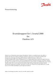
6. Type http://invertername in the address field:<br />
• Find the serial number on the product label, located on the side of the housing.<br />
• '<strong>Inverter</strong>name' is the final 10 digits of the serial number (1).<br />
Illustration 2.1: Product Label<br />
7. At initial startup of the inverter, the inverter runs a setup wizard.<br />
2.1.2. Setup Wizard<br />
Step 1 of 7: Master setting<br />
To set up a master inverter, click on [Set this inverter as master].<br />
• A scan runs to identify inverters in the network.<br />
8 L00410583-01_02
• A pop-up window shows the inverters successfully identified.<br />
Click [OK] to confirm that the correct number of inverters has been found.<br />
Illustration 2.2: Step 1 of 7: Master Setting<br />
To change this setting later, refer to Setup, <strong>Inverter</strong> Details.<br />
Step 2 of 7: Display language<br />
Select display language. Note that this selection defines the language in the display, not the<br />
grid code.<br />
• The default language is Chinese.<br />
Illustration 2.3: Step 2 of 7: Display Language<br />
To change the language setting later, refer to Setup, Setup Details.<br />
Step 3 of 7: Time and date<br />
Enter<br />
• time in 24-hour format<br />
• date<br />
• time zone<br />
2. Getting Started<br />
Accuracy is important, because date and time are used for logging purposes. Adjustment for<br />
daylight savings is automatic.<br />
L00410583-01_02 9<br />
2
2<br />
2. Getting Started<br />
Illustration 2.4: Step 3 of 7: Time and Date<br />
To change these settings later, refer to Setup, <strong>Inverter</strong> details, Set Date and Time.<br />
Step 4 of 7: Installed power<br />
For each PV input, enter<br />
• surface area<br />
• installed power<br />
Incorrect setting can have serious consequences for production efficiency.<br />
Illustration 2.5: Step 4 of 7: Installed Power<br />
To change the installed power, refer to Setup, Calibration, PV Array.<br />
10 L00410583-01_02
Step 5 of 7: Grid code<br />
Select the grid code to match the location of the installation. To meet medium-voltage grid requirements<br />
select a grid code ending in MV.<br />
• The default setting is [undefined].<br />
Select the grid code again, to confirm.<br />
• The setting is activated immediately.<br />
Correct selection is essential to comply with local and national standards.<br />
Illustration 2.6: Step 5 of 7: Grid Code<br />
Note:<br />
If the initial and confirmation settings are different,<br />
• grid code selection is cancelled<br />
• the wizard recommences step 5<br />
If initial and confirmation settings match, but are incorrect, contact service.<br />
Step 6 of 7: Replication<br />
To replicate the settings from steps 1 to 6 to other inverters in the same network<br />
• Select inverters<br />
• Click [Replicate]<br />
2. Getting Started<br />
Note:<br />
When the PV configuration, installed PV power and PV array area of follower inverters in the<br />
network differ from that of the master, do not replicate. Set up the follower inverters individually.<br />
L00410583-01_02 11<br />
2
2<br />
2. Getting Started<br />
Illustration 2.7: Step 6 of 7: Replication<br />
Step 7 of 7: <strong>Inverter</strong> startup<br />
The inverter will start automatically when the installation sequence is complete (see the<br />
TripleLynx CN Installation Manual), and solar radiation is sufficient.<br />
The startup sequence, including self-test, takes a few minutes.<br />
Illustration 2.8: Step 7 of 7: <strong>Inverter</strong> startup<br />
To change the setup later, access the inverter via the integrated web interface or the display, at<br />
inverter level.<br />
• To change the name of the inverter, go to [Setup → <strong>Inverter</strong> details]<br />
• To enable master mode, go to [Setup → <strong>Inverter</strong> details]<br />
12 L00410583-01_02
2.2. Operation<br />
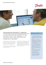
2.2.1. Web Server Structure<br />
The Web Server overview is structured as follows.<br />
Illustration 2.9: Overview<br />
1. <strong>Plant</strong> name: Displays the current plant name:<br />
• Click on the plant name to display the plant view.<br />
• Change the plant name at [Setup → <strong>Plant</strong> details].<br />
2. Group menu: Displays groups of inverters:<br />
• <strong>Inverter</strong>s join group 1 by default<br />
• Click on a group name to display the group view, and a list of inverters in the<br />
group.<br />
• Change the group name via [Setup → <strong>Inverter</strong> details] in the inverter view.<br />
3. Group members: Displays the inverter names in the group currently selected. The<br />
default inverter name is based on the serial number (see section Accessing the Web<br />
Server):<br />
• Click on an inverter name to display the inverter view.<br />
• Change the name of the inverter via [Setup → <strong>Inverter</strong> details] in the inverter<br />
view.<br />
4. Main menu: This menu corresponds to the inverter display main menu.<br />
2. Getting Started<br />
5. Sub menu: The sub menu corresponds to the main menu item currently selected. All<br />
sub menu items belonging to a particular main menu item are displayed here.<br />
6. Content area: The Web Server main menu and sub menus are identical to the menus<br />
in the inverter display. The sub menu content displayed here corresponds to the sub<br />
L00410583-01_02 13<br />
2
2<br />
2. Getting Started<br />
menu selected: [Overview]. On some pages, a horizontal menu is provided for improved<br />
readability.<br />
7. Footer: Options on the footer bar:<br />
• Language: Opens a pop-up window. Click on the country flag to change the<br />
language of the Web Server to the desired language for the active session.<br />
• Contact: Opens a pop-up window which displays <strong>Danfoss</strong> contact information.<br />
• Logout: Opens the log in / log out dialog box.<br />
• Security level: Displays the current security level as explained in the section<br />
Security Levels.<br />
Note:<br />
The content of the main menu changes depending on which view is currently selected: the<br />
plant, a group of inverters or an individual inverter. The active view is indicated by text in<br />
red.<br />
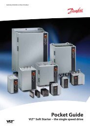
2.2.2. <strong>Plant</strong>, Group and <strong>Inverter</strong> Views<br />
The overview screens for plant view, group view, and inverter view display the same overall<br />
status information.<br />
Illustration 2.10: <strong>Plant</strong> View<br />
14 L00410583-01_02
Item Unit View Description<br />
<strong>Plant</strong><br />
and<br />
Group<br />
<strong>Inverter</strong><br />
Overall plant sta- - x Red: <strong>Plant</strong> PR < 50 %, or:<br />
tus<br />
Any inverter in the network<br />
- in fail safe mode, or<br />
- missing from the scan list, no contact with the master<br />
Yellow: Any inverter in the network<br />
- with PR < 70 %, or<br />
- in Connecting or Off grid mode<br />
Green: <strong>Plant</strong> PR ≥ 70 %, and<br />
- all inverters with PR ≥ 70 %, and<br />
- all inverters in On grid mode<br />
x Red: <strong>Inverter</strong> PR < 50 %, or inverter has an error<br />
Yellow: <strong>Inverter</strong> PR between 51 % and 70 %, or inverter<br />
in Connecting mode<br />
Green: No errors, and<br />
- inverter PR ≥ 70 %, and<br />
- inverter in On grid mode<br />
Current production kW x x Real time energy production level<br />
Yield today kWh x x Cumulative yield for the day<br />
Total revenue Euro x x Cumulative revenue earned since initial startup<br />
Total CO2 saving kg x x Cumulative CO2 saved since initial startup<br />
Performance ratio % x x Real time performance ratio<br />
Total yield kWh x x Cumulative yield since initial startup<br />
Power limit adjust- % x Maximum power limit as % of nominal inverter AC output<br />
ment<br />
rating<br />
Note:<br />
To calculate performance ratio PR, an irradiation sensor is required, see [Setup → Calibration].<br />
2.3. Security Levels<br />
Three predefined security levels filter user access to menus and options.<br />
Security levels:<br />
• Level 0: End-user, no password is needed<br />
• Level 1: Installer / service technician<br />
• Level 2: Installer / service technician (extended).<br />
When logged on to the Web Server as Admin, access is at security level 0. Subsequent user accounts<br />
created provide access to a predefined subset of menus, according to user profile.<br />
Define user profile at [<strong>Plant</strong> → Setup → Web Server → Profiles]<br />
Access to levels 1 and 2 requires a service logon, comprising a user ID and a password.<br />
• The service logon provides direct access to a specific security level for the duration of<br />
the current day.<br />
• Obtain the service logon from <strong>Danfoss</strong>.<br />
• Enter the logon via the Web Server logon dialog.<br />
• When the service task is complete, log off at [Setup → Security].<br />
• The Web Server automatically logs off the user after 10 minutes of inactivity.<br />
Security levels are similar on the inverter display and the Web Server.<br />
2. Getting Started<br />
L00410583-01_02 15<br />
2
2<br />
2. Getting Started<br />
A security level grants access to all menu items at the same level as well as all menu items of a<br />
lower security level.<br />
Throughout the manual, a [0], [1] or [2] inserted after the menu item indicates the minimum<br />
security level required for access.<br />
2.4. Compatibility in Networks with Other TripleLynx<br />
CN Pro <strong>Inverter</strong>s<br />
The specific functionality related to the TripleLynx CN Pro inverter only works in networks consisting<br />
of TripleLynx CN Pro inverters. Likewise, the specific functionality related to the<br />
TripleLynx CN Pro+ inverter only works in networks of TripleLynx CN inverters.<br />
2.5. Managing the Logged Data via the Integrated<br />
Web Server<br />
2.5.1. Graphs<br />
The TripleLynx CN Pro inverter has the ability to generate graphs either based on the entire<br />
plant, a particular group of inverters, or based on each individual inverter.<br />
The following types of graphs are available:<br />
• Production graphs on daily, monthly and annual basis.<br />
• Performance graphs on monthly and annual basis.<br />
For an in-depth description of each graph type, refer to the View section of this manual.<br />
Illustration 2.11: Production Graph<br />
2.5.2. Export of Logged Data<br />
Illustration 2.12: Performance Graph<br />
Data logged by the TripleLynx CN Pro inverter can be exported or downloaded to a PC.<br />
For further information, refer to Log.<br />
2.5.3. Yield Notification and Events<br />
Using the master inverter functionality, the TLX CN Pro+ inverter can send notifications by email<br />
or sms of:<br />
• production status<br />
• warning in the event of inadequate production level<br />
• inverter events<br />
16 L00410583-01_02
Requirements for notification by e-mail or sms:<br />
• All inverters are TLX CN Pro+ inverters.<br />
• The master is connected to the internet or has a GSM modem installed.<br />
• All settings regarding e-mail [Setup → Communication] and GSM [Setup → Communication<br />
→ GPRS setup] respectively are configured correctly.<br />
Requirements for sms only:<br />
• a GSM modem is installed in the master inverter, or<br />
• an e-mail to sms account from the ISP (internet service provider) is established.<br />
For further information on notifications, refer to Setup, Messaging.<br />
2.5.4. Upload to Web Portal or FTP Server<br />
The master inverter collects the data from all TripleLynx CN Pro inverters in its network. The<br />
data can be uploaded to a web portal or an FTP server when the master inverter:<br />
• is connected to a network with internet access, or<br />
• has a GSM modem installed<br />
For data upload frequency, refer to Setup, Communication, Data Warehouse (DW).<br />
2. Getting Started<br />
L00410583-01_02 17<br />
2
3<br />
3. View<br />
3. View<br />
3.1. Overview<br />
[0] [<strong>Plant</strong>, Group, <strong>Inverter</strong>]<br />
The layout of the overview screen on both plant, group and inverter basis is described in Chapter<br />
2, section Operation.<br />
3.2. Graphs [0] [<strong>Plant</strong>, Group, <strong>Inverter</strong>]<br />
The TLX CN Pro+ inverter can generate the following graphs on plant, group or inverter basis:<br />
Production graphs<br />
• Daily<br />
• Monthly<br />
• Yearly<br />
Performance graphs (PR or yield)<br />
• Monthly<br />
• Yearly<br />
The performance graphs display PR only when irradiation is logged.<br />
Note:<br />
The duration of data displayed in the graphs depends on the logging interval, see Logging.<br />
For a detailed description of each graph shown on each individual level, see below.<br />
3.2.1. <strong>Plant</strong> View<br />
Click on the plant name to display the plant view. In plant view the following graphs are generated<br />
based on data from the entire plant:<br />
Production graph<br />
Interval Unit Description<br />
Daily kW<br />
W/m2 Power output.<br />
Irradiation levels (when irradiation sensor is installed).<br />
Data are displayed on an hourly basis.<br />
Monthly kWh Energy production on a daily basis for the current month to date.<br />
Yearly kWh Energy production on a monthly basis for the current year to date.<br />
Performance graph (with irradiation sensor installed)<br />
Interval Unit Description<br />
Monthly % Performance ratio for the current month to date.<br />
Yearly % Performance ratio for the current year to date.<br />
Performance graph - yield (with no irradiation sensor installed)<br />
Interval Unit Description<br />
Monthly hours Operating time for month to date.<br />
Yearly hours Operating time for the year to date.<br />
18 L00410583-01_02
3.2.2. Group View<br />
Click on the group name to display the group view. In group view, a list of all inverters in the<br />
current group is displayed, detailing:<br />
• overall status (see Operation)<br />
• real time production level<br />
• total power output<br />
In group view, the following graphs are generated based on data from the current group:<br />
Production graph<br />
Interval Unit Description<br />
Daily kWh Energy production for the current day.<br />
Monthly kWh Energy production on a daily basis for the current month to date.<br />
Yearly kWh Energy production on a monthly basis for the current year to date.<br />
Performance graph - PR (with irradiation sensor installed)<br />
Interval Unit Description<br />
Monthly % Performance ratio in [%] for the current month to date.<br />
Yearly % Performance ratio in [%] for the current year to date.<br />
Performance graph - yield (with no irradiation sensor installed)<br />
Interval Unit Description<br />
Monthly hours Operating time for month to date.<br />
Yearly hours Operating time for the year to date.<br />
3.2.3. <strong>Inverter</strong> View<br />
Click on the inverter name to display the inverter view. In inverter view, the following graphs<br />
are generated based on inverter data:<br />
Production graph<br />
Interval Unit Description<br />
Daily W<br />
Active power<br />
VA<br />
Apparent power<br />
VAr<br />
Reactive power<br />
W<br />
PV power<br />
Monthly kWh Energy production on a daily basis, month to date.<br />
Yearly kWh Energy production on a monthly basis, year to date.<br />
Performance graph - PR (with irradiation sensor installed)<br />
Interval Unit Description<br />
Monthly % Performance ratio in [%] for the current month to date.<br />
Yearly % Performance ratio in [%] for the current year to date.<br />
Performance graph - yield (with no irradiation sensor installed)<br />
Interval Unit Description<br />
Monthly hours Operating time for month to date<br />
Yearly hours Operating time for the year to date.<br />
3. View<br />
L00410583-01_02 19<br />
3
4<br />
4. Status<br />
4. Status<br />
4.1. Status<br />
All values displayed in the Status are read-only. To change the inverter settings, see the Setup<br />
section. For a detailed description of the individual settings, refer to the TripleLynx CN Reference<br />
Manual.<br />
As the values are requested live from the inverter, short delays may occur in retrieving data.<br />
Fetch the newest inverter data by pressing the 'Reload' button.<br />
4.2. Ambient Conditions [0] [<strong>Inverter</strong>]<br />
If external sensors are connected to the inverter, their current values are displayed here.<br />
Illustration 4.1: Ambient Conditions<br />
4.3. Photovoltaic [0] [<strong>Inverter</strong>]<br />
In the photovoltaic status, menu all status information and settings related to the PV side of the<br />
inverter are displayed.<br />
4.3.1. PV Present Values<br />
[0] [<strong>Inverter</strong>]<br />
The voltage, current and power detected on each PV input are displayed here.<br />
4.3.2. PV Maximum Values [0] [<strong>Inverter</strong>]<br />
The maximum values of voltage, current and power recorded on each PV input are displayed<br />
here.<br />
The maximum values can be reset via [<strong>Inverter</strong> view → Setup → <strong>Inverter</strong> details → Reset max.<br />
values].<br />
4.3.3. PV Input Energy [0] [<strong>Inverter</strong>]<br />
The total daily energy produced by all three PV inputs as a sum and by each PV input individually<br />
are shown.<br />
Note:<br />
If two inputs are running in parallel configuration, only one value will be shown.<br />
20 L00410583-01_02
4.3.4. Isolation Resistance [0] [<strong>Inverter</strong>]<br />
The isolation resistance between the earth and PV arrays is displayed in Ohm (Ω). The isolation<br />
resistance is measured during the inverter self-test at startup.<br />
4.3.5. PV Configuration [1] [<strong>Inverter</strong>]<br />
The current configuration of each PV input is shown.<br />
4.4. AC Grid [0] [<strong>Inverter</strong>]<br />
This menu section displays the status of values related to the AC side of the inverter.<br />
4.4.1. Present Values [0] [<strong>Inverter</strong>]<br />
For each of the three phases, the real time AC grid values are displayed for the current phase:<br />
Item Description<br />
Voltage [0] Voltage<br />
10 min. mean [1] The average voltage sampled over 10 min.<br />
L1-L2 [1] Phase to phase voltage<br />
Current [0] Current<br />
DC content of current [1] The DC content of the AC grid current<br />
Frequency [0] Frequency<br />
Power [0] The power on the current phase<br />
Apparent power (S) [1] Apparent power on the phase in question<br />
Reactive power (Q) [1] The reactive power on the phase in question<br />
4.4.2. Maximum Values [0] [<strong>Inverter</strong>]<br />
The maximum voltage, current and power values registered on the AC grid phase 1, 2 and 3,<br />
are displayed here.<br />
Reset the maximum values at [<strong>Inverter</strong> view → Setup → <strong>Inverter</strong> details → Reset max. values].<br />
4.4.3. Residual Current Monitor<br />
[0] [<strong>Inverter</strong>]<br />
The current and max. current value seen by the Residual Current Monitor Unit (RCMU).<br />
Item Description<br />
Current [0] Displays the rms value of residual current.<br />
Maximum value [1] Displays the maximum recorded rms value of residual current.<br />
4.5. Grid Management [0] [<strong>Inverter</strong>]<br />
Grid management displays the current status of power level adjustment current production and<br />
settings for frequency stabilization.<br />
The grid management menu is only displayed if the functionality is enabled in the current grid<br />
code.<br />
4. Status<br />
L00410583-01_02 21<br />
4
4<br />
4. Status<br />
4.6. Reactive Power [1] [<strong>Plant</strong>]<br />
The setpoint type and setpoint value of reactive power are displayed here, for TLX CN Pro+<br />
variants only.<br />
Item Description<br />
Setpoint type Displays the setpoint type<br />
Value Displays the value of the setpoint<br />
4.7. <strong>Inverter</strong> [0] [<strong>Inverter</strong>]<br />
The status inverter content page displays the general status of the complete inverter.<br />
4.7.1. General [0] [<strong>Inverter</strong>]<br />
Note:<br />
When calling Service, note that the information listed on this web page is required in order<br />
to obtain assistance.<br />
The general settings of the inverter are displayed here.<br />
Item Description<br />
Country Installation country.<br />
Language Language of inverter display and Web Server software. The session language<br />
of the Web Server software can also be changed via the footer.<br />
Name *) Displays the current name of the inverter.<br />
Group name *) Displays the name of the group to which the inverter belongs. *)<br />
Operation mode Displays the current mode of operation of the inverter.<br />
Installation date The date on which the inverter was installed. *)<br />
Model Current model and inverter power class.<br />
Serial number The serial number of the inverter.<br />
Product number The product number of the inverter.<br />
Software version The software version of the inverter.<br />
MAC address The MAC address of the communication board.<br />
*) These names can be changed in inverter view at [<strong>Inverter</strong> view → Setup → <strong>Inverter</strong> details].<br />
4.7.2. DC bus voltage [1] [<strong>Inverter</strong>]<br />
The current and maximum values of the DC bus voltage are shown here. The DC bus voltages<br />
have both a lower and an upper limit.<br />
4.7.3. PCB Temperatures [0] [<strong>Inverter</strong>]<br />
Internal temperatures of the inverter PCB’s:<br />
• current temperature<br />
• maximum temperature [1]<br />
Note:<br />
Some PCB temperatures are only accessible at security level 1 or above.<br />
22 L00410583-01_02
4.7.4. RPM of Fans [1] [<strong>Inverter</strong>]<br />
The internal fan speed is displayed in RPM.<br />
4.7.5. Power Module Temperatures [0] [<strong>Inverter</strong>]<br />
Internal temperature of the inverter power modules:<br />
- current temperature<br />
- maximum temperature [1]<br />
Note:<br />
Some power module temperatures are only accessible at security level 1 or above.<br />
4.7.6. PCB Part and Serial Number [0] [<strong>Inverter</strong>]<br />
The part and serial number of the control board as well as the power board, the communication<br />
board, and the aux board are displayed here.<br />
4.7.7. PCB Software version [0] [<strong>Inverter</strong>]<br />
The software version of the control board, communication board, the functional safety processor<br />
and the display software are shown here.<br />
4.7.8. Operating Time [1] [<strong>Inverter</strong>]<br />
Total operating time of the power, aux, control and communication boards.<br />
4.8. Software Version [0] [<strong>Plant</strong>]<br />
Software version of the TripleLynx CN Pro Web Server.<br />
4.9. Upload Status [0] [<strong>Plant</strong>]<br />
The modem menu displays the current status of the GSM/GPRS connection and the status of<br />
the data warehouse/portal upload.<br />
Item Description<br />
Upload status Current upload status.<br />
Signal strength Signal strength. Should preferably be between 16-31. GSM signal<br />
strength.<br />
GSM network name The network to which the modem is currently connected.<br />
GSM status Displays the current GSM network status.<br />
Failed uploads Number of consecutive failed uploads.<br />
Last error Event ID together with timestamp (time and date) of the last event. Refer<br />
to the GSM Manual for a further description of the event ID’s.<br />
Last upload Timestamp of last successful upload.<br />
Table 4.1: Upload Status<br />
For further information, refer to the GSM Manual.<br />
4. Status<br />
L00410583-01_02 23<br />
4
5<br />
5. Log<br />
5. Log<br />
5.1. Logging<br />
This section explains the individual logs of the TripleLynx CN Pro. All individual logs can be<br />
downloaded as .csv file for further processing. Not all logs are visible in both plant and inverter<br />
views.<br />
When the internal log of the inverter is full, it will overwrite the oldest data first. To set up a<br />
notification when the internal logging capacity of the inverter is 60 % full, refer to the section<br />
Messaging.<br />
Note:<br />
In Internet Explorer ® , Firefox ® and/or firewall software, the file download/export of the logged<br />
data might be prevented by pop-up blockers. Refer to the program supplier for further<br />
information and options.<br />
5.2. General [0] [<strong>Plant</strong>, <strong>Inverter</strong>]<br />
Displayed in inverter view:<br />
• Total energy production<br />
• Total operating time<br />
• Time of power down (previous day)<br />
• Time of power up (current day)<br />
Displayed in plant view:<br />
• Total energy production for entire plant<br />
Note:<br />
Time of power down and power up are displayed only when the inverter has been operating.<br />
5.3. Derating [1] [<strong>Inverter</strong>]<br />
Derating the output power is a means of protecting the inverter against overload and potential<br />
failure. The log records total duration of derating. To view the distribution of the various types<br />
of derating, level 1 security access is needed. For more information on derating, refer to the<br />
TripleLynx CN Reference Manual.<br />
This menu is visible at inverter and group levels.<br />
24 L00410583-01_02
Value Unit Description<br />
Off-grid counter [0] Hour Total duration of disconnection from grid.<br />
Total derate coun- Hour Total duration of power production limitation.<br />
ter [0]<br />
Grid voltage [1] Hour Total duration of derating due to the grid voltage.<br />
Grid current [1] Hour Total duration of derating due to the grid current.<br />
Grid power [1] Hour Total duration of derating due to the grid power.<br />
PV current [1] Hour Total duration of derating due to the PV current.<br />
PV power [1] Hour Total duration of derating due to PV power.<br />
Temperature [1] Hour Total duration of derating due to the inverter temperature.<br />
Power Level Adjustment<br />
[0] 1)<br />
Hour Total duration of derating due to Power Level Adjustment.<br />
Frequency stabiliza- Hour Total duration of derating due to frequency stabilization.<br />
tion [0]<br />
Reactive power [0] Hour Total duration of derating due to reactive power.<br />
1) If enabled by the current grid code.<br />
5.4. Data Log [0] [<strong>Inverter</strong>]<br />
The TLX CN Pro+ inverter logs detailed data for a total of 34 days at 10-minute logging intervals<br />
before it starts to overwrite the data.<br />
Logged data:<br />
Data Unit<br />
Timestamp dd:mm:yy hh:mm<br />
Irradiance1) W/m2 Ambient temperature1) °C<br />
Module temperature1) °C<br />
PV voltage, per string V<br />
PV current, per string A<br />
PV power, per string W<br />
PV energy, per string Wh<br />
Grid voltage, per phase V<br />
Grid current, per phase A<br />
Grid power, per phase W<br />
Apparent power, sum of phases VA<br />
Grid power total W<br />
Grid energy, per phase Wh<br />
Today's energy production measured by S0 coun- Wh<br />
ter 2)<br />
DC content of grid current, per phase mA<br />
Residual grid current mA<br />
Grid frequency, mean of phases Hz<br />
DC bus voltages V<br />
Internal temperatures °C<br />
Apparent power, per phase VA<br />
Reactive power, per phase Var<br />
<strong>Inverter</strong> operation mode<br />
Latest inverter event<br />
PLA present value %<br />
Reactive power abs(Q) %<br />
Reactive power cos(φ)<br />
Reactive power mode<br />
1) When sensor connected.<br />
2) When counter connected.<br />
5.5. Production Log [0] [<strong>Plant</strong>, <strong>Inverter</strong>]<br />
These data are logged at inverter level:<br />
5. Log<br />
L00410583-01_02 25<br />
5
5<br />
5. Log<br />
• Daily energy production data during the past week.<br />
• The weekly energy production data for the past 4 weeks.<br />
• The monthly energy production for the past 12 months.<br />
• The yearly energy production for the past 20 years.<br />
If inverter exchange is required, data can be transferred to the new inverter. Refer to the section<br />
Settings Backup for further information. At plant level, this log displays the sum of energy<br />
production for all inverters in the network.<br />
5.6. Irradiation Log [0] [<strong>Plant</strong>, <strong>Inverter</strong>]<br />
When the inverter is equipped with an irradiation sensor, these data are logged at inverter level:<br />
• Daily irradiation of the past week<br />
• Weekly irradiation for the past 4 weeks<br />
• Monthly irradiation for the past 12 months<br />
• Annual irradiation for the past 20 years<br />
If inverter exchange is required, data can be transferred to the new inverter. Refer to the section<br />
Settings Backup for further information.<br />
In plant view, this menu displays the irradiation log of the master inverter.<br />
5.7. Event Log [0] [<strong>Inverter</strong>]<br />
The event log menu displays the 20 most recent inverter events.<br />
Latest 20 events [1] displays<br />
• event ID<br />
• date and time<br />
• status (on/off)<br />
for each of the most recent 20 events.<br />
See the section Troubleshooting in the TripleLynx CN Reference Manual for more information<br />
on specific events.<br />
The complete event log consists of max. 1000 entries, which can be viewed by exporting the<br />
event log. This menu is visible in inverter view only.<br />
5.8. Change Log [1] [<strong>Inverter</strong>]<br />
Displays the most recent 20 entries from the change log of the inverter.<br />
The change log records:<br />
• Changes to functional safety parameters.<br />
• Each logon with service password.<br />
View the content of the change log by exporting the log.<br />
26 L00410583-01_02
Note:<br />
The change log keeps track of all modifications made to parameters accessed at security level<br />
2. The log includes:<br />
• Parameter changed<br />
• New setting<br />
• Timestamp<br />
• User name of user making the change. View the change log at [<strong>Inverter</strong> view → Log<br />
→ Change Log].<br />
5.9. Grid Management Log [0] [<strong>Plant</strong>, <strong>Inverter</strong>]<br />
Contains a power reduction telegram received from the master inverter.<br />
The Web Server only displays the latest 20 entries. The complete log can be viewed by exporting<br />
the log.<br />
5.10. Reactive Power [0] [<strong>Inverter</strong>]<br />
This menu item is available for:<br />
• TripleLynx CN Pro+ variants only<br />
• Grid codes where reactive power is enabled<br />
Displays a log of the sum of generated reactive energy:<br />
• Under-excited<br />
• Over-excited<br />
5. Log<br />
L00410583-01_02 27<br />
5
6<br />
6. Setup<br />
6. Setup<br />
6.1. Calibration [0] [<strong>Plant</strong>, <strong>Inverter</strong>]<br />
Configuration of individual sensors, PV arrays and environmental settings.<br />
6.1.1. Sensors [0] [<strong>Plant</strong>, <strong>Inverter</strong>]<br />
Illustration 6.1: Sensors<br />
Item Unit Description<br />
Irradiation sensor scale mV(1000 w/m2 ) The calibration value of the irradiation sensor.<br />
The value is usually written on a label at the back of the<br />
sensor.<br />
Note that this value must be entered before the inverter<br />
will recognise that there is an irradiation sensor connected.<br />
Irradiation sensor temp. coeff.<br />
% Calibration value for internal temperature correction of<br />
the irradiation measurement. Only used for irradiation<br />
sensors with integrated temperature compensation.<br />
PV temp. offset °C The temperature sensor may be calibrated using an offset<br />
ranging from −5.0 to 5.0 °C.<br />
Ambient temp. offset °C The temperature sensor may be calibrated using an offset<br />
ranging from −5.0 to 5.0 °C.<br />
S0 scale pulses/kWh In order to use an energy meter (S0 sensor), the scale<br />
of the energy meter must be entered here.<br />
For a description of which sensor to connect to the TripleLynx CN Pro, refer to the TripleLynx<br />
CN Installation Manual.<br />
6.1.2. PV Array [0] [<strong>Inverter</strong>]<br />
The PV area and the rated PV power (STC) for the installation are defined here.<br />
Note:<br />
These definitions are required to calculate PV string comparison for the plant status report.<br />
Refer to Messaging.<br />
28 L00410583-01_02
Illustration 6.2: PV Array<br />
Item Unit Description<br />
PV1 array area m 2 Input 1 - total PV array area<br />
PV1 array power W Input 1 - total rated output of PV panels<br />
PV2 array area m 2 Input 2 - total PV array area<br />
PV2 array power W Input 2 - total rated output of PV panels<br />
PV3 array area m 2 Input 3 - total PV array area<br />
PV3 array power W Input 3 - total rated output of PV panels<br />
6.1.3. Environment [0] [<strong>Plant</strong>, <strong>Inverter</strong>]<br />
Via the environment menu in plant view, the values for total reimbursement and total CO2 emission<br />
can be configured.<br />
Illustration 6.3: Calculation Values<br />
Item Unit Description<br />
Start value for yield count kWh Defines the value (an offset) from where the yield<br />
count used in the calculation of reimbursement and<br />
CO2 emission begins.<br />
Reimbursement ct/kWh Euro cent per KWh Defines a value for the financial yield.<br />
Note: Defining this value requires considerable knowledge<br />
of the individual reimbursement models of the<br />
different countries. The default value is 0.00.<br />
CO2 emissions factor CO2/kg Allows the conversion of yield/kWh. This calculation<br />
factor for CO2 saving depends on the energy source to<br />
power generation ratio. Per default it is set to 0.5 C02/<br />
kg. Ask the local electricity provider for an exact value.<br />
6. Setup<br />
L00410583-01_02 29<br />
6
6<br />
6. Setup<br />
6.2. Communication [0][<strong>Plant</strong>, <strong>Inverter</strong>]<br />
The communication menu contains the following sub menus; see descriptions below. Some of<br />
the menus are only visible in plant view whereas others are only visible in inverter view.<br />
6.2.1. RS485 [0] [<strong>Inverter</strong>]<br />
Illustration 6.4: RS485 Network Address<br />
Change the RS485 network address of the inverter here. Ensure that each inverter in the network<br />
has a unique address.<br />
The RS485 addresses must be selected within the following range (network.subnet.address):<br />
2.1.1 to 12.14.254.<br />
Note:<br />
Only in very rare cases will it be necessary to change the RS485 address of the inverter as<br />
each inverter is delivered with a unique RS485 address.<br />
6.2.2. IP Setup [0] [<strong>Inverter</strong>]<br />
The TripleLynx CN Pro inverter is equipped with two integrated Ethernet interfaces, which connectivity<br />
to Ethernet networks.<br />
The inverter automatically configures a unique IP address.<br />
An integrated DNS server enables access to the master inverter via its name or serial number.<br />
For local administration of IP addresses, the inverter also supports DHCP in the automatic configuration.<br />
Alternatively, IP addresses can be administrated manually under [Setup → Communication → IP<br />
setup].<br />
View the inverter IP address via the display at [Setup → Communication setup → IP setup].<br />
Note:<br />
For manual configuration, ensure that each inverter has a unique IP address.<br />
30 L00410583-01_02
Item Description<br />
Configuration Options:<br />
• Manual<br />
• Automatic<br />
The following settings are obtained automatically if automatic configuration is selected, otherwise they<br />
have to be entered manually. They are only visible when [Configuration → Manual] is chosen.<br />
IP address IP address<br />
Subnet mask Subnet mask<br />
Standard gateway IP address of the Internet gateway. This address can be requested from the<br />
network administrator.<br />
DNS server This parameter can be requested from the network administrator.<br />
6.2.3. Communication Channel [0] [<strong>Plant</strong>]<br />
This menu item is available for TLX CN Pro and TLX CN Pro+ only.<br />
Selection of a communication channel is the first step in configuration of email transmission and<br />
FTP upload.<br />
Illustration 6.5: Communication Channel<br />
Item Description<br />
Communication channel Select the desired communication channel for FTP upload and email<br />
transmission.<br />
Select ‘GSM’ or ‘Local network’<br />
Default is ‘Not present’<br />
Procedure:<br />
• Select ‘GSM’ to transmit FTP upload and emails via the optional GSM modem.<br />
• Select ‘Local network’ to transmit FTP upload and emails via Ethernet.<br />
Email and FTP upload configuration<br />
Selection of a communication channel is required to define a route for email transmission and/<br />
or FTP upload.<br />
To fully activate email communication or FTP upload, additional configuration is required. For<br />
further information, refer to the sections GPRS Setup, SMTP Setup and Data Warehouse/ FTP<br />
Upload.<br />
Note that when the communication channel is set to 'Not present', no FTP upload or email<br />
transmission will take place, even when GPRS, SMTP and/or Data Warehouse are configured.<br />
SMS configuration<br />
For SMS communication, no ‘communication channel’ setting is required. For configuration of<br />
SMS communication, refer to the section Recipient.<br />
6.2.4. GPRS Setup [0] [<strong>Plant</strong>]<br />
Configure the GPRS settings of the inverter here. They are required so the GSM modem can<br />
connect to the internet to send e-mails or upload data to a web portal or FTP server.<br />
6. Setup<br />
L00410583-01_02 31<br />
6
6<br />
6. Setup<br />
This menu is visible when the master inverter is equipped with a GSM modem and a valid SIM<br />
card.<br />
Illustration 6.6: GPRS Setup for GSM networking<br />
Note:<br />
In order for messaging or DW upload (FTP server upload) via GSM to work it is essential that<br />
the GPRS setup has been configured correctly.<br />
Item Description<br />
SIM pin Here the SIM PIN code is entered, if applicable.<br />
code The PIN code can consist of 4-8 characters.<br />
Access Connection information from the GPRS service provider.<br />
point name This information together with a user name and password can be requested by the SIM card<br />
supplier and is needed in order for the inverter to be able to dial in to the internet. Max. 24<br />
characters.<br />
User name User name assigned by the GPRS service provider.<br />
Max. 24 characters.<br />
Password Password assigned by the GPRS service provider. For security reasons, every password character<br />
is displayed as an asterisk (*).<br />
Password<br />
again<br />
Retype the password<br />
Network • Checked (Enabled)<br />
roaming<br />
• Not checked (Disabled)<br />
6.2.5. SMTP Setup [0] [<strong>Plant</strong>]<br />
Per default the network roaming check box is not checked.<br />
If checked, the GPRS modem is allowed to connect to the internet via a network which is not<br />
the home network (a network which does not belong to the network of the telephone company).<br />
Roaming is not a free service and the telephone company will most likely impose extra<br />
charges.<br />
In the SMTP setup menu, the mail-server settings for exchanging e-mails are specified. Parameters<br />
here include SMTP server, logon, password, sender address, and authentication type.<br />
32 L00410583-01_02
Note:<br />
A correctly configured SMTP server and internet connection, IP and DNS server, are necessary<br />
for receiving e-mail messages from the inverter. To test the SMTP settings go to [Setup →<br />
Messaging] on plant view, configure a recipient and press the 'Test Setup' button. Within a<br />
few minutes, a test e-mail will be sent from the inverter.<br />
Illustration 6.7: STMP Setup<br />
Item Description<br />
SMTP server address Outbox server; this information can be requested from the Internet<br />
provider (see below) or LAN administrator.<br />
SMTP server port Here the server port used for the e-mail transfer can be changed. At<br />
delivery it is configured to port 25.<br />
Ask the network administrator before changing this value.<br />
User name Service provider's user name. A maximum of 24 characters can be entered.<br />
Password Password assigned by the Internet service provider. For security reasons,<br />
every password character is displayed as an asterisk (*). A maximum<br />
of 24 characters can be entered.<br />
Retype password Retype the password.<br />
E-mail sender address Sender's e-mail address used for authenticating the SMTP server. An<br />
unknown sender address can cause e-mail delivery to fail.<br />
User Authentication As authentication type exclusively SMTP authentication is supported!<br />
If the authentication check box is checked, remember to enter the account<br />
information of the e-mail. This information will be forwarded by<br />
the internet provider.<br />
6. Setup<br />
L00410583-01_02 33<br />
6
6<br />
6. Setup<br />
6.2.6. Data Warehouse [0] [<strong>Plant</strong>] / FTP Server Upload<br />
Illustration 6.8: Data Warehouse<br />
Item Description<br />
Upload time [0] Time of day when the upload takes place, only used when upload interval is<br />
configured to 'daily'.<br />
Upload interval [0] Hourly<br />
Daily<br />
Weekly<br />
Monthly<br />
Disabled<br />
FTP server address [1] The FTP server address is user configurable. It can be a name or IP address.<br />
A maximum of 24 characters can be entered.<br />
FTP server port [1] FTP server port is user configurable.<br />
Default port is 21<br />
FTP mode [1] FTP connection mode is user configurable. The following options exists:<br />
- Passive<br />
- Active<br />
Default mode is “Active”<br />
FTP server user name [0] Both the user name and the password for the FTP session (web portal upload)<br />
established by the TLX CN Pro+ inverter can be configured by the user.<br />
If empty, the serial number of the inverter is used. A maximum of 24 characters<br />
can be entered.<br />
Password [0] The password for the FTP/web portal account. A maximum of 24 characters<br />
can be entered.<br />
Start log upload now [0] Tests the FTP upload immediately. To check status go to [<strong>Plant</strong> → Status →<br />
Upload status]<br />
Note:<br />
A prerequisite for a successful data transfer to the data warehouse is a valid and active portal<br />
account. Receive further details directly from the data warehouse/web portal provider.<br />
When registering the inverter at a data warehouse/web portal provider, they often need the serial<br />
number of the inverter which sends the data to the portal; in this case it is the serial number<br />
of the master inverter. The serial number of the inverter can be found via [Status → <strong>Inverter</strong>]<br />
or on the name plate on the side of the inverter. Use the last 10 digits.<br />
34 L00410583-01_02
6.2.7. Remote Access [2] [<strong>Inverter</strong>]<br />
As per default it is not possible to change the functional safety settings of the inverter via the<br />
Web Server. To be able to do so, enable the remote access check mark. Note that this must be<br />
done individually for each inverter in the system.<br />
Illustration 6.9: Change Functional Safety Settings<br />
The following functional safety parameters can be set here:<br />
• Rate of change of frequency, maximum amount, and time to trip<br />
• 10-minute mean value of grid voltage, maximum amount, and time to trip<br />
Modifications made to parameters at security level 2 are recorded. See the section Change Log.<br />
To change other functional safety settings, refer to the TripleLynx CN Reference Manual.<br />
6.3. External Alarm[0] [<strong>Inverter</strong>]<br />
6.3.1. External Alarm [0] [<strong>Inverter</strong>]<br />
Illustration 6.10: External Alarm<br />
To use this feature, connect an external notification device, e.g. a lamp to the relay output of<br />
the TripleLynx CN Pro inverter. For further instructions on how to connect the device, refer to<br />
the TripleLynx CN Installation Manual.<br />
If the alarm is triggered, it will remain active for the period of time defined under 'Alarm timeout'<br />
(the value 0 disables the time-out functionality and the alarm will sound continuously).<br />
While the alarm is active it can be stopped at any time by pressing the 'Stop' button. The relay<br />
output can be tested by pressing the 'Test' button.<br />
6. Setup<br />
L00410583-01_02 35<br />
6
6<br />
6. Setup<br />
The alarm is activated by the occurrence of a predefined inverter event. Refer to the TripleLynx<br />
CN Reference Manual for a complete list of which events can enable the external alarm output<br />
of the TripleLynx CN Pro inverter.<br />
Note:<br />
The external alarm functionality only works per individual inverter; it cannot be configured<br />
on plant basis.<br />
6.4. <strong>Inverter</strong> Details [0] [<strong>Inverter</strong>]<br />
6.4.1. General<br />
[0] [<strong>Inverter</strong>]<br />
The specific inverter settings for the TripleLynx CN Pro variant are defined here:<br />
• Selecting a master<br />
• Changing the name of the inverter or the group to which it belongs<br />
If the particular inverter is a master in its network, view the list of follower inverters by pressing<br />
the 'Show list' button.<br />
The inverter is delivered with default names for both inverter and group, see the table below.<br />
Illustration 6.11: <strong>Inverter</strong> Details<br />
36 L00410583-01_02
Item Description<br />
<strong>Inverter</strong> name The name of the inverter. At delivery, this name corresponds to the serial<br />
number of the inverter. A maximum of 15 characters can be entered, see the<br />
section Supported Characters for a complete list of the valid characters.<br />
<strong>Inverter</strong> group name In order to group the inverters of the plant into different groups, a group<br />
name is needed. A maximum of 15 characters can be used, see the section<br />
Supported Characters for a complete list of the valid characters.<br />
To add more inverters to the same group just enter the same group name for<br />
all inverters.<br />
<strong>Inverter</strong>s are delivered with the default group name Group 1.<br />
<strong>Inverter</strong> is master This check box needs to be enabled if this particular inverter is the master<br />
inverter in the network.<br />
Enabling the master check box and pressing 'Save' generates an automatic<br />
network scan and the 'Scan network' button will appear.<br />
Per default the master check box is unchecked.<br />
'Scan network' Press this button to scan for connected inverters.<br />
The names of the inverters found will appear in the list. Check manually that<br />
all connected inverters have been found. A network scan can be renewed at<br />
any time. Newly found inverters will be added to the list, and inverters not<br />
present in the network anymore will automatically be deleted from the list.<br />
NOTE! The 'Scan network' button is only visible if the inverter is set up as<br />
the master inverter.<br />
Show list Pressing the 'Show list' button will open a pop-up window, which displays the<br />
names of all the inverters currently connected to the master together with<br />
their current status. Via the pop-up window it is possible to perform a quick<br />
communication check from the master inverter to the other inverters. This is<br />
done by pressing the 'Check communication' button.<br />
NOTE! The 'Scan network' button is only visible if the inverter is set up as<br />
the master inverter.<br />
6.4.2. Date and Time [0] [<strong>Plant</strong>, <strong>Inverter</strong>]<br />
This menu is visible in plant and inverter views only.<br />
The date/time settings of the inverter can be changed here.<br />
Illustration 6.12: Date and Time<br />
Item Description<br />
Time The current time in the following format: hh:mm:ss<br />
Be careful when changing the time settings of the inverter as changing the<br />
time affects data which are already logged.<br />
Setting the time back one hour will result in the existing data logged for the<br />
last hour being overwritten.<br />
Date The current date in the following format: dd-mm-yyyy.<br />
Be careful when changing the date of the inverter as a date change affects<br />
data which are already logged.<br />
TimeZone Time zone in which the inverter is located.<br />
Note:<br />
The master inverter automatically ensures<br />
• identical date and time settings, and<br />
• adjustment to summer time throughout the network.<br />
6. Setup<br />
L00410583-01_02 37<br />
6
6<br />
6. Setup<br />
6.5. Logging [0] [<strong>Inverter</strong>]<br />
6.5.1. Logging Interval [0] [<strong>Inverter</strong>]<br />
Configure the logging interval of the individual inverter at [<strong>Inverter</strong> → Setup → Logging].<br />
Logging intervals:<br />
• 1 minute<br />
• 10 minutes<br />
• 1 hour<br />
Illustration 6.13: Logging Interval<br />
Note:<br />
Web portals support differing logging intervals. Ask the service provider.<br />
Note:<br />
Changes to the logging interval impact:<br />
• logging of detailed inverter data<br />
• inverter logging capacity<br />
For more information, refer to the section Logging Capacity.<br />
6.5.2. Logging Capacity [0][<strong>Inverter</strong>]<br />
This menu displays the current logging capacity of the data log of the particular inverter.<br />
[<strong>Inverter</strong> → Setup→ Logging]<br />
The logging capacity of the inverter depends on the current logging interval configuration. With<br />
a default logging interval of 10 min., the inverter can log its detailed inverter data for a maximum<br />
of 34 days. It will then start to overwrite the old data.<br />
6.5.3. Delete Logs [1] [<strong>Inverter</strong>]<br />
At security level 1, go to [<strong>Inverter</strong> → Setup → Logging] to delete the Event, production, irradiation<br />
and data log of each individual inverter.<br />
This menu is visible in inverter and group views.<br />
Note:<br />
Deleting a log is an unrecoverable action and data will be lost.<br />
6.6. Grid Management [1] [<strong>Plant</strong>]<br />
This menu applies to TLX CN Pro+ variants only.<br />
38 L00410583-01_02
[Setup → Grid management]<br />
Set up ancillary services such as Power Level Adjustment (PLA) and Reactive Power in this area.<br />
6.6.1. General [1] [<strong>Plant</strong>]<br />
Illustration 6.14: General<br />
Item Description<br />
Nominal plant AC power Enter the total nominal AC power for the entire plant. This value is necessary for<br />
correct calculation of the absolute reactive power Q.<br />
Q and PF settle time Enter the system settling time for reactive power regulation.<br />
Range: 10 – 60 seconds.<br />
Control type Specifies whether the control should be Open loop (enabled) or Off (disabled).<br />
Reference value Select a reference for reactive power<br />
• Grid management box<br />
Grid management box<br />
• Reactive power Q<br />
• Power factor PF<br />
• Set point curve PF(P)<br />
• Set point curve Q(U)<br />
• The grid management box receives set point values for reactive power and PLA from<br />
the DNO. Configure the grid management box inputs under: Relay configuration. For<br />
more information refer to the TripleLynx CN Reference Manual and the Grid Management<br />
Box Manual.<br />
Reactive power Q<br />
• Enter the fixed set point value for the plant reactive power Q as either:<br />
- percentage value of the nominal plant AC power (%)<br />
Range: 0 – 60% of the nominal plant AC power, over-excited or under-excited.<br />
- value of Q (kVAr)<br />
Power Factor PF<br />
Enter the fixed set point value for the plant power factor.<br />
Range: 1 – 0.8 over-excited or under-excited.<br />
Set point curve PF(P)<br />
The power factor is defined as a function of the plant output power. Enter the values for the set<br />
point curve under: PF(P) Curve.<br />
6. Setup<br />
L00410583-01_02 39<br />
6
6<br />
6. Setup<br />
Set point curve Q(U)<br />
Reactive power is defined as a function of the grid voltage, either as a percentage of the nominal<br />
plant power or directly in kVAr. Enter the values for the set point curve under: Q(U) Curve.<br />
6.6.2. Relay Configuration [1] [<strong>Plant</strong>]<br />
When grid management box is selected as reference value, configure the discrete inputs K1 –<br />
K4.<br />
Each of the 16 combinations of the four discrete inputs corresponds to a specific plant output<br />
power level (PLA) and a reactive power output:<br />
Illustration 6.15: Relay configuration<br />
Item Description<br />
K1-K4 active Enable (check) or disable (uncheck) the individual inputs, K1-K4. If the input is<br />
disabled, its state is ignored (considered off).<br />
Power level in % PLA setting. Output power reduction as percentage of the plant nominal AC<br />
power.<br />
Reactive power Reactive power (Q) output in % or kVAr.<br />
Power factor Output power factor (PF).<br />
6.6.3. Set Point Curves [1] [<strong>Plant</strong>]<br />
The TLX CN Pro+ inverter is capable of generating reactive power on basis of predefined set<br />
point curves, either:<br />
• Reactive power (Q) as a function of the grid voltage<br />
• Power Factor (PF) as a function of the plant output power<br />
The set point curves are defined by values and displayed as a graphical curve.<br />
40 L00410583-01_02
Over-excited energy is always displayed above the horizontal axis, and under-excited energy<br />
below the axis.<br />
The curve ends are always horizontal, meaning that the inverters will operate with the first set<br />
point (1) below that power or voltage level and with the last set point (9) above that power or<br />
voltage level.<br />
The reference for the grid voltage is measured on the grid side of the master inverter.<br />
The reference for the plant output power is calculated by the master inverter.<br />
Reactive power generation will follow the specified set point curves when sufficient PV power is<br />
available.<br />
To define the PF(P) set point curve:<br />
- enter up to nine pairs of values<br />
- select under-excited or over-excited for each<br />
Illustration 6.16: PF(P) Set Point Curves - Power Factor<br />
To define the Q(U) set point curve:<br />
- select an option from the drop down menu under Reactive Power Q<br />
- enter up to nine pairs of values<br />
- select under-excited or over-excited for each<br />
6. Setup<br />
L00410583-01_02 41<br />
6
6<br />
6. Setup<br />
Illustration 6.17: Q(U) Set Point Curves - Reactive Power<br />
Note:<br />
A pop -up warning appears when an inconsistent pair of values is entered.<br />
6.6.4. Fallback Values [1] [<strong>Plant</strong>]<br />
When the grid management box is selected as reference value, enter fallback values. Fallback<br />
values are automatically activated when communication fails between:<br />
• the master inverter and the grid management box<br />
• the master inverter and a follower inverter<br />
Illustration 6.18: Fallback Values<br />
Item Description<br />
Setpoint type OFF<br />
- The fallback value is disabled. The inverters will continue to run with the<br />
most recent configuration.<br />
Constant reactive power Q<br />
- The inverters will fall back to the value of reactive power Q specified in Val-<br />
ue.<br />
Constant power factor PF<br />
- The inverters will fall back to the value of power factor PF specified in Value.<br />
Value The fallback value for Q or PF.<br />
6.7. Messaging [0] [<strong>Plant</strong>, <strong>Inverter</strong>]<br />
Message types:<br />
• Yield<br />
• Event<br />
42 L00410583-01_02
• DW upload<br />
• Performance ratio (PR)<br />
• Communication error (Com Error)<br />
• Data overwrite<br />
• <strong>Plant</strong> status<br />
Each message type can be enabled or disabled individually. All message types are disabled as<br />
default.<br />
6.7.1. Recipient [0] [<strong>Plant</strong>]<br />
To use the TripleLynx CN Pro messaging functionality, define at least one message recipient by<br />
name and language. A maximum of 10 recipients can be defined.<br />
By default, each recipient receives all available message types from the inverter.<br />
In the following sections, the specific messages/notifications, which can be sent by the inverter,<br />
are described in more detail.<br />
Illustration 6.19: Recipient<br />
Item Description<br />
Recipient id A preconfigured alias, the name can be changed.<br />
Recipient alias An alias to be used as a name/reference for the recipient.<br />
SMS The mobile number of the recipient, including international country code.<br />
E-mail The e-mail address of the recipient.<br />
Language Defines the language in which the recipient wants to receive the message.<br />
Time Specifies the time of day when the recipient wants to receive the notification. This<br />
does not apply to event messages as they are sent according to the threshold specified<br />
in [Messaging → Event].<br />
Test setup Tests the current recipient. If both e-mail and text messages (SMS) have been configured,<br />
a test e-mail as well as a text message (SMS) will be sent.<br />
Note:<br />
Before the master inverter can send SMS messages, a GSM modem together with a valid SIM<br />
card must have been installed and configured. Refer to the GSM Manual.<br />
Note:<br />
Before the master inverter can send out e-mail, a valid GSM modem and SIM card must have<br />
been installed in the inverter, or the master inverter must be connected to the internet. If<br />
the master inverter is placed behind a network router, the router must open SMTP port 25.<br />
Remember to configure the e-mail settings in plant view [Setup → Communication → SMTP].<br />
For further details refer to the section SMTP Setup.<br />
6. Setup<br />
L00410583-01_02 43<br />
6
6<br />
6. Setup<br />
6.7.2. Yield [0] [<strong>Plant</strong>]<br />
Check the 'Enable' option to activate yield notification.<br />
Select yield notification interval: Daily, weekly monthly or yearly.<br />
Example: Day yield - #plant name# (27.04.2008) = 325.648 kWh<br />
Illustration 6.20: Yield<br />
6.7.3. Event [0] [<strong>Plant</strong>]<br />
If the inverter fails to supply energy to the grid, it will generate an event. Activate event notification<br />
to send out a notification containing a short event text together with an event id, either<br />
via e-mail or sms.<br />
Note:<br />
If all inverters in a large plant generate an event at the same time, it is not guaranteed that<br />
the user will receive all event notifications from every single inverter.<br />
Illustration 6.21: Event<br />
Event threshold:<br />
The event is sent when the threshold is reached. Select a threshold:<br />
• Immediately<br />
• 10 minutes<br />
• 30 minutes<br />
• 1 hour<br />
• 12 hours<br />
Example: Event at #plant name# #group name# #inverter name#: reports event: Grid_1 since<br />
21.01.2009 07:59:35<br />
44 L00410583-01_02
Note:<br />
Read the inverter event checklist in the TripleLynx CN User Manual before calling service. A<br />
table describing the different events and the corresponding event texts which the inverter<br />
can generate can also be found here.<br />
6.7.4. DW Upload [0] [<strong>Plant</strong>]<br />
For e-mail or sms notification of a data warehouse (FTP upload) failure, select 'Enable'. The notification<br />
includes an event code.<br />
For more information about event codes, refer to the Troubleshooting section of this manual.<br />
Illustration 6.22: DW Upload<br />
ID Description Remedy<br />
GSM LAN<br />
0 ✓ ✓ No error.<br />
17 ✓ ✓ Uploaded file size check did not match. The upload file was corrupted during upload. Up-<br />
Part of the file was probably lost.<br />
load file again.<br />
18 ✓ Modem did not connect to any GSM net- Check that there is GSM coverage and SIM card is<br />
work.<br />
activated.<br />
19 ✓ SIM card did not respond to PIN query.<br />
SIM card is missing or defect.<br />
Replace SIM card.<br />
26 ✓ SIM card requests a code, not PIN code The SIM card is blocked. Find the PUK code, insert<br />
(commonly PUK, because SIM is locked). the SIM into a mobile phone and unblock it.<br />
30 ✓ Failed to set PIN code. The PIN code is wrong. Find the correct PIN code<br />
before resetting the inverter.<br />
When the inverter is reset, it will set the same PIN<br />
code again. After two resets the SIM will block because<br />
it received 3 attempts to set wrong PIN.<br />
31 ✓ Failed to set GPRS access point name Use only alpha-numeric (a-z, A-Z, 0-9) and dot (.)<br />
(APN). APN is not valid.<br />
characters for the APN.<br />
33 ✓ Failed to set GPRS user name. User name<br />
is not valid.<br />
Avoid spaces in the GPRS user name.<br />
34 ✓ Failed to set GPRS password. Password is<br />
not valid.<br />
Avoid spaces in the GPRS password.<br />
35 ✓ Failed to open GPRS connection. The APN, user name or password might be wrong,<br />
or GPRS is not enabled. Obtain the GPRS configuration<br />
from the GSM provider.<br />
36 ✓ ✓ Failed to open FTP connection. Check that the Internet is connected. Check that<br />
the FTP server address, user name and password<br />
are correct.<br />
39 ✓ ✓ Failed to start file upload. Check that the server and Internet connections are<br />
functioning correctly. Check that the firewall does<br />
not block active mode FTP.<br />
40 ✓ Failed to read uploaded file back to verify. An attempt to obtain the file listing from the FTP<br />
server failed.<br />
Check that the server and Internet connections are<br />
functioning correctly.<br />
41 ✓ There is no data log to upload. This is not an error. All logged data has been sent<br />
and the inverter has not yet generated new data.<br />
42 ✓ ✓ The RTC of the master inverter is not set. Set the inverter time to enable upload.<br />
43 ✓ ✓ The serial number of the master inverter is<br />
not valid.<br />
Check the master inverter serial number.<br />
44 ✓ The SIM PIN code is not valid. A PIN code must be 4-8 characters long and consist<br />
only of digits. No other characters are permitted.<br />
Table 6.1: DW Upload Error Codes<br />
6. Setup<br />
L00410583-01_02 45<br />
6
6<br />
6. Setup<br />
6.7.5. Performance Ratio [0] [<strong>Plant</strong>]<br />
The follower inverters in the network will use the value from the irradiation sensor connected to<br />
the master inverter for their performance ratio calculation. When follower inverters are installed<br />
in a different environment than the master inverter, individual irradiation sensors can be connected<br />
to them to obtain a more accurate calculation of the performance ratio.<br />
Select 'Enable' to receive notification when performance ratio falls below a limit value.<br />
If the irradiation falls below 0.20 W/m 2 , notification of performance ratio below limit will not be<br />
sent.<br />
Note:<br />
The PV array settings of the inverter must be configured before the performance ratio can<br />
be calculated. For further details refer to [<strong>Inverter</strong> → Setup → Calibration].<br />
Illustration 6.23: Performance Ratio<br />
6.7.6. Communication Error [0] [<strong>Plant</strong>]<br />
If the master inverter is unable to communicate with one or more inverters in its network, a<br />
message will be sent to the specified recipient.<br />
The notification is sent when communication has failed for 60 minutes or more.<br />
Illustration 6.24: Communication Error<br />
6.7.7. Data Overwrite [0] [<strong>Plant</strong>]<br />
Check 'Enable' to activate a notification when the datalog content reaches the 60% limit of data<br />
capacity without a log upload.<br />
46 L00410583-01_02
Illustration 6.25: Data Overwrite<br />
6.7.8. <strong>Plant</strong> Status [0] [<strong>Plant</strong>]<br />
Check 'Enable' to activate a plant status e-mail on a daily, weekly or monthly basis. The e-mail<br />
contains important information about the energy production of each PV input (PV string) and<br />
each inverter. This can help discover failures due to soiling, partial failure of solar cells, or a<br />
faulty inverter circuit.<br />
Illustration 6.26: <strong>Plant</strong> Status Example<br />
In this example, the recipient ‘test’ receives a daily e-mail, with the following notifications:<br />
• INVERTER PRODUCTION DEVIATES MORE THAN 5 %<br />
When the energy produced by an inverter within the plant deviates more than 5 %<br />
compared to the total average of the plant, the report shows the inverter name.<br />
Note that the plant must contain more than one inverter, to obtain this notification.<br />
• PV PRODUCTION DEVIATES MORE THAN 3 %<br />
When a PV string within a specific inverter deviates more than 3 % compared to the<br />
average of the inputs on this inverter, the e-mail reports the name of inverter and PV<br />
input.<br />
Note that a minimum of two individual PV inputs must be activated on the inverter, to<br />
obtain this notification. For example, two individual inputs are adequate but two inputs<br />
in parallel are not.<br />
6. Setup<br />
L00410583-01_02 47<br />
6
6<br />
6. Setup<br />
<strong>Plant</strong> name: My plant<br />
Report date: 30.07.2010<br />
Report period: Yesterday<br />
<strong>Plant</strong> production: 421422 Wh<br />
<strong>Plant</strong> revenue: 126.30 Euro<br />
Equivalent CO2<br />
emission:<br />
210.710 kg<br />
PERFORMANCE RATIO ABOVE 70 %<br />
- <strong>Inverter</strong>_1: 89.1 %<br />
- <strong>Inverter</strong>_2: 97.8 %<br />
- <strong>Inverter</strong>_3: 75.3 %<br />
- <strong>Inverter</strong>_5: 85.2 %<br />
- <strong>Inverter</strong>_6: 89.0 %<br />
- <strong>Inverter</strong>_7: 93.9 %<br />
PERFORMANCE RATIO BETWEEN 50 AND 70 %<br />
- <strong>Inverter</strong>_4: 67.2 %<br />
PERFORMANCE RATIO BELOW 50 %<br />
none<br />
INVERTER PRODUCTION DEVIATES MORE THAN 10 %<br />
- <strong>Inverter</strong>_4: −11.2 %<br />
- <strong>Inverter</strong>_6: −10.7 %<br />
PV PRODUCTION<br />
DEVIATES MORE<br />
THAN 10 %<br />
- <strong>Inverter</strong>_3<br />
PV input 1: −13.4 %<br />
PV input 2: 6.3 %<br />
PV input 3: 7.1 %<br />
- <strong>Inverter</strong>_6<br />
PV input 1: 12.3 %<br />
PV input 2: −10.8 %<br />
PV input 3: −1.5 %<br />
Table 6.2: Example of E-mail Notification<br />
48 L00410583-01_02
Content of E-mail Notification<br />
Item Unit Description<br />
<strong>Plant</strong> name - The name of the plant.<br />
Report date dd-mm-yyyy The reporting date.<br />
Report period - The reporting period: daily, weekly, monthly.<br />
<strong>Plant</strong> production kWh Energy of the entire plant delivered to the utility grid during<br />
the reporting period.<br />
<strong>Plant</strong> revenue Euro The total revenue for the reporting period.<br />
Equivalent CO2 emission kg The total CO2 saved for the reporting period<br />
Performance ratio % A coloured bullet indicates the status of the system. See the<br />
section <strong>Plant</strong>, Group and <strong>Inverter</strong> Views for an explanation of<br />
status.<br />
Red: <strong>Plant</strong> PR < 50 %, or:<br />
Any inverter in the network<br />
- in fail safe mode, or<br />
- missing from the scan list, no contact with the master<br />
Yellow: Any inverter in the network<br />
- with PR < 70 %, or<br />
- in Connecting or Off grid mode<br />
Green: <strong>Plant</strong> PR ≥ 70 %, and<br />
- all inverters with PR ≥ 70 %, and<br />
- all inverters in On grid mode<br />
An irradiation sensor must be installed before the performance<br />
ratio can be calculated.<br />
<strong>Inverter</strong> income deviation - A notification is issued if an inverter has produced insufficient<br />
energy compared to the remaining inverters during the reporting<br />
period.<br />
The message will contain a list of inverters producing insufficient<br />
energy. If there are no events, the following text is<br />
shown:<br />
All inverters operating OK.<br />
PV income deviation - A notification is issued if one of the PV strings has produced<br />
insufficient energy compared to the remaining strings during<br />
the reporting period.<br />
The message will contain a list of inverters and the corresponding<br />
PV string, where the production comparison has issued<br />
the notification. If there are no events, the following text<br />
is shown:<br />
All strings operating OK.<br />
<strong>Inverter</strong> event List of inverters which have had events. If there are no errors,<br />
the following text is shown:<br />
All inverters operating OK.<br />
Table 6.3: Content of E-mail Notification<br />
6.8. Date and Time [0] [<strong>Plant</strong>]<br />
See section Setup, <strong>Inverter</strong> details, Data and Time.<br />
6.9. Security [0] [<strong>Plant</strong>, <strong>Inverter</strong>]<br />
Enter the security password here.<br />
The password defines the user security level , ranging from 1 to 3.<br />
Changing the security level via the master changes the security level for every inverter in the<br />
network.<br />
The current user access level is displayed in the footer of the Web Server, as Security Level xx.<br />
6. Setup<br />
L00410583-01_02 49<br />
6
6<br />
6. Setup<br />
6.10. Setup Details [0] [<strong>Plant</strong>, <strong>Inverter</strong>]<br />
6.10.1. Details [0] [<strong>Inverter</strong>]<br />
Enter the language and grid code of the inverter here.<br />
Illustration 6.27: Setup Details<br />
Item Description<br />
Language [0] Changes the display language (inverter display) and the default Web Server<br />
language.<br />
Grid [2] Changes the current grid code of the inverter.<br />
Note that this is a functional safety setting.<br />
6.10.2. 10 Min. Mean [2] [<strong>Inverter</strong>]<br />
The 10-minute average of the grid voltage magnitude can be changed here. Note that this is a<br />
functional safety setting.<br />
This menu is only visible if remote access has been enabled, see section Remote Access. For<br />
more information on how to change the functional safety settings of the inverter, refer to the<br />
TripleLynx CN Reference Manual where the procedure for changing the functional safety setting<br />
of the inverter is described in detail.<br />
Illustration 6.28: 10 Min. Mean<br />
Item Description<br />
Voltage max. [2] Upper 10-minute average voltage limit.<br />
Time to disconnect [2] Time limit for inverter disconnection from grid.<br />
6.10.3. ROCOF [2] [<strong>Inverter</strong>]<br />
Illustration 6.29: ROCOF<br />
Enter the settings for the Rate of Change of Frequency (ROCOF) here. For more information on<br />
ROCOF and functional safety settings, refer to the TripleLynx CN Reference Manual.<br />
This setting can only be changed if remote access has been enabled, see section Remote Access.<br />
50 L00410583-01_02
Item Description<br />
ROCOF limit [2] Trip setting in Hz/s<br />
Time to disconnect [2] Time limit for inverter disconnection from grid.<br />
6.10.4. PV Configuration [1] [<strong>Inverter</strong>]<br />
This setting is not available.<br />
Note:<br />
For PLA settings relevant for TLX CN Pro+ inverters, refer to the section Grid Management.<br />
Configure the individual PV inputs here. Select:<br />
• Individual<br />
• Parallel<br />
• Auto detect<br />
By default each PV input is configured to run in auto detect mode, thus minimising PV configuration<br />
errors. When selecting individual or parallel configuration, ensure the configuration corresponds<br />
to the physical wiring of the inverter.<br />
For further information, refer to the TripleLynx CN Reference Manual.<br />
6.10.5. Power Level Adjustment [0] [<strong>Plant</strong>]<br />
[Setup → Setup details]<br />
For networks of TLX CN Pro+ inverters, plant power output level can be controlled via the Grid<br />
Management Box as follows:<br />
• Configure the grid management box inputs at plant level: [Setup → Setup details]. See<br />
the illustration Power Level Adjustment.<br />
• The grid management box sends set point values for reactive power and PLA to the<br />
master inverter.<br />
For further information refer to the Grid Management Box Manual.<br />
6. Setup<br />
L00410583-01_02 51<br />
6
6<br />
6. Setup<br />
Illustration 6.30: Power Level Adjustment<br />
Item Description<br />
K1-K4 active Enable (check) or disable (uncheck) the individual inputs, K1-K4.<br />
If the input is disabled its state is ignored (considered off).<br />
Power level in % PLA setting.<br />
Output power reduction as percentage of the plant nominal AC power rating.<br />
6.11. Service[1] [<strong>Plant</strong>]<br />
6.11.1. Replicate<br />
[1] [<strong>Plant</strong>]<br />
In order to make the configuration of the TLX CN Pro+ inverter easier for installers and service<br />
personnel in connection with either commissioning or service, it is possible to distribute/replicate<br />
the general settings of the master inverter to the other inverters in the network.<br />
It is not possible to choose to only replicate some of the settings; all the settings specified are<br />
replicated.<br />
Specify which inverters to replicate to. These settings can be replicated from the master to any<br />
inverter in its network:<br />
• Time and Date<br />
• Setup details<br />
- Language<br />
- Country<br />
• Messaging<br />
• Logging interval<br />
• Environmental settings (settings for revenue and CO2 emission)<br />
52 L00410583-01_02
Note:<br />
It is only possible to replicate the settings of the master inverter to the other inverters in the<br />
network.<br />
6.11.2. Settings Backup [1] [<strong>Inverter</strong>]<br />
When settings are changed, the inverter backs up its production log, and updates settings stored<br />
in the display unit.<br />
Stored data are::<br />
• Timestamp<br />
• Setup details<br />
- Language<br />
- Country<br />
- PV Configuration<br />
• Energy production log<br />
• Irradiation log<br />
• Communication setup<br />
- RS485 network address<br />
- IP configuration<br />
- IP address<br />
• <strong>Inverter</strong> details<br />
• Messaging<br />
- <strong>Inverter</strong> name<br />
- Group name<br />
- <strong>Inverter</strong> type<br />
• Logging interval<br />
• Data warehouse service<br />
• GPRS communication setup<br />
• Sensor calibration values<br />
• Environmental settings (settings for revenue and CO2 emission)<br />
• PV array settings<br />
Via the Web Server software these settings can be dumped to a file and saved locally on a PC.<br />
Afterwards the file can be loaded to another inverter.<br />
Upload and set the backup file before the inverter has commenced energy production. This ensures<br />
the settings are used before being superseded.<br />
6. Setup<br />
L00410583-01_02 53<br />
6
6<br />
6. Setup<br />
Illustration 6.31: Settings Backup & Restore<br />
Item Description<br />
Backup ‘Dumps’ the settings and the content of the production log of the particular<br />
inverter to a file where the location and file name are specified by the user.<br />
Browse Press 'Browse' to select an already saved settings file to be uploaded.<br />
Upload & Set Pressing this button results in the settings being sent to the inverter in question.<br />
Note:<br />
Note that this is an unrecoverable action. All earlier settings will be lost and cannot be restored<br />
afterwards.<br />
6.11.3. Settings Report [1] [<strong>Inverter</strong>]<br />
This feature enables generation of a report listing the current functional safety parameters. This<br />
report has to be signed by the customer, the service technician, and approved by the DNO.<br />
For further instructions on how to change the functional safety settings of the inverter, refer to<br />
the TripleLynx CN Reference Manual where a description of the complete procedure is given.<br />
The service-related menus are described below. Note that some of the menus are visible on<br />
plant level or inverter level only.<br />
6.12. Web Server [0] [<strong>Plant</strong>]<br />
6.12.1. Admin [0] [<strong>Plant</strong>]<br />
Change the admin password for Web Server access here.<br />
Illustration 6.32: Admin Master Password<br />
For optimal security select a number-letter combination consisting of at least eight<br />
characters for the password.<br />
Changing the password here automatically changes the password for each inverter.<br />
54 L00410583-01_02
Note:<br />
In case the username or password is forgotten, the current username and password can be<br />
reset via the display. This is done via [Setup → Reset password] on the display of the inverter.<br />
If the password is reset via the display of the master inverter, the password will automatically<br />
be reset for every inverter belonging to this master.<br />
6.12.2. Users [0] [<strong>Plant</strong>]<br />
Via this menu, the administrator can assign access for up to 10 different users. A user can access<br />
different groups of inverters or individual inverters. Which inverters or groups the particular<br />
user will have access to is configured in the Profiles menu. In the section Supported Characters,<br />
a list of allowed characters can be found.<br />
Illustration 6.33: Users<br />
Change the user name and password by clicking on the particular user in the list as shown in<br />
the illustration.<br />
6.12.3. Profiles [0] [<strong>Plant</strong>]<br />
The administrator selects which inverters/groups the user in question will have access to.<br />
Illustration 6.34: Profiles<br />
6. Setup<br />
L00410583-01_02 55<br />
6
6<br />
6. Setup<br />
Each user is referenced via the name configured in the users menu (see above).<br />
All groups belonging to the master inverter are automatically added to the page. Note that a<br />
user will only have access to the view menu in plant, group and inverter views.<br />
Note:<br />
User profiles are not stored in the display. Therefore transfer of profiles from one inverter to<br />
another is not possible via the display.<br />
6.13. <strong>Plant</strong> Details [0] [<strong>Plant</strong>, <strong>Inverter</strong>]<br />
Enter the name of the plant here. The plant name can consist of a maximum of 25 characters<br />
including spaces. See the section Supported Characters for a list of allowed character types.<br />
Illustration 6.35: <strong>Plant</strong> Name<br />
56 L00410583-01_02
7. Remote Connection<br />
7.1. Remote Connection<br />
For network management purposes, the following inverter ports are used for communication:<br />
Application Protocol Default Port No.<br />
WEB TCP/UDP 80 (fixed)<br />
FTP TCP/UDP 21 (changeable), via [Setup→ Communication → Data warehouse] on plant level<br />
SMTP TCP/UDP 25 (changeable), via [Setup → Communication → SMTP] on plant level<br />
EtherLynx UDP 48004 (fixed)<br />
Consult the ISP for proper installation of the modem and router.<br />
For support of third -party equipment refer to the network administrator.<br />
7. Remote Connection<br />
Note:<br />
<strong>Inverter</strong> Ethernet communication is not protected against internet hazards. Therefore implementation<br />
of IT safety precautions is required before connecting the inverter to the internet.<br />
These precautions include firewall, VPN, etc.<br />
L00410583-01_02 57<br />
7
8<br />
8. Appendix A - Sitemap<br />
8. Appendix A - Sitemap<br />
8.1. <strong>Plant</strong> View<br />
[x] Defines current security level, where x is 0, 1 or 2.<br />
[*] Defines whether this page is shown when logged in as user.<br />
Main Menu Horizontal menu Page content<br />
[0] [*] View<br />
↳<br />
[0] Status<br />
↳<br />
[0] Log<br />
↳<br />
Submenu<br />
[0] [*] Overview<br />
[0] [*] Production graphs [0] Daily<br />
[0] Monthly<br />
[0] Yearly<br />
[0] [*] Performance graphs [0] Monthly<br />
Submenu<br />
[0] Software version<br />
[0] Upload status<br />
Submenu<br />
[0] General<br />
[0] Production log<br />
[0] Irradiation log<br />
Table 8.1: <strong>Plant</strong> View<br />
[0] Grid management log<br />
[0] Yearly<br />
58 L00410583-01_02<br />
Displays the main page with overall<br />
plant status information<br />
Displays daily, monthly and yearly<br />
production graphs<br />
Displays monthly and yearly performance<br />
graphs, if a irradiation<br />
sensor is installed on the master<br />
inverter<br />
Displays the software version of<br />
the com board of the master inverter<br />
[0] Upload Status:<br />
[0] Signal strength:<br />
[0] GSM status:<br />
[0] GSM network name:<br />
[0] Failed uploads:<br />
[0] Last error:<br />
[0] Last upload:<br />
Displays the total production of the<br />
entire plant.<br />
The total energy log for the entire<br />
plant, accumulated data for the<br />
past 20 years.<br />
The irradiation log, of the master<br />
inverter, provided an irradiation<br />
sensor is connected.<br />
Contains an entry for every time<br />
the inverter has received a power<br />
reduction telegram from an external<br />
device. The Web Server only<br />
displays the latest 20 events, and<br />
the complete log can be viewed by<br />
exporting the log.
Main Menu Horizontal menu Page content<br />
[0] Setup<br />
↳<br />
↳<br />
Submenu<br />
[0] Calibration [0] Sensors [0] Irradiation sensor scale: mV<br />
(1000 W/m2)<br />
[0] Irradiation sensor temp. coeff.:<br />
%/°C<br />
[0] PV temp offset: °C<br />
[0] Ambient temp offset: °C<br />
[0] S0 scale: pulses/kWh<br />
Submenu<br />
[0] Communication [0] GPRS Setup [0] SIM pin code:<br />
[0] Internet access point<br />
[0] User name:<br />
[0] Password:<br />
[0] Retype password:<br />
[0] Network roaming:<br />
[0] SMTP Setup [0] STMP Server address:<br />
[0] STMP Server port:<br />
[0] STMP Server user name:<br />
[0] Password:<br />
[0] Retype password:<br />
[0] Email Sender:<br />
[0] User authentication:<br />
[0] Communication channel Local network<br />
[0] Data warehouse [0] Upload interval:<br />
[0] Upload time:<br />
[1] FTP server address:<br />
[1] FTP server port:<br />
[1] FTP mode:<br />
[0] FTP user name:<br />
[0] Password:<br />
[0] Password again:<br />
Table 8.2: <strong>Plant</strong> View - Continued<br />
8. Appendix A - Sitemap<br />
L00410583-01_02 59<br />
8
8<br />
8. Appendix A - Sitemap<br />
Main Menu Horizontal menu Page content<br />
[0] Setup<br />
↳<br />
↳<br />
Submenu<br />
[0] Messaging [0] Recipient [0] Recipient ID<br />
[0] Recipient Alias<br />
[0] Language<br />
[0] SMS<br />
[0] Email<br />
[0] Time<br />
[0] Yield [0] Notification<br />
[0] Interval<br />
[0] List of recipients<br />
[0] Event [0] Notification<br />
[0] Threshold<br />
[0] List of recipients<br />
[0] DW Upload [0] Notification<br />
[0] List of recipients<br />
[0] Performance ratio [0] Notification<br />
[0] List of recipients<br />
[0] Performance ratio<br />
[0] Communication error [0] Notification<br />
[0] List of recipients<br />
[0] Data overwrite [0] Notification<br />
[0] List of recipients<br />
[0] <strong>Plant</strong> status [0] Notification<br />
[0] Interval<br />
[0] Income deviation<br />
[0] PV deviation<br />
[0] List of recipients<br />
Submenu<br />
[0] Date and time Changes the date and time settings<br />
for the entire plant.<br />
[0] <strong>Plant</strong> details Here the name of the plant is<br />
specified<br />
[0] Security Changes the plant access level.<br />
[0] Setup details 2 [0] Power level adjustment 2 Here the current relay configuration<br />
is specified.<br />
[1] Service [1] Replicate Replicates the installation settings<br />
of the master inverter to the other<br />
inverters.<br />
[0] Web Server [0] Admin Changes the admin password.<br />
[0] Users Defines new users.<br />
[0] Profiles Defines the current user profile<br />
(which group of inverters can the<br />
particular user see).<br />
Table 8.3: <strong>Plant</strong> View - Continued<br />
1) PV3 is not displayed for inverter rating 10 kW.<br />
2) Not applicable to TripleLynx CN Pro+ inverters.<br />
60 L00410583-01_02
8.2. Group View<br />
Main Menu Horizontal menu Page content<br />
[0] [*] View<br />
↳<br />
Submenu<br />
[0] [*] Overview Displays the main page with overall<br />
group status<br />
[0] [*] <strong>Inverter</strong>s Here a list of all inverters, belonging<br />
to this particular group, together<br />
with a colour bullet indicating<br />
their current status is shown.<br />
[0] [*] Production graphs [0] Daily Displays daily, monthly and yearly<br />
production graphs<br />
[0] Monthly<br />
[0] Yearly<br />
[0] [*] Performance graphs [0] Monthly<br />
Table 8.4: Group View<br />
[0] Yearly<br />
8. Appendix A - Sitemap<br />
Displays monthly and yearly performance<br />
graphs, provided an irradiation<br />
sensor is installed on the<br />
master inverter<br />
L00410583-01_02 61<br />
8
8<br />
8. Appendix A - Sitemap<br />
8.3. <strong>Inverter</strong> View<br />
Main Menu Horizontal menu Page content<br />
[0] [*] View<br />
↳<br />
[0] Status<br />
↳<br />
Submenu<br />
[0] [*] Overview Displays the main page with overall<br />
inverter status information<br />
[0] [*] Production graphs [0] Daily<br />
Displays the daily monthly and<br />
yearly production graphs, of the<br />
[0] Monthly<br />
specific inverter<br />
[0] Yearly<br />
[0] [*] Performance graphs [0] Monthly<br />
Submenu<br />
[0] Yearly<br />
Displays monthly and yearly performance<br />
graphs, provided an irradiation<br />
sensor is installed on the<br />
master inverter or on this particular<br />
inverter<br />
[0] Ambient conditions [0] Irradiance: w/m2 [0] PV module temp: °C<br />
[0] Ambient temp: °C<br />
[0] Irr. sensor temp: °C<br />
[0] Photovoltaic [0] PV Present values<br />
[0] PV input 1<br />
[0] Voltage: V<br />
[0] Current: A<br />
[0] Power: W<br />
[0] PV input 2<br />
[0] Voltage: V<br />
[0] Current: A<br />
[0] Power: W<br />
[0] PV input 3<br />
[0] Voltage: V<br />
[0] Current: A<br />
[0] Power: W<br />
[0] PV Maximum values<br />
PV input 1<br />
[0] Voltage:V<br />
[0] Current: A<br />
[0] Power: W<br />
PV input 2<br />
[0] Voltage: V<br />
[0] Current: A<br />
[0] Power W<br />
PV input 3<br />
[0] Voltage: V<br />
[0] Current: A<br />
[0] Power: W<br />
[0] PV input energy<br />
[0] Total: kWh<br />
[0] PV1: kWh<br />
[0] PV2: kWh<br />
[0] PV3: kWh<br />
[0] Isolation resistance<br />
[0] Resistance: MΩ<br />
[1] Minimum: MΩ<br />
[1] Maximum: MΩ<br />
[1] PV configuration<br />
[1] PV input 1:<br />
[1] PV input 2:<br />
[1] PV input 3:<br />
Table 8.5: <strong>Inverter</strong> View<br />
62 L00410583-01_02
Main Menu Horizontal menu Page content<br />
↳<br />
Submenu<br />
[0] AC grid [0] Present values<br />
On Phase 1 (L1): Phase 2 (L2):<br />
Phase 3 (L3)<br />
[0] Voltage: V<br />
[1] 10 min. mean: V<br />
[1] L1-L2: V<br />
[0] Current: A<br />
[1] DC-cont of current: mA<br />
[0] Frequency: Hz<br />
[0] Power: W<br />
[1] Apparent power (S): VA<br />
[1] Reactive power (Q): VAr<br />
[1] Maximum values of AC<br />
Phase 1<br />
[0] Voltage: V<br />
[0] Current: A<br />
[0] Power: W<br />
Phase 2<br />
[0] Voltage: V<br />
[0] Current: A<br />
[0] Power: W<br />
Phase 3<br />
[0] Voltage: V<br />
[0] Current: A<br />
[0] Power: W<br />
[0] Residual current monitor<br />
[0] Current: mA<br />
[1] Maximum value: mA<br />
Table 8.6: <strong>Inverter</strong> View - Continued<br />
8. Appendix A - Sitemap<br />
L00410583-01_02 63<br />
8
8<br />
8. Appendix A - Sitemap<br />
Main Menu Horizontal menu Page content<br />
↳ Submenu<br />
[0] Grid management 2 [0] Power level adjustment<br />
[0] Power level adjustment: %<br />
[0] Current production: W<br />
[0] Frequency stabilization<br />
[0] Maximum power: W<br />
[0] Activation frequency: Hz<br />
[0] Slope: %<br />
[0] Deactivation frequency: Hz<br />
[0] <strong>Inverter</strong> [0] General<br />
[0] Country:<br />
[0] Language:<br />
[0] <strong>Inverter</strong> name:<br />
[0] <strong>Inverter</strong> group name:<br />
[0] <strong>Inverter</strong> operation mode:<br />
[0] Installation date:<br />
[0] <strong>Inverter</strong> model:<br />
[0] <strong>Inverter</strong> serial number:<br />
[0] <strong>Inverter</strong> product number:<br />
[0] <strong>Inverter</strong> SW version:<br />
[0] MAC address:<br />
[1] DC bus voltage<br />
[1] Upper: V<br />
[1] Maximum upper: V<br />
[1] Lower: V<br />
[1] Maximum lower: V<br />
[0] PCB temperatures<br />
[0] PCB 1 (Aux): °C<br />
[1] PCB 2 (Ctrl): °C<br />
[1] PCB 3 (Pow): °C<br />
[0] PCB 1 Max (Aux): °C<br />
[1] PCB 2 Max (Ctrl): °C<br />
[1] PCB 3 Max (Pow): °C<br />
[1] Internal conditions – RPM<br />
of fans<br />
[1] Fan 1: RPM<br />
[1] Fan 2: RPM<br />
[1] Fan 3: RPM<br />
[1] Fan 4: RPM<br />
[0] Power module temperatures<br />
[0] Power module 1: °C<br />
[1] Power module 2: °C<br />
[1] Power module 3: °C<br />
[1] Power module 4: °C<br />
[1] Power module 1 Max: °C<br />
[1] Power module 2 Max: °C<br />
[1] Power module 3 Max: °C<br />
[1] Power module 4 Max: °C<br />
[0] PCB Serial numbers<br />
Power board serial number<br />
[0] POW<br />
AUX board serial number<br />
[0] AUX<br />
Com board serial number<br />
Control board serial number<br />
[0] CTRL[0] COMM<br />
[0] PCB product numbers<br />
Power board part number<br />
[0] POW<br />
AUX board part number<br />
[0] AUX<br />
Control board part number<br />
[0] CTRL<br />
Com board part number<br />
[0] COMM<br />
[0] PCB software versions<br />
Control board<br />
[0] CTRL<br />
Functional safety processor<br />
[0] FSP<br />
Display software version<br />
[0] DISP<br />
Communication board<br />
[0] COMM<br />
Table 8.7: <strong>Inverter</strong> View - Continued<br />
64 L00410583-01_02
Main Menu Horizontal menu Page content<br />
↳<br />
Table 8.8: <strong>Inverter</strong> View - Continued<br />
[1] Operating time<br />
Power board<br />
[1] POW: h<br />
AUX board: 2341 h<br />
[1] AUX: h<br />
Control board: 2341 h<br />
[1] CTRL: h<br />
Communication board<br />
[1] COMM: h<br />
Main Menu Horizontal menu Page content<br />
[0] Log<br />
↳<br />
Submenu<br />
[0] General [0] Total Production: kWh<br />
[0] Total Operating time: h<br />
[1] Derating<br />
[1] Off grid counter<br />
[1] Total de-rate: h<br />
[1] Grid voltage: h<br />
[1] Grid current: h<br />
[1] Grid power: h<br />
[1] PV current: h<br />
[1] PV power: h<br />
[1] Internal temperature: h<br />
[1] Power level adjustment: h<br />
[1] Frequency stabilization: h<br />
[1] Reactive power: h<br />
[0] Data log<br />
Displays the overall content of the<br />
data log, individual log records are<br />
viewed when exporting the log.<br />
[0] Production log<br />
This log displays the accumulated<br />
production data for the past 20<br />
years. This log can be exported.<br />
[0] Irradiation log<br />
Provided an irradiation sensor is<br />
installed on the inverter, this log<br />
displays the accumulated irradiation<br />
data for the past 20 years.<br />
This log can be exported.<br />
[0] Event log Displays the latest 20 inverter<br />
events. The complete event log<br />
can be viewed when exporting the<br />
log.<br />
[1] Change log This log contains an entry for every<br />
time any of the functional safety<br />
related parameters of the inverters<br />
has been changed. The Web<br />
Server displays the latest 20<br />
events, the complete change log<br />
can be viewed when exporting the<br />
log.<br />
[0] Grid management log2 The grid management log contains<br />
an entry for every time the inverter<br />
has received a power reduction<br />
telegram. The Web Server only<br />
displays the latest 20 events, the<br />
complete log can be viewed when<br />
exporting the log.<br />
Table 8.9: <strong>Inverter</strong> View - Continued<br />
8. Appendix A - Sitemap<br />
L00410583-01_02 65<br />
8
8<br />
8. Appendix A - Sitemap<br />
Main Menu Horizontal menu Page content<br />
[0] Setup<br />
↳<br />
Submenu<br />
[0] Calibration [0] Sensors [0] Irradiation sensor scale: mV<br />
(1000 W/m2 )<br />
[0] Irradiation sensor temp. coeff.:<br />
%/°C<br />
[0] PV temp offset: 2 °C<br />
[0] Ambient temp offset: °C<br />
[0] S0 scale: pulses/kWh<br />
[0] PV Array [0] PV1 Array area: m2 [0] PV1 Array power: W<br />
[0] PV2 Array area: m2 [0] PV2 Array power: W<br />
[0] PV3 Array area: m2 [0] PV3 Array power: W<br />
[0] Environment Here the values for CO2 emission<br />
and revenue calculation are entered.<br />
[0] Communication [0] RS485 Setup [0] Network:<br />
[0] Subnet:<br />
[0] Address:<br />
[0] IP Setup [0] Configuration Automatic/manual<br />
[0] IP address:<br />
[0] Subnet mask:<br />
[0] Default gateway:<br />
[0] DNS Server:<br />
[0] Remote access [2] Change functional safety setting:<br />
[0] External Alarm [0] Alarm: Enable/Disable<br />
[0] Alarm timeout<br />
[0] Stop alarm<br />
[0] Test alarm<br />
[0] <strong>Inverter</strong> details [0] General [0] <strong>Inverter</strong> name:<br />
[0] Group name:<br />
[0] Master mode:<br />
[0] List of follower inverters<br />
[1] Date and time [1] Time:<br />
[1] Date:<br />
[1] Time zone:<br />
[1] Reset max values Reset the max values of the inverter<br />
[0] Logging [0] Logging interval:<br />
[0] Logging capacity:<br />
[1] Delete event log<br />
[1] Delete Production log<br />
[1] Delete Energy log<br />
[1] Delete irradiation log<br />
[0] Messaging [0] Enable/disable messaging for<br />
the individual inverter<br />
[0] Security Change the current security level<br />
of the inverter.<br />
[0] Setup details [0] Setup details [0] Language:<br />
[2] Country3 :<br />
[2] 10 min mean3 [2] 10 min. mean voltage: V<br />
[2] Time to disconnect: ms<br />
[2] ROCOF3 [2] ROCOF limit: Hz/s<br />
[2] Time to disconnect: ms<br />
[1] PV Configuration PV Configuration, individual or parallel<br />
[1] PV 1 configuration<br />
[1] PV 2 configuration<br />
[1] PV 3 configuration1 [1] Force inverter power up Turns on grid supply to the control<br />
board.<br />
Table 8.10: <strong>Inverter</strong> View - Continued<br />
66 L00410583-01_02
Main Menu Horizontal menu Page content<br />
↳ [1] Service [1] Settings backup Performs a settings backup or a<br />
restore of the backed up settings.<br />
[1] Settings report A settings report must be generated<br />
when one of the functional<br />
safety settings has been changed.<br />
[1] Reset [1] Reset communication board<br />
[1] Reset control board<br />
Table 8.11: <strong>Inverter</strong> View - Continued<br />
1) PV3 is not displayed for inverter type rating 10 kW.<br />
2) When grid code is an _MV country.<br />
3) When “change functional safety settings” is enabled.<br />
4) Not applicable for TripleLynx CN Pro+ inverters.<br />
*) Only visible in the TripleLynx CN Pro+ version.<br />
8. Appendix A - Sitemap<br />
L00410583-01_02 67<br />
8
Rev. date 2011-11-16 Lit. No. L00410583-01_02<br />
<strong>Danfoss</strong> Solar <strong>Inverter</strong>s A/S<br />
Ulsnaes 1<br />
DK-6300 Graasten<br />
Denmark<br />
Tel: +45 7488 1300<br />
Fax: +45 7488 1301<br />
E-mail: solar-inverters@danfoss.com<br />
www.solar-inverters.danfoss.com<br />
<strong>Danfoss</strong> can accept no responsibility for possible errors in catalogues, brochures and other printed material. <strong>Danfoss</strong> reserves the right to alter its products without notice. This also applies to products<br />
already on order provided that such alterations can be made without subsequential changes being necessary in specifications already agreed.<br />
All trademarks in this material are property of the respective companies. <strong>Danfoss</strong> and the <strong>Danfoss</strong> logotype are trademarks of <strong>Danfoss</strong> A/S. All rights reserved.