Ford Racing Performance Parts Laguna Gauge Pack Installation ...
Ford Racing Performance Parts Laguna Gauge Pack Installation ...
Ford Racing Performance Parts Laguna Gauge Pack Installation ...

You also want an ePaper? Increase the reach of your titles
YUMPU automatically turns print PDFs into web optimized ePapers that Google loves.
<strong>Ford</strong> <strong>Racing</strong> <strong>Laguna</strong> <strong>Gauge</strong> <strong>Pack</strong> <strong>Installation</strong> Manual<strong>Ford</strong> <strong>Racing</strong> <strong>Performance</strong> <strong>Parts</strong><strong>Laguna</strong> <strong>Gauge</strong> <strong>Pack</strong> <strong>Installation</strong> ManualM-6304GPACK-MAWWW.FORDRACINGPARTSDIRECT.COMVl.OPg 1 of12
<strong>Ford</strong> <strong>Racing</strong> <strong>Laguna</strong> <strong>Gauge</strong> <strong>Pack</strong> <strong>Installation</strong> Manual1.0 IntroductionCongratulations on purchase of your <strong>Ford</strong> <strong>Racing</strong> <strong>Laguna</strong> <strong>Gauge</strong> <strong>Pack</strong>. This kitis designed for use on 2011 and newer <strong>Ford</strong> Mustang vehicles. Components inthis kit include:CM-6304-GPACKASSY: includes pod, gauges, gauge pod harness, and gaugepod mounting bracket.CR3Z-9D290-A: Oil Pressure SenderWWW.FORDRACINGPARTSDIRECT.COMVl.OPg2ofl2
<strong>Ford</strong> <strong>Racing</strong> <strong>Laguna</strong> <strong>Gauge</strong> <strong>Pack</strong> <strong>Installation</strong> ManualCM-6304WHRN-MA: This harness installs behind the Instrument Panel (IP) andconnects to the gauge pod harness, oil pressure sender, and 2011 or newerMustang instrument cluster. Also included with this harness are 5 butt spliceterminal crimps, 5 pieces of heat shrink and a 3 position connector for the oilpressure sender. The 3-way connector will be installed on the harness afterrouting from the passenger compartment to the engine compartment iscompleted.
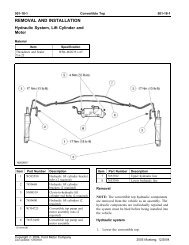
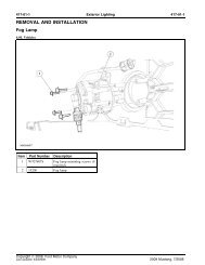
<strong>Ford</strong> <strong>Racing</strong> <strong>Laguna</strong> <strong>Gauge</strong> <strong>Pack</strong> <strong>Installation</strong> ManualThese instructions will guide you through the aftermarket installation of thesecomponents on your 2011 and newer Mustang vehicle.Step 1: Disconnect the negative vehicle battery terminal before beginning anywork on your vehicle.Step 2: Remove instrument cluster bezel. This part snaps out from the dash.Grab it at either end and carefully pull straight back to pop the bezel out of itsmoorings.WWW.FORDRACINGPARTSDIRECT.COMVl.OPg4of12
<strong>Ford</strong> <strong>Racing</strong> <strong>Laguna</strong> <strong>Gauge</strong> <strong>Pack</strong> <strong>Installation</strong> ManualStep 3: Prepare Instrument Panel (IP) for installation of gauge pod mountingbracket. Use the template on last page of these instructions to locate the 4 holesnecessa for connecti the mounti bracket to the IP.Note: A standard drill does not fit in the space between the dash and thewindshield. It is recommended that the installer use a small 90 degree drill or atool like a Dremel to make the required holes. Alternatively, a ~, 90 degree diegrinder with a 1 /8" collet adapter works well (pictured below). If you do notalready own these tools, Harbor Freight is a good source for inexpensive toolscapable of performing these tasks.WWW.FORDRACINGPARTSDIRECT.COMWhen cutting/drilling the IP, use a vacuum cleaner to suction from inside the IP toavoid accumulation of debris behind the dash/radio.Step 4: Loosely mount the gauge pod bracket to the IP dash pad with thesupplied fasteners, then use the bracket as a template to locate and mark thewire harness pass through hole. Remove the bracket and cut the hole for theVl.O Pg 5 of 12
<strong>Ford</strong> <strong>Racing</strong> <strong>Laguna</strong> <strong>Gauge</strong> <strong>Pack</strong> <strong>Installation</strong> Manualwire harness pass through. It is best to use a die-grinding bit to make the centerhole. Start with a~" hole made by a drill bit, then enlarge the hole with the diegrindingbit.Step 5: Install mounting bracket to dash as shown below using the 4 screwsprovided- do not over tighten .WWW.FORDRACINGPARTSDIRECT.COMVl.OPg6of12
<strong>Ford</strong> <strong>Racing</strong> <strong>Laguna</strong> <strong>Gauge</strong> <strong>Pack</strong> <strong>Installation</strong> ManualStep 6a: Pass gauge pod wire harness through IP dash pad and mount thegauge pod to the mounting bracket by sliding the clip on the back of the gaugepod into the socket of the mountin~ brac~et (refer t...,..o_.~_i_ct_u_re_b,~e-~~---'!t"'Step 6b: Install remaining two screws through front of gauge pod to secureinstallation of the to the mountin bracket.WWW.FORDRACINGPARTSDIRECT.COMVl.O Pg7of12 ;
<strong>Ford</strong> <strong>Racing</strong> <strong>Laguna</strong> <strong>Gauge</strong> <strong>Pack</strong> <strong>Installation</strong> ManualStep 7: Route the CM-6304WHRN-MA vehicle wire harness underneath theinstrument panel. Connect the vehicle wire harness connector to the gauge podconnector.WWW.FORDRACINGPARTSDIRECT.COMStep 8: The takeout for the oil pressure sender routes through the largegrommet in the driver's side foot well. Identify the service nub in this largegrommet just inboard of the OEM wiring harness. Remove a small portion of thisnub as required to permit pass through of the wire harness.CAUTION: Only remove enough of the service nub to permit a snug fit of thegrommet around the gauge pack wiring harness. Removing too much of theservice nub will allow gases and noise from the engine compartment to enter thepassenger compartment.Pass the 3 wires for the oil pressure sender through the service nub in thegrommet. The wires are delivered with a temporary covering of heat shrink tofacilitate routing through the grommet. Remove the heat shrink after routing thetakeout through the grommet. Verify that there are three wires in this takeoutlabeled 0-P-A, 0-P-B and 0-P-C.Vl.O Pg 8 of 12
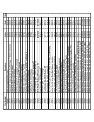
<strong>Ford</strong> <strong>Racing</strong> <strong>Laguna</strong> <strong>Gauge</strong> <strong>Pack</strong> <strong>Installation</strong> ManualStep 9: Install oil pressure sensor connector on gauge pack vehicle harness asfollows:1) Wire marked 0-P-A, insert into connector at cavity 1 .2) Wire marked 0-P-B, insert into connector at cavity 23) Wire marked 0-P-C, insert into connector at cavity 3Step 10: Remove OEM Oil Pressure sending unit and replace with CRJZ-90290-A Oil Pressure sending unit included with kit. Apply a thread sealingcompound or Teflon tape to the threads of the new oil pressure sender beforeinstalling.Step 11: Attach harness connector.WWW.FORDRACINGPARTSDIRECT.COMStep 12: Remove unused OEM oil pressure connector from the OEM harness.Stagger cut the two wires that go to this connector and individually apply heatshrink to each wire to seal and to prevent any future short circuit events.Step 13: The gauge pack requires communication with the vehicle's instrumentcluster in order to drive the oil pressure lamp in the cluster and receivebrightness/dimming commands from the driver. The wires listed below must bespliced to the instrument cluster wiring harness to accomplish this interface. Usethe butt splice terminals and heat shrink provided . Crimp the butt spliceterminals using a standard W' crimp tool. Soldering of the wires may beperformed instead of using the butt splice terminals if desired.C220-1: splice to cavity 1 Yellow I Red wire on instrument cluster connector.C220-3: splice to cavity 3 Blue I Brown wire on instrument cluster connector.Vl.O Pg 9 of 12
<strong>Ford</strong> <strong>Racing</strong> <strong>Laguna</strong> <strong>Gauge</strong> <strong>Pack</strong> <strong>Installation</strong> ManualC220-5: splice to cavity 5 Grey wire on instrument cluster connector.C220-12: splice to cavity 12 White wire on instrument cluster connector.C220-13: splice to cavity 13 White /Blue wire on instrument cluster connector.Refer to the diagram below for instrument cluster connector pinout information.Pin Ctrouit <strong>Gauge</strong> Circuit FunctionSBP26 2'0 FUSE - 26 OR CIRCLIH MEAKER(YE-RD)2 Not Use-d3 CB?36 22 FUSE- 36 OR ClRCU!T BREAKER(Bll-BNi4 RMG27 22 CTRL MOD.- IN'STRUMENT CWS1ER(VIH-BN)It SWITCH INFORMA.TDN / MESSi\GECENTER SELECT5 CMC2! 22 SWITG!-'1- OIL PRESSURE(GY)6 CMC29 22 SWITCH- INFCJf\MATION I MESSAGE(GN-Vr)CENTER SELECT7 CGA.15 2'0 SWITCH- IVD/TCS DfS.ABLE(YE-GY)8 GD116 18 GROUND - CROSS CAR BEAM 11 3RD(BK-V1)STUD9 Vt.ICso 22 COMPASS MOO.ll -(Bll-GYJ10 VMG31 22 COO PASS M00.11 +(GY-BUi11 Not Used12 VDBos 22 CONNECTOR- 00\GNOSTIC ll CANM"HIBUS HIGH SPEED LCNt13 VD~ 22 CONNECTOR - DiA.GNOSOC 11 CANlWH-BU)BUS HIGH SPEED HIGH14 Not Used1'5 VMC11 22 SENSOR- FUEL LEVEL (FU)lYE-vn16 RMC32 22 CTHL MOD. - SENSOR FUEL LEVEL{GN-BU}17 NC/1 Use-d18 VMC2S 22 SEI'\ISOR - FUEL LEVEL 2 (Fl.!)(GN-OG)19 RMG33 22 CTRLMOD.- SENSOR FUEL LEVEL2!WH-VT)20 Not Used21 Not Use-d2:2 VRT2S 22 TRA.NSCEIVER - PASSIVE ANTI THEFT(VT-GYJ(IMMOBIUZER)ll RX DATA (RX_I I:23 VRT24 22 TRANSCEIVER - PASSIVE ANTI THEFTfYE.OG)(IMMOBILIZER) u TX CNTRL24 Not Used25 VDI307 22 CONNECTOR- OIAGNOSTIC ll CAN(VT-OG~BUS MEDIUM SPEED LOW26 V:DB«i 22 CONNECTOR- EJlAGNOST!C ll CAN(GY-OG)BUS MEDIUM SPEED HIGHWWW.FORDRACINGPARTSDIRECT.COMIOualifie,riIIVl.O Pg 10 of 12
<strong>Ford</strong> <strong>Racing</strong> <strong>Laguna</strong> <strong>Gauge</strong> <strong>Pack</strong> <strong>Installation</strong> ManualStep 14:Step 15: Re-assemble vehicle and test.WWW.FORDRACINGPARTSDIRECT.COMVl.O Pg 11 of 12
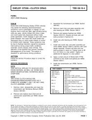
<strong>Ford</strong> <strong>Racing</strong> <strong>Laguna</strong> <strong>Gauge</strong> <strong>Pack</strong> <strong>Installation</strong> ManualAppendix A: <strong>Gauge</strong> Pod Mounting Bracket Templater I-~- +WWW.FORDRACINGPARTSDIRECT.COMlVl.OPg12of12