Supra July 151209 PDF.indd
Supra July 151209 PDF.indd
Supra July 151209 PDF.indd
- No tags were found...

Create successful ePaper yourself
Turn your PDF publications into a flip-book with our unique Google optimized e-Paper software.
SUPRAStainless SteelSingle WallChimney Systemfor CondensingAppliancesConfidence In Quality
INDIVIDUAL COMPONENTSLENGTHSAvailable in ‘nominal’ installed lengths asdetailed in the table belowInstalled Length (Std <strong>Supra</strong>)SizePart Number40101XX 40102XX 40103XX80mm-150mm988mm 458mm 193mm180mm-350mm969mm 459mm 204mmInstalled Length (<strong>Supra</strong> 1.0)Part NumberSize40201XX 40202XX 40203XX180mm-600mm975mm 459mm 204mmLengths (Std. <strong>Supra</strong>)Size988mm/969mm458mm/459mm193mm/204mmCode Number80mm 4010108 4010208 4010308100mm 4010110 4010210 4010310113mm 4010111 4010211 4010311130mm 4010113 4010213 4010313150mm 4010115 4010215 4010315180mm 4010118 4010218 4010318200mm 4010120 4010220 4010320250mm 4010125 4010225 4010325300mm 4010130 4010230 4010330350mm 4010135 4010235 4010335Lengths (<strong>Supra</strong> 1.0mm)Size988mm/969mm458mm/459mm193mm/204mmCode Number180mm 4020118 4020218 4020318200mm 4020120 4020220 4020320250mm 4020125 4020225 4020325300mm 4020130 4020230 4020330350mm 4020135 4020235 4020335400mm 4020140 4020240 4020340500mm 4020150 4020250 4020350600mm 4020160 4020260 402036075mm minimum to230mm maximuminstalled lengthAdjustable LengthDesigned to be used to make up arequired length between two components.It should be used with a standard lengthwhich MUST be ordered separately. Itcan also be inserted into the female end ofother components, but however applied,must engage a depth equivalent to at leasthalf the diameter of the <strong>Supra</strong> being used.The Adjustable Length for <strong>Supra</strong> 0.5mm isalso supplied with a special Locking Bandand Seal which must only be used forcondensing applications. Please note thatthe 1.0mm <strong>Supra</strong> product is NOT suppliedwith the special Locking Band and Sealand these MUST be ordered separatelyif required, see below. The AdjustableLength does not load bear. Alwayssupport the sections of <strong>Supra</strong> immediatelyabove with a Wall Support or SupportPlate. See Installation Instructions on page11 for further details.Specifi cation and Code NumbersThick 0.5mm <strong>Supra</strong> 1.0mm <strong>Supra</strong>Size80mm 4014408 -100mm 4014410 -113mm 4014411 -130mm 4014413 -150mm 4014415 -180mm 4014418 4024418200mm 4014420 4024420250mm 4014425 4024425300mm 4014430 4024430350mm 4014435 4024435400mm - 4024440500mm - 4024450600mm - 4024460Adjustable Locking Band andSeal (1.0mm <strong>Supra</strong>)Where 1mm <strong>Supra</strong> product is usedfor WET / CONDENSING applications,this item MUST be ordered for eachAdjustable Length.Locking BandsThis component must be used on everyjoint between components.Needs to be ordered separatelySizeCode Number80mm 4017008100mm 4017010113mm 4017011130mm 4017013150mm 4017015180mm 4027018200mm 4027020250mm 4027025300mm 4027030350mm 4027035400mm 4027040500mm 4027050600mm 4027060A (Installed length)BCSizeCode Number180mm 4007218200mm 4007220250mm 4007225300mm 4007230350mm 4007235400mm 4007240500mm 4007250600mm 4007260Inspection LengthDesigned to be installed within thesystem to allow access for inspectionand cleaning. The door closes on anelastomer seal to provide a water andpressure resistant joint and must onlybe used where the fl ue gas temperaturewill NOT exceed 200°C. For hightemperature applications both the innerand outer door seal must be removedprior to installation.SizeCode No.0.5 mm<strong>Supra</strong>Code No.1.0 mm<strong>Supra</strong>A B C80mm 4011008 - 195 70 100100mm 4011010 - 195 70 110113mm 4011011 - 283 113 135130mm 4011013 - 283 113 160150mm 4011015 - 283 113 170180mm 4011018 4021018 289 127 170200mm 4011020 4021020 289 127 170250mm 4011025 4021025 289 127 170300mm 4011030 4021030 289 127 170350mm 4011035 4021035 289 127 170400mm - 4021040 289 127 170500mm - 4021050 289 127 170600mm - 4021060 289 127 1704
AATEES AND ELBOWSBBFGC90°DC90° TeeUsed to provide a 90° connection in asystem run or can be used as an access/ inspection point when used with aLocking PlugSizeCode No.0.5 mm<strong>Supra</strong>Code No.1.0 mm<strong>Supra</strong>A B C80mm 4010508 - 283 110 90100mm 4010510 - 283 110 90113mm 4010511 - 283 112 95130mm 4010513 - 283 112 100150mm 4010515 - 283 112 125180mm 4010518 4020518 289 126 131200mm 4010520 4020520 459 211 131250mm 4010525 4020525 459 211 217300mm 4010530 4020530 459 211 217350mm 4011035 4020535 459 211 217400mm - 4020540 969 466 303500mm - 4020550 969 466 303600mm - 4020560 969 466 477135° Tee and 45° ElbowconfigurationUsed to provide a 90° connection in asystem run or can be used as an access/ inspection point when used with aLocking PlugSize D E F GE 80mm - - - -100mm - - - -113mm 283 310 200 242130mm 308 319 218 264150mm 336 352 238 288180mm 376 417 266 343200mm 404 427 286 367250mm 476 453 337 429300mm 546 900 386 488350mm 616 750 436 548400mm 697 783 493 632500mm 839 832 593 753600mm 979 881 692 872135° Equal TeeUsed to provide a 45° connection in asystem run or as the entry point to achimney. Can be used as an access/ inspection point when used with aLocking Plug or as a drain when fi ttedwith a Condensate Collector.SizeCode No.0.5 mm<strong>Supra</strong>Code No.1.0 mm<strong>Supra</strong>A B C80mm 4012280 - - - -100mm 4012210 - - - -113mm 4012211 - 283 173 177130mm 4012213 - 283 182 198150mm 4012215 - 327 213 222180mm 4012218 4022218 459 308 256200mm 4012220 4022220 459 318 280250mm 4012225 4022225 459 343 341300mm 4012230 4022230 969 455 401350mm 4012235 4022235 969 655 461400mm - 4022240 969 679 521500mm - 4022250 969 730 642600mm - 4022260 969 780 762ABAABC95°95° Equal TeeThe tee is provided with a 5° connectionon the branch to allow for condensatedrainage. Can be used at the base of avertical stack or to facilitate a 5° inclineSizeCode No.0.5 mm<strong>Supra</strong>Code No.1.0 mm<strong>Supra</strong>A B C80mm 4011908 - 283 107 90100mm 4011910 - 283 108 90113mm 4011911 - 283 110 90130mm 4011913 - 283 109 100150mm 4011915 - 327 108 125180mm 4011918 4021918 289 126 131200mm 4011920 4021920 459 211 131250mm 4011925 4021925 459 211 217300mm 4011930 4021930 459 211 217350mm 4011935 4021935 459 211 217400mm - 4021940 969 466 303500mm - 4021950 969 466 303600mm - 4021960 969 466 477Locking PlugUsed to close off the branch or base of atee or the end of a header/manifold. Heldin position with a Locking band.Size Code Number A80mm 4014908 82100mm 4014910 82113mm 4014911 82130mm 4014913 82150mm 4014915 82180mm 4024918 70200mm 4024920 70250mm 4024925 70300mm 4024930 70350mm 4024935 70400mm 4024940 70500mm 4024950 70600mm 4024960 70Condensate CollectorUsed at the bottom of a vertical run,usually under a Tee, to facilitate drainageof condensates from the system. Thecomponent includes a stainless steelBSP connection to allow drainagepipework to be connected by others.Size Code Number A B80mm 4014308 82 1”100mm 4014310 82 1”113mm 4014311 82 1”130mm 4014313 82 1”150mm 4014315 82 1”180mm 4024318 70 1”200mm 4024320 70 1”250mm 4024325 70 1”300mm 4024330 70 1”350mm 4024335 70 1”400mm 4024340 70 2”500mm 4024350 70 2”600mm 4024360 70 2”5
A100-350: 1” BSP400-600: 2” BSPA100-350: 1” BSP400-600: 2” BSPHorizontal Duct DrainUsed as a drainage point on the endof an inclined manifold or inclined run.Incorporates an internal condensate damand BSP stainless steel connection forcondensate drainage. Also supplied withfi xed end cap. Note: The Cap cannotbe removed.With CapSize0.5mm <strong>Supra</strong> 1mm <strong>Supra</strong>Code No. A Code No. A100mm 4011810 182 - -113mm 4011811 182 - -130mm 4011813 182 - -150mm 4011815 182 - -180mm 4011818 182 4021818 200200mm 4011820 182 4021820 200250mm 4011825 182 4021825 200300mm 4011830 193 4021830 200350mm 4011835 193 4021835 200400mm - - 4021840 200500mm - - 4021850 200600mm - - 4021860 200Without CapSize0.5mm <strong>Supra</strong> 1mm <strong>Supra</strong>Code No. A Code No. A100mm 4010810 200 - -113mm 4010811 200 - -130mm 4010813 200 - -150mm 4010815 200 - -180mm 4010818 200 4020818 200200mm 4010820 200 4020820 200250mm 4010825 200 4020825 200300mm 4010830 200 4020830 200350mm 4010835 200 4020835 200400mm - - 4020840 200500mm - - 4020850 200600mm - - 4020860 20040°45°AABB40° ElbowUsed to provide a 40° change ofdirection from the vertical.Size0.5mm <strong>Supra</strong> 1mm <strong>Supra</strong>Code No. A B Code No. A B80mm 4019808 84 172 - - -100mm 4019810 91 191 - - -113mm 4019811 67 120 - - -130mm 4019813 69 125 - - -150mm 4019815 71 130 - - -180mm 4019818 75 162 4029818 70 149200mm 4019820 76 167 4029820 72 155250mm 4019825 83 185 4029825 78 172300mm 4019830 89 201 4029830 84 188350mm 4019835 94 217 4029835 90 204400mm - - - 4029840 113274500mm - - - 4029850 127311600mm - - - 4029860 13934645° ElbowUsed to provide a 45° change ofdirection from the vertical.Size0.5mm <strong>Supra</strong> 1mm <strong>Supra</strong>Code No. A B Code No. A B80mm 4014308 92 164 - - -100mm 4014310 100 183 - - -113mm 4014311 75 117 - - -130mm 4014313 78 124 - - -150mm 4014315 81 131 - - -180mm 4014318 85 162 4022318 80 150200mm 4014320 88 169 4022320 83 157250mm 4014325 95 187 4022325 91 176300mm 4014330 103 205 4022330 98 193350mm 4014335 110 222 4022335 105210400mm - - - 4022340 124263500mm - - - 4022350 139299600mm - - - 4022360 15333315°30°AABB15° ElbowUsed to provide a 15° change ofdirection from the vertical.Size0.5mm <strong>Supra</strong> 1mm <strong>Supra</strong>Code No. A B Code No. A B80mm 4012508 26 141 - - -100mm 4012510 27 148 - - -113mm 4012511 23 113 - - -130mm 4012513 24 117 - - -150mm 4012515 24 119 - - -180mm 4012518 25 144 4022518 23 130200mm 4012520 25 146 4022520 23 132250mm 4012525 26 152 4022525 24 138300mm 4012530 27 159 4022530 25 146350mm 4012535 27 165 4022535 26 152400mm - - - 4022540 31 197500mm - - - 4022550 33 211600mm - - - 4022560 34 22430° ElbowUsed to provide a 30° change ofdirection from the vertical.Size0.5mm <strong>Supra</strong> 1mm <strong>Supra</strong>Code No. A B Code No. A B80mm 4012408 58 157 - - -100mm 4012410 61 168 - - -113mm 4012411 49 119 - - -130mm 4012413 50 123 - - -150mm 4012415 52 128 - - -180mm 4012418 54 157 4022418 50 144200mm 4012420 55 162 4022420 52 149250mm 4012425 58 173 4022425 55 160300mm 4012430 62 187 4022430 58 173350mm 4012435 65 200 4022435 62 187400mm - - - 4022440 74 237500mm - - - 4022450 80 262600mm - - - 4022460 87 286AABB85° ElbowUsed to provide a 85° change ofdirection from the vertical. Also for useon condensing systems to allow a 5°incline to aid drainage of condensateback through the system.Size0.5mm <strong>Supra</strong> 1mm <strong>Supra</strong>Code No. A B Code No. A B80mm 4012708 145 100 - - -100mm 4012710 153 109 - - -113mm 4012711 156 113 - - -130mm 4012713 163 114 - - -150mm 4012715 172 124 - - -180mm 4012718 186 160 4022718 186160200mm 4012720 196 170 4022720 196170250mm 4012725 218 195 4022725 212195300mm 4012730 241 220 4022730 235219350mm 4012735 264 245 4022735 258244400mm - - - 4022740 343338500mm - - - 4022750 388386600mm - - - 4022760 43443790° ElbowUsed to provide a 90° change ofdirection.Size0.5mm <strong>Supra</strong> 1mm <strong>Supra</strong>Code No. A B Code No. A B80mm 4012808 150 90 - - -100mm 4012810 160 100 - - -113mm 4012811 162 105 - - -130mm 4012813 171 107 4022713 171128150mm 4012815 180 116 4022715 180137180mm 4012818 196 153 4022718 196153200mm 4012820 205 162 4022720 205162250mm 4012825 231 188 4022725 225188300mm 4012830 255 212 4022730 249212350mm 4012835 280 237 4022735 274237400mm - - - 4022740 357320500mm - - - 4022750 405368600mm - - - 4022760 4524156
130mm130mmAADAPTORSFlue SizeFlue SizePositioned as an in-linecondensate applianceadaptorBAAAAppliance AdaptorUsed to connect the <strong>Supra</strong> product tothe appliance. The interface betweenthe Adaptor and the appliance outletshould be sealed with silicon sealantwhen used on condensing appliances orfi re cement when used on solid fuel.Size0.5mm <strong>Supra</strong> 1mm <strong>Supra</strong>Code No. A B Code No. A B80mm 4019308 63 205 - - -100mm 4019310 63 205 - - -113mm 4019311 63 205 - - -130mm 4019313 63 205 - - -150mm 4019315 63 205 - - -180mm 4019318 42 197 4028318 42 197200mm 4019320 42 197 4028320 42 197250mm 4019325 42 197 4028325 42 197300mm 4019330 42 197 4028330 42 197350mm 4019335 42 197 4028335 42 197400mm - - - 4028340 42 197500mm - - - 4028350 42 197600mm - - - 4028360 42 197Appliance Adaptor withCondense TrapUsed to connect the <strong>Supra</strong> product tothe appliance and drain condensatefrom the system where used on higheffi ciency and condensing appliances.The interface between the Adaptor andthe appliance outlet should be sealedwith silicon sealant. The design helpsdivert condensates through an 18mmOD stainless steel tube to which drainhose can be connected, prior to enteringthe appliance.Size0.5mm <strong>Supra</strong> 1mm <strong>Supra</strong>Code No. A Code No. A80mm 4011408 130 -100mm 4011410 130 - -113mm 4011411 130 - -130mm 4011413 130 - -150mm 4011415 130 - -180mm 4011418 130 4021418 130200mm 4011420 130 4021420 130250mm 4011425 130 4021425 130300mm 4011430 130 4021430 130350mm 4011435 130 4021435 130400mm - - 4021440 130500mm - - 4021450 130600mm - - 4021460 130<strong>Supra</strong> to Nova adaptorDesigned to facilitate connection fromthe <strong>Supra</strong> to Nova chimney system.Size A Code Number100mm 63 4579604N130mm 63 4579605N150mm 63 4579606N180mm 42 4579607N200mm 42 4579608N250mm 42 4579610N300mm 42 4579612N350mm 42 4579614NNova to <strong>Supra</strong> adaptorDesigned to facilitate connection fromthe Nova to <strong>Supra</strong> chimney system.Size A Code Number100mm 63 4579704N130mm 63 4579705N150mm 63 4579706N180mm 42 4579707N200mm 42 4579708N250mm 42 4579710N300mm 42 4579712N350mm 42 4579714N80mm204mmA (ID)100mmSUPPORT COMPONENTSABAdaptor to FlexUsed to connect the <strong>Supra</strong> product to afl exible fl ue/chimney liner.SizeDimensionsA BCode Number80mm 88 63 4015908100mm 108 63 4015910130mm 138 63 4015913150mm 158 63 4015915180mm 188 63 4025918200mm 208 63 4025920Support LengthThe Support Length can serve twoapplications, fi rstly allowing a <strong>Supra</strong>liner to be lowered down a chimney andsecondly as a Support Length whenused with the Support Plate (less thecollar).In all cases, ALL the lugs on the SupportLength MUST be used when loweringthe product. The maximum length ofproduct that can be supported by thecomponent is 30 metres.Specifi cation and Code NumbersThick 0.5mm <strong>Supra</strong> 1.0mm <strong>Supra</strong>Size80mm 4010408 -100mm 4010410 -113mm 4010411 -130mm 4010413 -150mm 4010415 -180mm 4010418 4020418200mm 4010420 4020420250mm 4010425 4020425300mm 4010430 4020430350mm 4010435 4020435400mm - 4020440500mm - 4020450600mm - 4020460Bracing BracketUsed to provide lateral stability back tosupport structure. This component mustonly be used with rigid stays and can befi tted anywhere on the pipe other thanbetween the swages. Structural calculationsmust be made for each application.Rigid stays must be connected to thethree fi xing points of this three part component.The hole diameters for the M6nuts and bolts are 7mm. Constructedfrom stainless steel.Size A Code Number60mm 62 406920680mm 82 4069208100mm 102 4069210113mm 115 4069211130mm 132 4069213150mm 152 4069215180mm 182 4069218200mm 202 4069220250mm 252 4069225300mm 302 4069230350mm 352 4069235400mm 402 4069240500mm 502 4069250600mm 602 40692607
20mmASupport PlateConsists of a stainless steel plate witha three part support collar. The collarrests on the plate and is located underthe bead/swage at a joint betweencomponents. The three fi xing pointsof the collar rest on the plate, the holein which being large enough to permitthe passage of the swages of the <strong>Supra</strong>construction.The plate must be adequately supportedand secured to an adjacent structure.This component can also be used inconjunction with a Support Length, butthe collar would be discarded for thisapplication.This component or a Wall Support MUSTALWAYS be used above an AdjustableLength where applied in a verticalapplication, or where the AdjustableLength would be otherwise liable toload. The maximum length which canbe supported by this component is 30metres.Size A Code Number80mm 147 4051108100mm 260 4051110113mm 260 4051111130mm 275 4051113150mm 300 4051115180mm 325 4051118200mm 350 4051120250mm 400 4051125300mm 450 4051130350mm 500 4051135400mm 550 4051140500mm 650 4051150600mm 750 4051160ALocation BandThis component consists of a strapwhich must be secured underneath ajoint. It has four equally located stainlesssteel “spokes” designed to centrallylocate and brace the system wherelowered into an existing chimney orshaft, and should be used at intervals notexceeding 3 metres. Constructed fromstainless steel.Bespoke Location Bands tofacilitate non-standard shafts can bemanufactured to order. Please refer toSFL Technical Department with yourrequirement.Size A Code Number80mm 350 4017108100mm 375 4017110113mm 375 4017111130mm 390 4017113150mm 410 4017115180mm 540 4017118200mm 560 4017120250mm 610 4017125300mm 660 4017130350mm 850 4017135400mm 900 4017140500mm 1000 4017150600mm 1100 4017160CABA80 - 100mm IDAWall Support BracketThis component is basically a Wall Bandwith additional side support struts whichcan be located below or above theband. In either case the band is locatedunder the bead/swage at a joint betweenthe components. The maximumlength which can be supported by thiscomponent is 30 metres. Only availablefor diameters of 130mm and above.Constructed from stainless steel.SizeDimensions CodeA B C Number130mm 178 115 92 4051213150mm 190 122 112 4051215180mm 207 137 142 4051218200mm 219 147 162 4051220250mm 248 172 212 4051225300mm 286 198 266 4051230350mm 316 223 316 4051235400mm 345 248 366 4051240Wall BandTo be used at intervals not exceeding 2.5metres to provide lateral stability for bothvertical and horizontal applications withinthe system. Manufactured from stainlesssteel and suitable for both internal andexternal applications.Size A Code Number80mm 63.5 3115084100mm 83.5 3115104113mm 75 3115114130mm 92 3115134150mm 112 3115154180mm 142 3115185200mm 162 3115205250mm 212 3115255300mm 266 3115305350mm 316 3115355400mm 366 3115405500mm 467 3115505600mm 567 3115605FLASHINGS AND WEATHERINGCCABABFlat FlashingSizeDimensions CodeA B C Number100mm 110 200 419 70000001113mm 123 213 419 70000004130mm 140 230 419 70000005150mm 160 250 455 70000006180mm 190 280 495 70000007200mm 210 300 495 70000009250mm 260 350 610 70000011300mm 310 400 610 70000012350mm 360 450 660 70000013400mm 410 500 762 70000014500mm 510 600 914 70000016600mm 610 700 1015 700000185° - 30° Angled FlashingSizeDimensions CodeA B C Number100mm 110 190 394 70053001113mm 123 204 419 70053004130mm 140 225 419 70053005150mm 160 247 445 70053006180mm 190 281 495 70053007200mm 210 304 508 70053009250mm 260 361 578 70053011300mm 310 419 610 70053012350mm 360 476 678 70053013400mm 410 533 762 70053014500mm 510 710 1010 70053016600mm 610 824 1124 700530188
CCAABAB32° - 45° Angled FlashingSizeDimensions CodeA B C Number100mm 110 261 480 70324501113mm 123 279 495 70324504130mm 140 303 508 70324505150mm 160 332 559 70324506180mm 190 375 578 70324507200mm 210 403 610 70324509250mm 260 475 678 70324511300mm 310 546 737 70324512350mm 360 617 820 70324513400mm 410 689 889 70324514500mm 510 812 1124 70324516600mm 610 963 1300 70324518Storm CollarSizeDimensions CodeA B C Number100mm 102 201 70 70123401113mm 115 214 70 70123404130mm 132 231 70 70123405150mm 152 251 70 70123406180mm 182 281 70 70123407200mm 202 301 70 70123409250mm 252 330 70 70123411300mm 302 351 70 70123412350mm 352 401 70 70123413400mm 402 451 70 70123414500mm 502 673 150 70123416600mm 602 773 150 70123418TERMINALS AND TERMINATIONABTapered Top Stub and MeshThis terminal should be used with gascondensing appliances as it offers leastresistance to fl ow and help minimise theeffects of pluming.SizeDimensionsA BCode Number80mm 70 291 4016008100mm 90 291 4016010113mm 100 291 4016011130mm 120 291 4016013150mm 140 291 4016015180mm 160 228 4016018200mm 180 228 4016020250mm 200 228 4016025300mm 250 228 4016030350mm 300 228 4016035400mm 350 276 4026040500mm 400 276 4026050600mm 500 276 4026060Tapered Top StubThis terminal offers least resistance tothe evacuation of fl ue gases and shouldonly be used in accordance with theregulations.SizeDimensionsA BCode Number80mm 70 291 4015808100mm 90 291 4015810113mm 100 291 4015811130mm 120 291 4015813150mm 140 291 4015815B 180mm 160 228 4015818200mm 180 228 4015820250mm 200 228 4015825300mm 250 228 4015830350mm 300 228 4015835400mm 350 276 4025840500mm 400 276 4025850600mm 500 276 4025860BACED43mmRain CapThis is a basic terminal that offers a degreeof protection against rain ingressSizeCode Number80mm 4055208100mm 4055210113mm 4055211130mm 4055213150mm 4055215180mm 4055218200mm 4055220250mm 4055225300mm 4055230350mm 4055235400mm 4055240500mm 4055250600mm 4055260Gas TerminalA terminal designed for use where <strong>Supra</strong>serves conventional gas fi red equipment.Sizes 80mm to 150mm.Incorporates a bird screen/mesh.SizeCode Number80mm 4006108100mm 4006110113mm 4006111130mm 4006113150mm 4006115180mm 4006118200mm 4006120250mm 4006125300mm 4006130350mm 4006135400mm 4006140500mm 4006150600mm 4006160<strong>Supra</strong> Terminal KitThe <strong>Supra</strong> Terminal Kit is designed foruse where <strong>Supra</strong> is located within achimney or shaft. It consists of a plateand a 100mm upstand (drum) which istraditionally weathered to the top of theshaft. The “drum” is signifi cantly greaterin diameter than the <strong>Supra</strong> product, toprovide passive ventilation to the shaft/ chimney. Four integral stainless steelstraps centrally locate the <strong>Supra</strong> whenthe unit is lowered over the product.The projecting length of <strong>Supra</strong> abovethe “drum” is then rainproofed using theStorm Collar provided as part of the kit.100mmSizeDimensionsCodeA B C D E Number80mm 82 280 167 298 348 4005408100mm 102 300 187 298 348 4005410113mm 115 310 200 298 348 4005411130mm 132 330 214 472 522 4005413150mm 152 350 234 472 522 4005415180mm 182 380 264 472 522 4005418200mm 202 400 284 472 522 4005420250mm 252 450 334 472 522 4005425300mm 302 500 384 646 696 4005430350mm 352 550 434 646 696 4005435400mm 402 600 484 646 696 4005440500mm 502 700 584 750 800 4005450600mm 602 800 684 850 900 40054609
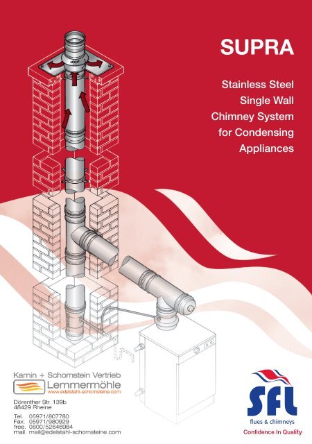
ELBOW OFFSET DIMENSIONSCABA15° OffsetSizeDimensionsA B C80mm 43 281 37100mm 47 296 39113mm 36 226 30130mm 38 234 31150mm 39 238 32180mm 52 288 39200mm 53 291 39250mm 56 303 40300mm 60 319 42350mm 63 331 44400mm 82 393 52500mm 89 426 56600mm 96 448 5930° OffsetSizeDimensionsA B C80mm 57 313 86100mm 63 335 92113mm 34 237 66130mm 36 245 71150mm 39 256 71180mm 64 313 87200mm 67 324 90250mm 73 347 95300mm 80 373 102350mm 87 399 109400mm 110 477 128500mm 123 530 142600mm 136 575 15445° OffsetSizeDimensionsA B C80mm 72 328 143100mm 83 365 158113mm 42 234 105130mm 46 248 110150mm 50 261 116180mm 77 324 141200mm 81 337 145250mm 92 375 161300mm 102 409 175350mm 112 443 189400mm 139 537 222500mm 160 608 254600mm 180 677 281TYPICAL CONDENSING APPLICATIONFig. 3Top Stub with Mesh (4016020)204mm Length (4010320)Storm Collar (70123409)Flat Flashing (70000009)Wall Band (3115205)459mm Length (4010220)969mm Length (4010120)459mm Length (4010220)200ID X 150ID 95° Red. TeeLocking plug with drain (4011820)Wall Support Bracket (4051220)Connection to drain/gully458mm Length (4010215)95° Tee (4011920)Condense Collector (4014320)Adjustable Length (4010220)10
INSTALLATION INSTRUCTIONSMandatory RequirementsIn all instances the requirements of the Building Regulations mustbe complied with and the appropriate references are: DocumentJ of the DOE Building Regulations, Section F of the BuildingStandards (Scotland), Section L of the Building Regulations(Northern Ireland). Reference should also be made to the relevantBritish and European Standards governing the installation of fl ueand chimney products for the associated fuel and appliance typesas detailed:Solid Fuel and Oil Fired Applications: BS EN15287-1:2007Domestic Gas Installations: BS5440: Part 1: 2008Note: In the UK, connection to an appliance which is notconnected to the fuel supply, may be carried out by a competentperson. However, connection to an appliance that is connected tothe fuel supply must be carried out by an approved and registeredHeating Engineer, e.g. Gas Safe, HETAS (Solid Fuel) or OFTEC (Oil).General<strong>Supra</strong> must be applied such that the system complies with local/ national Building Regulations and applicable standards. Whereused on condensing appliances, the range of components willpermit deliberate drainage of condensate, either back to thecondensate removal components within the <strong>Supra</strong> System range,or through the heating appliance. No part of the fl ue systemshould be constructed to form an angle greater than 45˚ fromthe vertical. Although components are included that will permithorizontal applications, they should only be used for connectionto the appliance. Where the system is being used for a condensingapplication, it is required that sloping connections run at an angleof 5˚ from the horizontal, using the Tees, Elbows and fi ttingsdesigned for that purpose.If the system is to be used within an existing chimney or purposedesigned shaft, the range of support components will allow suchconfi gurations and can also be used to provide an independentand fully supported system both inside an outside a building.Where <strong>Supra</strong> is installed in exposed applications or where theexternal run is greater than 3.0 metres, SFL would recommend thatthe Nova SM product is used. Nova SM is a twin wall insulatedstainless steel system offering a high degree protection againstfreezing. Adaptors are available to allow conversion between thetwo products (See Page 7).JointingThe <strong>Supra</strong> system is jointed by pushing the male end into thefemale end of the proceeding component, and then applying aLocking Band. The Locking Band must be installed so that thetoggle is only closed from left to right. See Fig. 4.Ensure that both ends of the connecting joint are clean and free ofdirt / grit.Fig. 5 Standard Joint detailAdjustable LengthThe Adjustable Length consists of a section of SUPRA, the lowernon-beaded end of which is designed preferably to be located intoa standard length. It can also be inserted into the female end ofother components, but however applied, must engage to a depthequivalent to at least half of the diameter of the SUPRA being used.Where pressure and moisture resistance are required a specialLocking Band & Seal is required to make the joint.On standard <strong>Supra</strong>, the Adjustable Length is supplied completewith a special Locking Band & Seal. For <strong>Supra</strong> 1.0mm, thespecial Locking Band & Seal MUST be ordered separately.Fig. 6Jointdetailand sealprofi leLockingBandSealGas DirectionMale endFemalesocketLock Band detail for the Adjustable Lengthfor Condensing ApplicationsThe Lock Band isprofi led such thatwhen used with theAdjustable Length,the toggle must snapto the right, NOT tothe leftGasDirectionFig. 4Note that the Locking Band hasa profi le which will only correctlylocate one way round the joint.For that reason, it MUST belocated so that the toggle is onlyclosed from left to rightSprung toggle illustratedLock Bands fi tted withthis type of toggle shouldbe adjusted so that whenthe rod end is engaged inthe strike, the lever pin isbetween 5° and 10° pastthe centre lineAdjustable Lever togglerod endLever pinThe <strong>Supra</strong> 0.5mm product is supplied complete with factorybonded Elastomer Seals.For 1mm <strong>Supra</strong>, depending on the application, the joint can bemade pressure and moisture resistant using an Elastomer Sealwhich must be ordered separately. The Elastomer Seal should belocated and ideally bonded as shown in Fig. 5Note that the lips of the seal must point in one direction as shown.Because the seal is designed to provide a secure grip to the maleend of the component, SFL Seal Lubricating gel should be used tofacilitation ease of installation and to prevent potential damage ofthe seal during installation.5° - 10°Fig. 6 illustrates the joint detail. Locate the seal over the socketedfemale end of the length or component female end before insertingthe male end, and then pull the seal up so that the angled notchon its inside locates over the turned end of the female socket asshown. To facilitate easier assembly, apply SFL Joint Lubricantto the seal prior to installation. The Lock Band has two designsof toggle, either spring or adjustable. If using the band with theadjustable toggle, it should be tensioned as shown in Fig. 6 Notethat whichever type is applied, the profi le of the Lock Band issuch that it must only be applied one way round. If it is locatedincorrectly, the joint will be both insecure and inadequately sealed.11
INCREASERS / REDUCERSBAReducersReducers are used to reduce thediameter of the preceeding system byone diameter, e.g. 150ID to 130ID.FlueSizeA(mm)B(mm)Code(0.5mm)Code(1mm)BAIncreasersIncreasers are used to increase thediameter of the preceeding system byone diameter, e.g. 130ID to 150ID.FlueSizeA(mm)B(mm)Code(0.5mm)Code(1mm)Flue Size100mm 80 150 4012610 -113mm 80 150 4012911 -Flue Size80mm 100 150 4013008 -80mm 113 150 4012908 -113mm 100 120 4012611 -100mm 113 120 4013010 -130mm 113 120 4012613 -113mm 130 120 4013011 -150mm 130 120 4012615 -130mm 150 120 4013013 -180mm 150 120 4012618 4022618150mm 180 150 4013015 -200mm 180 120 4012620 4022620180mm 200 120 4013018 4023018250mm 200 165 4012625 4022625200mm 250 165 4013020 4023020300mm 250 165 4012630 4022630250mm 300 165 4013025 4023025350mm 300 165 4012635 4022635300mm 350 165 4013030 4023030350mm 400 165 4013035 4023035Note: Bespoke Reducers andIncreasers can be manufactured toorder, please send a dimensioneddrawing detailing your requirementsto SFL Technical Dept., who willevaluate your requirements.13